Part Number: TMS570LS0714
Other Parts Discussed in Thread: HALCOGEN, SN65HVD73
Dear TI Team
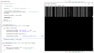
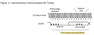
I am using the TMS570LS0714 in the PZ package. Currently I am trying to setup an SCI implementation using PIN 94 (LIN RX).
PIN 94 is connected with the RX singal of my external sensor.
My problem is that the sciNotification(sciBASE_t *sci, uint32 flags) function is not triggered by the RX interrupt (which is my intension)
Could you please have a look on my CCS code and Hal Gen settings?
Do you have an idea why sciNotification is not triggered?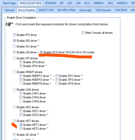
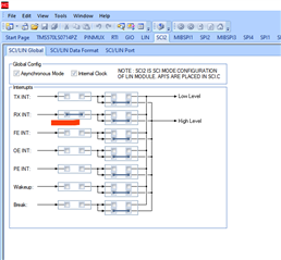
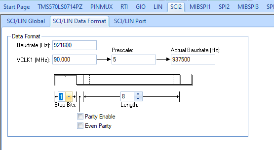
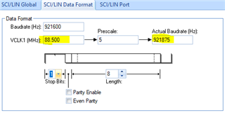
The settings in HAL GEN -> SCI2 -> SCI/LIN Global: was tested with RX int connected with High Level (as shown above) and tested with RX int NOT connected with High Level) both without success.
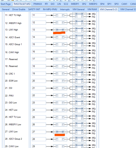
Also the settings in HAL GEN -> COM Ch. 0-31 was tested LIN1 High + LIN1 Low connected to IRQ and was tested with only LIN1 High conected to IRQ, both combinations without success./* USER CODE BEGIN (1) */
#include "sci.h"
#include "het.h"
#include "gio.h"
#include "system.h"
#include <stdio.h>
/* USER CODE END */
/* USER CODE BEGIN (2) */
uint8 sci_cmd;
/* USER CODE END */
int main(void)
{
/* USER CODE BEGIN (3) */
/* Initialize HET driver */
hetInit();
/* Initialize GIO driver */
gioInit();
gioSetBit(hetPORT1, 0, 1);
/* Initialize SCI and enable ISR */
sciInit();
sciReceive(scilinREG, 1, &sci_cmd);//sciReceive(sciREG, 1, &sci_cmd);
/* Enable Interrupt Processing */
//_enable_interrupt_();
_enable_IRQ ();
while(1)
{
}
/* USER CODE END */
return 0;
}
/* USER CODE BEGIN (4) */
void sciNotification(sciBASE_t *sci, uint32 flags)
{
printf("Test\r");
}
/* USER CODE END */
gioSetBit(hetPORT1, 0, 1) is set to activate the sensor
Thank you in advance!