
- Ask a related questionWhat is a related question?A related question is a question created from another question. When the related question is created, it will be automatically linked to the original question.
Dear team:
One of my clients conducted the following experiments:
Method 1: Use CLB to generate a pulse signal PULSE and direction signal DIR. The signal is output through GPIO and then connected to the QEP A/B pin to be able to count normally.
Method 2: The QEP configuration remains unchanged in Method 1, except that when QDIR and QCLK are internally connected, QEP cannot be counted (QPOSCNT is always zero). The contact signal between CLB and QEP is as follows:
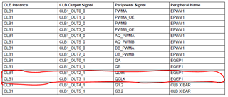
QDIR is the same as the DIR waveform in Method 1; QCLK is the pulse at the moment of the falling edge of the PULSE signal in Method 1, with a width of 10ns. The realization is through the new configuration statement: Clb1LogicCtrlRegs.CLB_OUT_EN = 3<<10; In this way, QEP cannot realize counting (QPOSCNT is always zero)
Please help analyze what caused the method 2 to not count?
Best regards


