This thread has been locked.

If you have a related question, please click the "Ask a related question" button in the top right corner. The newly created question will be automatically linked to this question.

LAUNCHXL-F28379D: Biss-c encoder reading issues

Part Number: LAUNCHXL-F28379D
Other Parts Discussed in Thread: CONTROLSUITE, TMS320F28379D

Hello all,

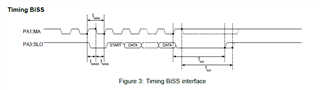
I am trying to read data from MU150 19-bit absolute encoder [link] connected to Ic-Haus evaluation board [link]. The master clk (MA) and server data (SLO) signal (non-differential) pins from the evaluation board are connected to launchpad as per the following figure from Biss-c position manager library document (sprui37). 


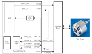
Following the above diagram, I made these connections within launchpad and to the evaluation board:
1. gpio-6 (pin J8:80) to MA clk on evaluation board
2. gpio-7 (pin J8:79) to gpio-26 (pin J6:53)
3. gpio-24 (pin J4:34) to SLO pin on evaluation board
4. gpio-25 (pin J6:51) is not connected
5. gpio-27 (pin J6:52) to GND (J6:60) of launch pad 
6. I did not configure and connect the PWR CTL pin to the encoder as the encoder evaluation board is powered independently. 

Now, on the software side, 

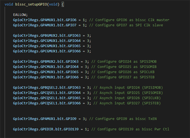
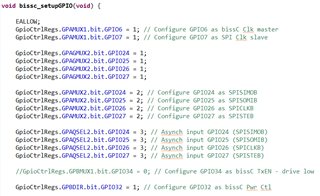
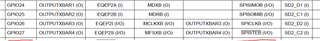
1. Used library from "<install_dir>\controlSUITE\libs\app_libs\position_manager\v01_02_00_00\bissc\examples". Includes screenshot below:

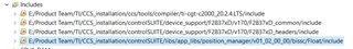
2. Changed position and crc bits to 19 and 6 respectively in "biss.h". 
3. Following some forum answers, added "F28x_Project.h" into "biss.h" and "volatile" to BISSC_DATA_STRUCT. 
4. CRC polynomials as per the encoder data sheet are 0x43 and 0x13 for SCD and CD. I tried those and also 0x03 and 0x03 (following one of the forum threads).
5. Created target configuration for F28379D with no compiler optimizations, the project builds with the following warnings:

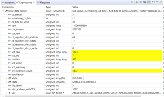
6. Now, when I debug with the launchpad and encoder board connected, the program stops at 'while (bissc_data_struct.dataReady != 1) {}' line. 
7. At this point, if I disconnect either of the two MA clk and SLO lines to the encoder evaluation board, the values are read but with incorrect CRCs. Of course, the values doesn't seem to increase/decrease as I rotate the encoder. A screenshot of the watch window is given below: 

Could anyone help me in troubleshooting the issue(s) I mentioned in points 5,6 and 7 above? Thank you in advance.  

  • connected to Ic-Haus evaluation board [link].

    Hello, Vikranth

    I'm not familiar with this board.   The example we provide is meant to connect through a https://www.ti.com/tool/BOOSTXL-POSMGR daughter card on the LaunchPad.  This daughter card includes the required transceivers for the communications physical layer.   I don't know if the evaluation board you are using takes care of this.. 

    The suggestion I have is to monitor the signals with a scope and make sure they are the right voltage levels at the right locations and that the BiSS frame looks correct.  

    Regards

    Lori

  • Hi Lori, thanks for your inputs. Just want to clarify two points.

    1. The board I am using just provides interface to clock and data lines on the encoder chip according to this figure: 

    2. I am connecting these lines directly to launchpad (following the first figure in previous question) without going through the daughter card. Could you please let me know if the example and biss library works the same without the daughter card and with non-differential clock and data signals ? 

    Thank you.

  • Vikranth,

    If I understand you have the following setup:

    encoder <---> iCHaus board <----> C2000

    The I/O pins on the C2000 are 3.3V.  Does the iCHaus board have transceivers to raise the voltage to the value required by the encoder?

    Regards

    Lori

  • Lori,

    Does the iCHaus board have transceivers to raise the voltage to the value required by the encoder?

    Yes they do. 

    I was monitoring the signals on a scope and I observed that when the program runs, I can see the clock pulses on GPIO6 (pwm4a, for bissc clk), but the GPIO7 (pwm4b, clk to SPI-B slave) is always high (at 3.3 V). I am not sure why. Any suggestions to troubleshoot this issue? 

    Thank you. 

  • I was monitoring the signals on a scope and I observed that when the program runs, I can see the clock pulses on GPIO6 (pwm4a, for bissc clk), but the GPIO7 (pwm4b, clk to SPI-B slave) is always high (at 3.3 V). I am not sure why. Any suggestions to troubleshoot this issue? 

    Vikranth,

    I went back and reviewed the documentation against the code and, I am sad to say, the pin numbers in that figure are not correct.  Here is the setup in the code.  The comments match the figure, but at some point the actual code was changed to use other pins. 

    Please let me know if this resolves the issue. 

    Regards

    Lori

  • Lori,

    These are the lines from the code I am using that matches with the block diagram:

    The pins are configured as the mux options from TMS320F28379D MCU datasheet: 

    which is the similar configuration for the pin settings you suggested: 

    So, I don't think it is the gpio configuration that is the root cause.

  • The screenshot I provided is from the last version we released in ControlSUITE (C:\ti\controlSUITE\development_kits\BOOSTXL_POSMGR\v01_01_00_00). 

    I'm unsure of the origin of the screenshot you provided.  My suggestion at this point is to try the version in ControlSUITE (https://www.ti.com/tool/CONTROLSUITE). 

  • I'm unsure of the origin of the screenshot you provided.

    I am using the example from: 'controlSUITE\libs\app_libs\position_manager\v01_02_00_00\bissc\examples'.

    My suggestion at this point is to try the version in ControlSUITE

    Sure. will try that and let you know. 

  • I am able to solve the issues and read the encoder. I followed these steps to clean-up all the compilation errors/warnings in the project. May be this will be of help to others. 

    1. Started project from scratch with 'empty_bitfield_driverlib_project' example. 

    2. Copied 'PM_bissc_include.h' and 'PM_bissc_lib.lib' from 'controlSUITE\libs\app_libs\position_manager\v01_02_00_00\bissc' into this project folder. (Add this library to C2000 linker file search path).

    3. Followed suggestions from this thread:

        i. Added "volatile" into BISSC_DATA_STRUCT.
        ii. Removed 'CLB_GlobalVariableDefs.obj' from 'PM_bissc_lib.lib' using the archiver ar2000.exe.
        iii. Modified the 'CLB_DATA_EXCHANGE_REGS' declarations in 'F2837xD_GlobalVariableDefs.c' (lines 163, 165, 171, 173, 179, 181, 187, 189) and 'F2837xD_clb.h' (lines 701, 704, 707, 710) from 'Clb[1,2,3,4]DataExchRegs' to 'Clb[1,2,3,4]DataExchgRegs' (extra 'g' after 'Exch').

    4. Add '_LAUNCHXL_F28379D' to compiler pre-defined symbols for proper clock frequency.