This thread has been locked.

If you have a related question, please click the "Ask a related question" button in the top right corner. The newly created question will be automatically linked to this question.

TMDSHVRESLLCKIT: TMDSCNCD28027 in the kit doesn't program

Part Number: TMDSHVRESLLCKIT

TMDSCNCD28027 in the kit doesn't program. Could you please advise?
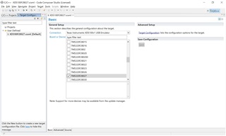
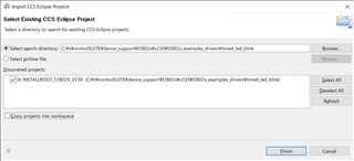
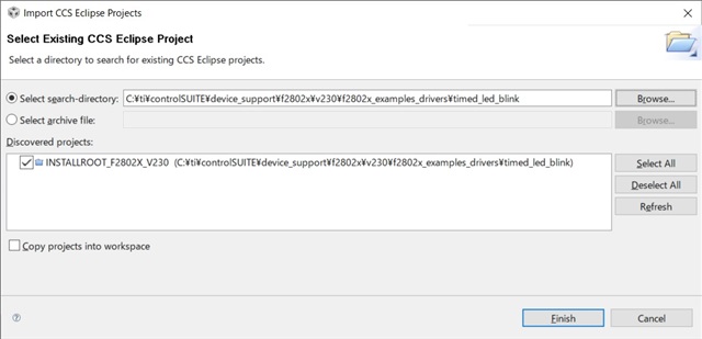
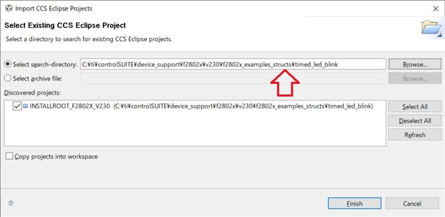
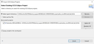
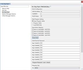
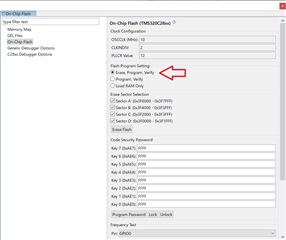
I am trying to debug the TMDSHVRESLLCKIT kit using the project provided in ControlSuite:

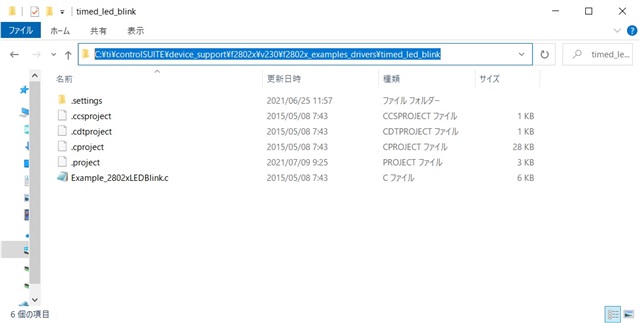
C:\ti\controlSUITE\development_kits\TMDSHVRESLLCKIT_v1.0\HVLLC

I am running on CCSv4 (Code Generation tools: TI v6.0.1)

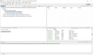
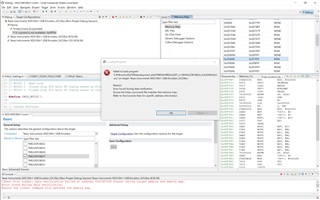
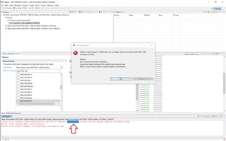
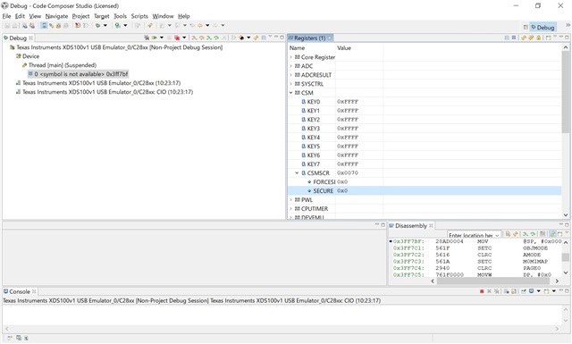
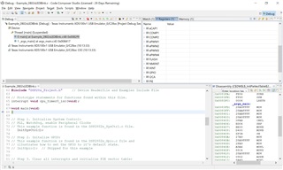
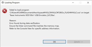
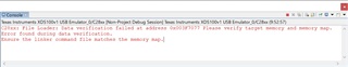
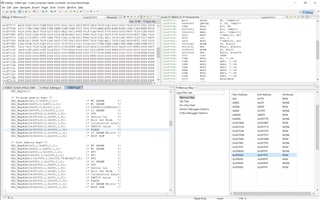
When the CCS [bug] button was pressed, Finally the dialog switched to [Error Launching Debug Session] with the console out below:


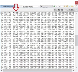
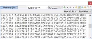
C28xx: File Loader: Data verification failed at address 0x003F706D Please verify target memory and memory map.
Error found during data verification.
Ensure the linker command file matches the memory map.

Jumpers are set up according to the following document:

C:\ti\controlSUITE\development_kits\TMDSHVRESLLCKIT_v1.0\~Docs\HVLLC-SWGuide[R3].pdf


1. Listed below are some of the major connectors and features of the Half-Bridge LLC Resonant DC/DC
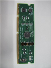
Conversion with Synchronous Rectification board. Insert a F28027 control card into socket [Main]-H1
2. Connect your computer to the board with a USB cable. [M4]-LD1 should turn on.
3. Verify the following jumper settings:
• No jumpers are placed on [Main]-J1,J2.
• Jumpers are placed on [Main]-J3, J4, J5,J6.
• Jumpers are placed on pins 1-2 on [Main]-J7,J8.
• A jumper is placed on [M4]-J4.
4. Connect the 12 VDC power supply to [M3]-JP1 to power the Auxiliary power rail.
5. Connect a 390VDC, 1A (max), power supply across [Main]-BS1, BS2.
6. Connect a 300W (max) load across [Main]-BS3, BS4.
7. Set the power switch [M3]-SW1 so that it is pointed towards the “Ext” label.
→[M3]-LD1 should turn on.
→Green LED should turn on on the controlCARD.

Thanks.

  • This is indication that your target configuration is wrong. I don't see a .ccxml included in the test code, so that means it is likely using one of the "user defined" target configurations. 

    1. go to view-> target configurations. 
    2. Expand "user defined" and then create a new target configuration.
      1. select XDS100v1
      2. select the f2802x device that you are using (likely F28027)
    3. Right click on the target configuration you created and select "launch selected configuration"
    4. Once launched you can load the code using the folder icon in the debug perspective of CCS.

    Let me know if this allows you to load the code.

    Regards,
    Cody 

  • Hi Cody,
    Thank you for your advice.


    I have set up XDS100v1 and F28027.

    When I run the code load, no error is displayed.
    How do I know if I can load the code?

    What do I try next?


    Thanks.

  • Wada-San,

    That looks like the code was able to correctly load onto the device. You can now execute and test the code.

    For some reason you don't have source code associated with the .out file you loaded. This means you won't see the c code which is associated with the assembly code seen in the "Disassembly" window, but this will not affect the code's execution.

        Did you move the .out file outside of the project before loading it into the device? To fix this you can click on the "locate source file" button and navigate to the project's C code.

    Regards,
    Cody 

  • Hi Cody,


    I'm sorry.
    I was failing to select the .out file
    When I correctly selected the .out file and executed code load, the following error message was displayed.

    Are there any other items to check?


    Thanks.

  • Wada-San,

    This error means that you are trying to load the code onto a device the code was not build for. For example If you build a code for an F28027 device and tried to load that code on an F28035 device you would see an error like this.

    I colleague of mine was able to confirm that the HVLLC code will build, load and run on a F28027F device.

    Can you let me know what device you are trying to load the code on to? If possible please send a picture of the controlCARD that you are using.

    Regards,
    Cody 

  • Hi Cody,

    I am using the "TMDSCNCD28027" that came with the "TMDSHVRESLLCKIT".

    I will attach a photo of control CARD.

    Thanks.

  • Wada-San,

    I believe this code should be able to load on that device, but I do not have a device to verify. Have you made any changes to the code before building it?

    I built the files myself, try loading this .out and let me know if it works.HVLLC.out

    Regards,
    Cody 

  • Hi Cody,

    I changed the code according to the following document:

    C:\ti\controlSUITE\development_kits\TMDSHVRESLLCKIT_v1.0\~Docs\HVLLC-SWGuide[R3].pdf

    "From the C/C++ Project tab open the file HVLLC-Settings.h and make sure that INCR_BUILD is set to 1 and save this file."


    I haven't changed any code other than INCR_BUILD.

    When I load the downloaded HVLLC.out, I get the following error:

    The address of the error display has changed from 0x003F706D to 0x003F60DC.
    Does it have anything to do with it?

    Thanks.

  • Wada-San,

    I will need to check what is at that address. I will reply tomorrow.

    Regards,
    Cody 

  • Wada-San,

    The flash addresses are from 0x0037 0000 to 0x0037FF8 so your old error seems to be in the flash. The new error location is in a reserved part of memory, I will need to inquire about this.

    Can you please try loading another example code, like: C:\ti\controlSUITE\device_support\f2802x\v230\f2802x_examples_drivers\timed_led_blink 

    Do you have any issue loading this code?

    If you have issues loading that code, please confirm if the device is unlocked. To do this please read the CSMSCR.SECURE bit and let me know what you see.

    Regards,
    Cody 

  • Hi Cody,

    How do you load the sample code?


    I got an error when I added the project using the following steps.
    “Project → Import Existing CCS/CCE EclipseProject”:

    I checked the CSMSCR.SECURE bit.


    CSMSCR.SECURE = 0

    The device is not locked.

    Thanks.

  • Wada-San,

    CCS is indicating that it cannot find that project file. Please navigate to that location on your PC and verify it exists. It is possible that the path on your PC is different than mine, either due to the install root or having a different version of controlSUITE.

    Regards,
    Cody 

  • Hi Cody,

    I have confirmed that the file exists on my PC.
    Does the specified folder contents match in the next image?

    Does the selected project match with "INSTALLROOT_F2802X_V230"?

    Please let me know if you find the missing file.

    There is also a "timed_led_blink" file in the following location:
    C:\ti\controlSUITE\device_support\f2802x\v230\f2802x_examples_structs\timed_led_blink
    Can I try it with this file?


    Thanks.

  • Wada-San, 

    yes the struct example is OK. Really any example is OK, I just want to see if you can get some code to load onto your hardware.

    I do not know why you are receiving this new error.

    Regards,
    Cody 

  • Hi Cody,

    The project loading error seems to be affected by "macros.ini".
    C:\ti\controlSUITE\device_support\f2802x\v230\f2802x_examples_drivers\timed_led_blink

    The following project succeeded in loading.
    C:\ti\controlSUITE\device_support\f2802x\v129\DSP2802x_examples_ccsv4\timed_led_blink

    When I built the project, I got the following warning:
    warning: entry-point symbol other than "_c_int00" specified: "code_start"

    Setting "Symbol Management" to blank removes the warning.


    The project build and debug were successful without any problems.


    Thanks.

  • OK, good to know that you can run and debug code correctly on this hardware. This means this is likely an issue with the software configuration.

    Lets go back to debugging the HVLLC code which you built on your PC. I believe it said that there was a data verification error in location "0x3f706D". 

    Now since this address is in the middle of flash memory, CCS should be able to program and erase this location. CCS does have a configuration which can be changed however which takes away the ability to erase the flash. Please know that Flash memory can only be written to a 0, and the entire flash sector must be "erased" to return the flash bits to a 1. 

    Go to Tools-> on-chip flash. Please make sure that "Erase and Program" is enabled.

    (your on-chip flash window may look different, the above is for a similar device)

    Regards,
    Cody 

  • Hi Cody,

    I checked Tools-> On-Chip Flash.
    My CCS doesn't have Erase and Program,It is set as follows.

    Flash Program Setting: Erase, Program, Verify

    Thanks.

  • Wada-San,

    that is OK, this is only a minor device difference. 

    1. Please program your code with the "erase, program, and verify" setting. 
    2. Verify the memory address that is having any issue,
    3. Use the memory browser to view the contents of that memory location
    4. use the "erase flash" button
    5. Again use the memory browser to see if the flash location has been set to "0xFFFF"

    Please let me know what the result of steps 3 and 5 are.

    For some reason the device is unable to correctly write to that location, one reason may be that the flash location is not getting erased correctly.

    Regards,
    Cody 

  • Hi Cody,

    1. Please program your code with the "erase, program, and verify" setting. 

    Writing was done with the "erase, program, and verify" settings.


    The following error was displayed:

    C28xx: File Loader: Data verification failed at address 0x003F7077 Please verify target memory and memory map.
    Error found during data verification.
    Ensure the linker command file matches the memory map.

    2. Verify the memory address that is having any issue,
    3. Use the memory browser to view the contents of that memory location

    When I checked 0x003F7077, it was 0xA6C4.

    4. use the "erase flash" button

    Running "Erase Flash" shows success:
    C28xx: Erasing Flash memory...
    C28xx: Operation completed successfully.


    5. Again use the memory browser to see if the flash location has been set to "0xFFFF"

    I ran "erase flash" but it is not set to 0xFFFF.

    For reference, GEL files and Memory Map are displayed.

    Thanks.

  • Wada-San,

    Can you confirm that the screen updated and was not showing old values? Please restart CCS and look at the address once more.

    If the values are still there it seems like you cannot erase your device for some reason. I don't have a good explanation for this, the easiest course of action may to provide a replacement part for the F2802x controlCARD.

    Regards,
    Cody 

  • Hi Cody,

    I restarted CCS and checked the value in the address.
    Not set to 0xFFFF.

    I've tried "Erase Flash" and CCS restart several times, but it's not set to 0xFFFF.

    I don't have another F2802xcontrolCARD and can't replace it.
    Consider getting the F2802xcontrolCARD.

    Thanks.