This thread has been locked.
If you have a related question, please click the "Ask a related question" button in the top right corner. The newly created question will be automatically linked to this question.
Hello,
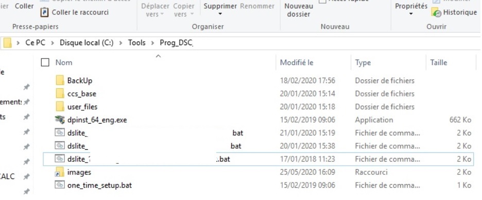
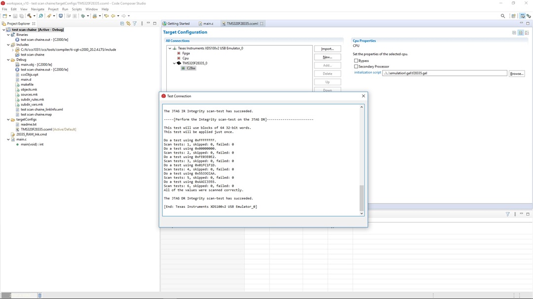
I test DSC on test stand. For that i need to programme IT witch test soft. For that i used the XDS100V2 programmer.
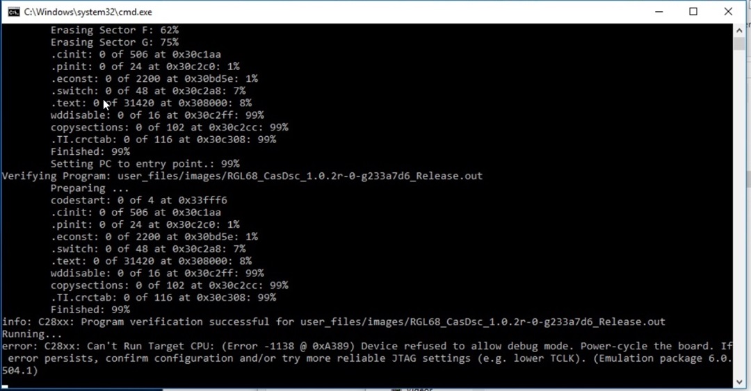
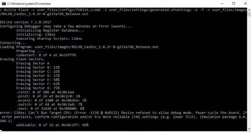
When i programme my DSC an error appears. Error : C28xx: Can't Run Target CPU: (Error -1138 .....
See below the complet error message. In this screen shot the error appears in the middle of the programmation but this problème can appears later
Why sometime the programmation succed and some time i have this error ?
This problème don't appears on each card only on some.
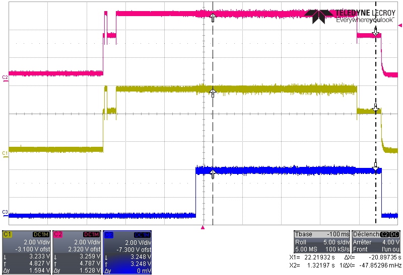
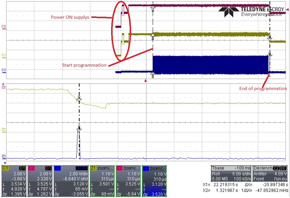
I had monitored the EMU0/EMU1/TCK signal to compare a succeed programmation and a fail programmation.
Below the scope capture when the programmation succeed (pink : EMU0, Yellow : EMU1, Blue : TCK)
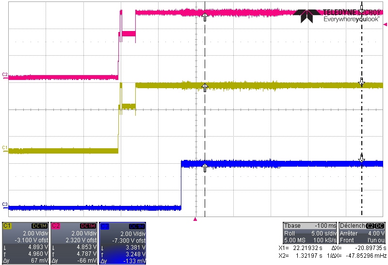
Below the scope capture when the programmation failed
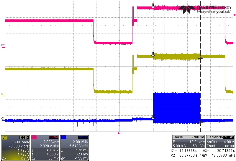
The hard configuration is the same.
The EMU0 and EMU1 doesn't move, it is normal ? I thought this signal have power to change the state of the DSC ("normal mode"/Debug mode).
Does the lenght beetween the XDS100V2 and the DSC cause this trouble ?
I need your help.
Best regard,
Romain
Romain,
A corruption of the flash/or inability to complete the programmation typically occurs when the operations of the flash are interrupted either internally(which isn't typical since most ISR sources are disabled by the flash API) or if there is an external event like XRSn or power fault or as you said the JTAG comms get mis-read/noisy.
You might try and capture TRSTn signals with EMU0/EMU1 as that is what latches the state of those signals into the device.
From your pictures it doesn't appear that there is any noise during the programmation.
I'm not well versed in the DSC application, do you know if we can view/edit the settings? I'm most concerned with seeing if the erase time out is too small. I think we should have it as 10s per sector to be safe.
Alternatively, could we use CCS to erase the device and only ask the DSC utility to program the device? This would let us narrow down the root cause here.
Best,
Matthew
Thank you for your anther Matthew,
I check the IC circuit board and the XRSn is pull to Vcc. I look the supply and it's stable during the programming phase.
I capture à TRSTn (blue) signal with EMU0(pink)/EMU1(yellow) and i don't see any activities it still pull to Vcc. I observe the same behaviour when the programmation succed and it failed. see below
Success
Fail
Can you tell me how can i view/edit the setting ? My folder(who contain .bat and the other file need to programme the DSC device) was creted by uniflash. You can see below this folder.
I don't think the trouble appear when we are in erase phase. Because one time the error appear after the programmation, after the verification
I'm not familiar with CCS how can I erasing my DSC with CCS ? (sorry for this question)
For information CCS reconise my DSC when i start "test connection"
I do the same thing on DSC who seems "dead" after à failed programmation it doesn't talk anymore. When i test connection i have a corruption.
How can i "discorupted" my DSC ? If it's possible ?
Have a nice day,
Best regard,
Romain
Romain,
Can you clarify on the device with corruption, is it corrupt/not connecting through JTAG permanently or just until the next power cycle?
If it is permanent we can use either a comm port boot mode or configure wait boot mode in the ccxml of your emulator by setting EMU0 = low and EMU1 = high in the advanced tab.
Either should keep the device from executing from a secure region(like flash) and disconnecting the emulator. You then will want to look at the CSM passwords at 0x33FFF8 - 0x33FFFF. If you see 0x0000 there then these have been programmed. If the CSM is programmed and the password is unknown there is no way to recover the device.
Back to the last comments of using code composer; I was trying to see if CCS had the same issue programming the .out file as the utility.
If the device is locked, we can't do that experiment though.
Another possibility is that the device doesn't have enough current during programmation on the VDD3VFLP pin. During flash read the current draw on this particular pin is much less. You can see the expected current draw in the datasheet here is 75mA for erase and 35mA for program. You could monitor that rail to make sure it doesn't droop during the flash programming.
Best,
Matthew