This thread has been locked.

If you have a related question, please click the "Ask a related question" button in the top right corner. The newly created question will be automatically linked to this question.

CCS/TMS320F28335: C28xx: Power Failure on Target CPU

Part Number: TMS320F28335

Tool/software: Code Composer Studio

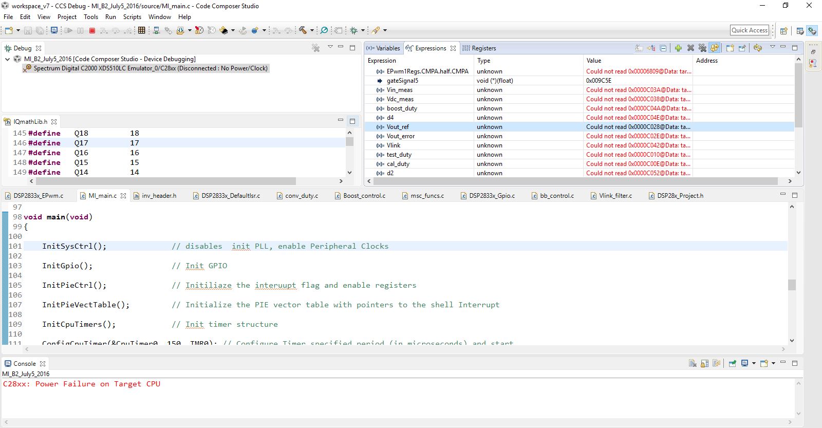
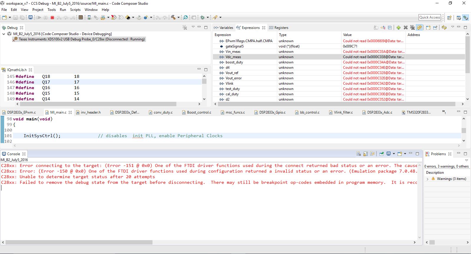
I am using a ezDSP28335 board. When I am running the code, this error occurs in between and I am not able to monitor the signals after this. This usually happens when I am operating my dc-dc boost converter over a certain voltage. In my case, It is able to monitor voltages below 400V and shows this error when my converter goes above 400 V.  The converter seems to operate fine even after this error. I just want to monitor and make changes to some variables in CCS while running. Please tell me what's the issue here.

Thank you.

  • Ankul,
    If the dis-connection appears to be converter voltage related I would suspect switching noise may be dis-rupting the signal. Inside of the .ccxml that configures your target, under the "Advanced" tab, there should be a setting for the JTAG clock. Can you try to slow this down to give the emulator a bit more robustness against any noise?

    Matt
  • I am using a Spectrum Digital C2000 XDS510LC Emulator to connect the ezdsp tmsd320f28335  microprocessor to my computer and it doesn't show a setting to modify the JTAG clock. Do you have any suggestions regarding that?

  • Ankul,
    I see the same when I choose the XDS510LC as the emulator. This eZDSP board has an oboard emulator as well; would it be possible to try that as the connection to see if the problem changes? I beleive you want to pick "Spectrum Digital DSK-EVM-eZDsp onboard USB Emulator"

    Matt
  • Hi Matt,

    I have tried that option too but the problem doesn't change. Is there any other way in which I can do that? Can I use a different JTAG connector and vary the JTAG clock? Or any other option that's available with the ezdsp 28335 board.

    Thanks!

  • Also, I connected my dsp to the system using a XDS100V2 emulator. It runs well till my voltage level hits 400V and after that, it starts having a similar issue as before. The screenshot is attached below with the error. I tried changing the emulator clock and slowed it down but it still had no effect on it.

    Error: 

    C28xx: Error connecting to the target: (Error -151 @ 0x0) One of the FTDI driver functions used during the connect returned bad status or an error. The cause may be one or more of: no XDS100 is plugged in, invalid XDS100 serial number, blank XDS100 EEPROM, missing FTDI drivers, faulty USB cable. Use the xds100serial command-line utility in the 'common/uscif' folder to verify the XDS100 can be located. (Emulation package 7.0.48.0) 
    C28xx: Error: (Error -150 @ 0x0) One of the FTDI driver functions used during configuration returned a invalid status or an error. (Emulation package 7.0.48.0) 
    C28xx: Unable to determine target status after 20 attempts
    C28xx: Failed to remove the debug state from the target before disconnecting.  There may still be breakpoint op-codes embedded in program memory.  It is recommended that you reset the emulator before you connect and reload your program before you continue debugging.
    Please let me know if there are any suggestions regarding this. Thanks!
  • Ankul,
    Past 400V output, is the device still controlling the system, even though there is no emulation connection? I want to make sure we are dealing with an emulation issue or if the device itself is not stable.

    Could you put a scope on one of the controlling PWM pins and XRSn and note any changes once we hit 400V? Assuming the device is still OK, do the same with CCS connected and also add a scope probe to TRSTn and note if TRSTn is getting influenced?

    Best,
    Matthew
  • Hi Matthew,

    The device is still controlling the system even though there is no emulation connection. The code runs perfectly and there are no issues with the system. Its basically an emulation issue I guess. I checked the XRSn pin and it is held at 3.3V. Although, as the voltage increases the noise in the XRSn pin increases. 

    I also tried to run the same code in a 28335 with a docking board (not an ezdsp). I was able to go up to 500V in that case. The emulator in that one is XDS100V2 and the ccs screen gets stuck once it crosses 500V. I have attached a screenshot of the error that I am getting with the new 28335 dsp with docking board. Please let me know if you have any thoughts regarding that.

  • Ankul,

    I think you best bet would be to add isolation to the JTAG signals, both for noise immunity as well as protecting the host PC from damage.

    There is an add on from BH here https://www.blackhawk-dsp.com/store/12134.html  

    We have integrated this to many of our newer control cards/LPs if you want to look at the schematics/implementations like:

    http://www.ti.com/tool/launchxl-f280049c  

    With this LP in particular there is a header to rout the on board XDS110 JTAG to use with an external board.  This may be a more cost attractive option.

    Best,

    Matthew