Part Number: TMS320F28069M
Other Parts Discussed in Thread: CONTROLSUITE
I am trying to port the PFC+Boost controller software from example code : C:\ti\controlSUITE\development_kits\HVMotorCtrl+PfcKit_v2.1\HVACI_Sensorless_PFC_F2803x
to HVMTR-EVM kit using control cardF28069MISO.
The documentation indicates that the _DPL_ISR in file PFC-DPL_ISR.asm is setup to interrupt the MotorInvISR().
From the code listing in HVACI_Sensorless_PFC.c the interrupts are setup as follows:
Interrupt PIE Group PIE Priority CPI INT CPU Priority Vector
ADC_INT1 1 1 1 5 DPL_ISR
ADC_INT2 1 2 1 5 MotorInvISR
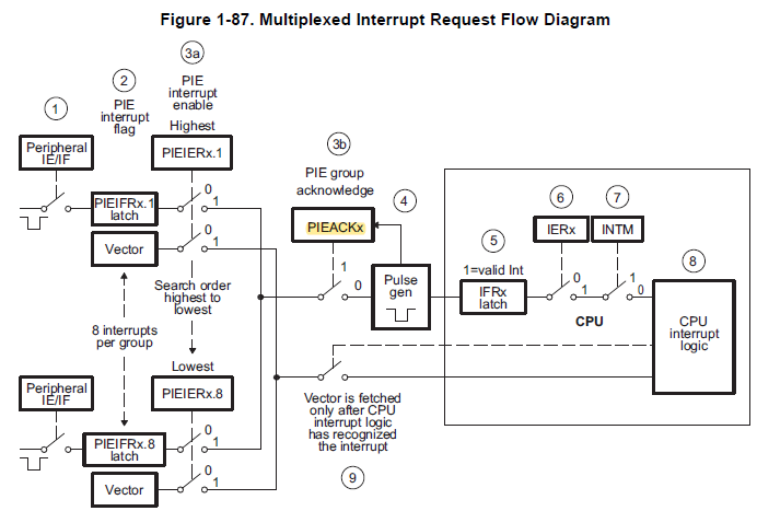
Since both interrupts are coming form PIE group 1 and fed in to CPU INT1, it is not clear to me how the priority logic works. But based on Tms320F28069-FanmilyRef-spruh18h and C28X Interrupt Nesting app-note it seems, to allow DP_ISR to interrupt MotorInvISR you need to
1. clear PIEACK.INT1 to unblock interrupts from PIE group 1 and
2. set IER.INT1 to reenable cpu INT1 which is currently disabled as MotorInvISR is in progress.
I only see EINT at the start of MotorInvISR with comment // Motor ISR is interruptible by the digital power ISR which I believe only clears INTM.
Could you please provide some guidance on how priorities work in this particular case when two interrupts are from the same PIE group?