
- Ask a related questionWhat is a related question?A related question is a question created from another question. When the related question is created, it will be automatically linked to the original question.


Hi Master.
I develop Motor Drive using the TMS320F28388D MCU.
now I am test speed control test base on Example Build 4.
when i see the PID_grando_v3.pdf, there is PID Control Block diagram.
the follow fig.
and The runPID() function in the PID_grando.h was also implemented according to the below diagram
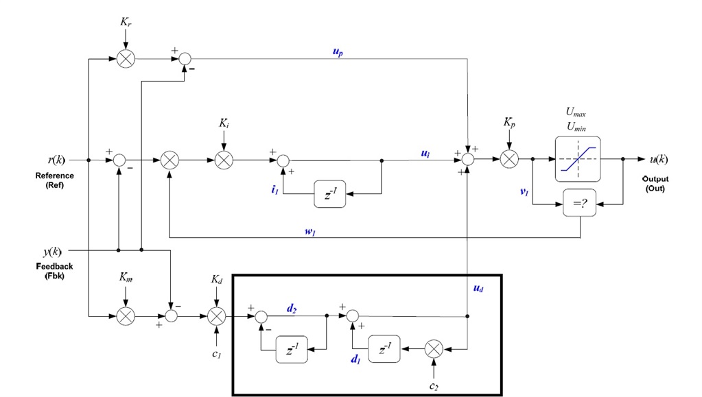
the derivative path (in the black box) diagram is something strange to me
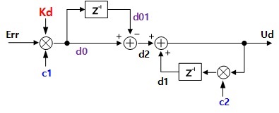
I think the general derivative path as i know is the diagram below
Can it be used it as is or can it be modified ?
(if possible, please explain the black box derivative path)
Thanks.


