This thread has been locked.
If you have a related question, please click the "Ask a related question" button in the top right corner. The newly created question will be automatically linked to this question.
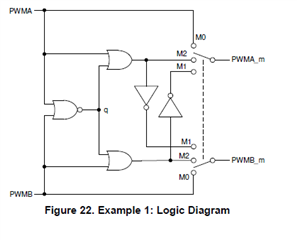
I'm working through the CLB example 1 in "SPRUIR8A–September 2019–Revised April 2020".
Figure 22 below shows the logic diagram implemented in sysconfig using equations 1,2 and 3 below.
I understand how the signals are configured via the muxes in CCS (C code) example project (clb_ex1_combinatorial_logic).
However, the application note does not mention the process of going from the logic diagram to the implemented equations in SYSCONFIG.
Can anyone provide some guidance?
Thanks for your help
Equations in Sysconfig:
Example 1 Logic diagram.
Hi Shiraz,
Thank you for using the E2E forums. The leap from the logic diagram to the equations may seem large, so I can help explain how to transition from the logic diagram to the equation. The first thing that needs to be understood are the CLB inputs (i0, i1, i2, i3). Depending on the version of C2000ware you are using, these inputs are configured either in the main .c file or within SysConfig. The inputs to the CLB are the following:
Inputs i0 and i1 are derived from the mode select. Mode 0 corresponds to 00, mode 1 corresponds to 01, and mode 2 corresponds to 10.
Input i2 corresponds to PWMA and input i3 corresponds to PWMB.
The block diagram outlines equations used in LUT_0 and LUT_1, where the equations are
eq1:= (!i0 & !i1 & i2) | (i0 & !i1 & !(i3 & !(i2 & i3))) | (!i0 & i1 & i2 & !(i2 & i3))
eq2:= (!i0 & !i1 & i3) | (i0 & !i1 & !(i2 & !(i2 & i3))) | (!i0 & i1 & i3 & !(i2 & i3))
Since the two equations are symmetric, we can understand eq1 first and eq2 will follow the same logic. Each block of parentheses corresponds to a mode and is selected using i0 and i1. For example, when mode is 0, i0 and i1 are both 0. Putting these values into the equations, it can be seen that the output reduces to only the first parenthetical block (!0 & !i1 & i2). This means that i2 [PWMA] will be the output of eq1, which corresponds to the mode for unmodified PWMs. Notice that this corresponds to M0 in the logic diagram. Thus, understand that i0 and i1 are only used to select the mode (M0, M1, and M2). The logic diagram translates to i2 and i3 seen in the equations.
Similar logic will apply to the second and third parenthetical blocks. It becomes obvious to see how M1 and M2 translate into the logic equations when we understand that !(i2 & i3) corresponds to q in the logic diagram. Now, you should be able to trace out the logic from the logic diagram and see its translation into the given equations. Please let me know if you need any further explanation.
Regards,
Peter