I encountered this problem when program a new customized board.
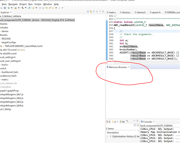
Memory Map Initialization Complete
C28xx_CPU1: GEL Output: ... DCSM Initialization Start ...
C28xx_CPU1: GEL Output: ... DCSM Initialization Done ...
C28xx_CPU1: GEL Output: ... DCSM Initialization Start ...
C28xx_CPU1: GEL Output: ... DCSM Initialization Done ...
C28xx_CPU1: GEL Output: ... DCSM Initialization Start ...
C28xx_CPU1: GEL Output: ... DCSM Initialization Done ...
C28xx_CPU1: Warning: Failed unlocking device (zone 2) after reset.
C28xx_CPU1: Trouble Setting Breakpoint with the Action "Remain Halted" at 0xc0d4: (Error -1066 @ 0xC0D4) Unable to set/clear requested breakpoint. Verify that the breakpoint address is in valid memory. (Emulation package 9.5.0.00143)
C28xx_CPU1: Breakpoint Manager: Retrying with a AET breakpoint
C28xx_CPU1: Error executing PLL configuration algorithm. Operation cancelled. (0x0)
C28xx_CPU1: Perform a debugger reset and execute the Boot-ROM code (click on the RESUME button in CCS debug window) before erasing/loading the Flash. If that does not help to perform a successful Flash erase/load, check the Reset cause (RESC) register, NMI shadow flag (NMISHDFLG) register and the Boot-ROM status register for further debug.
C28xx_CPU1: File Loader: Memory write failed: Unknown error
C28xx_CPU1: GEL: File: C:\Git\Digital_POL\buck_nonpowerSUITE_F28004x\RELEASE\buck_nonpowerSUITE_F28004x.out: Load failed.
Some more details:
1. debugger communication is successful
2. xrs pin is 3.3V
3. GPIO23 and 32 (boot mode pins) are both pulled high
4. VDD output 1.2V
5. another board of the same patch works fine, but i noticed the power drawing from this specific board is lower then the working board.
Thanks!