Hello,
I would like to add HRPWM TBPHSHR capability to my dual active bridge. I am currently only looking at one side of the bridge, so I have two PWM channels with A and B outputs. The A/B outputs on each channel (EPWM1 and EPWM2) are run at 200kHz, ~50% duty (minus deadtime) and complementary to one each other. EPWM1 is the master leg and TBPHS is used to set a phase shift between EPWM1 and EPWM2. The converter works as expected using only TBPHS (no TBPHSHR), but I would like more resolution.
From my understanding if I use the deadtime Active HI complementary setting, I should still get a complementary signal even if HRPWM TBPHSHR is added. I need the deadtime, so I don't think I can use the SELOUTB setting to just output inverted "A" as B. My PWM code is setup below.
What I am noticing is when I added TBPHSHR, I lose waveform symmetry where HR phase is added to the negative cycle, but not the positive cycle. You can see this in the width measurement and its about 10 ns difference when I add the full TBPHSHR range. Autoconvert is on and the timing is correct but something in my setup is causing my PWM2 A/B to no longer be complementary when adding TBPHSHR. Any help is appreciated
 // EPWM Initialization
//-----------------------------------------------------------------------------
void ConfigureEPWM(void)
{
    EALLOW;
    // enable PWM clocks
    CpuSysRegs.PCLKCR2.bit.EPWM1=1;
    CpuSysRegs.PCLKCR2.bit.EPWM2=1;
    CpuSysRegs.PCLKCR2.bit.EPWM3=1;
    CpuSysRegs.PCLKCR2.bit.EPWM4=1;

    CpuSysRegs.PCLKCR0.bit.TBCLKSYNC = 0;
    EDIS;

    EALLOW;
    EPwm1Regs.TBPRD                 =   PWM_TBPRD;          // Set period for ePWMx
    EPwm1Regs.TBCTR                 =   0x0000;             // Clear counter
    EPwm1Regs.TBCTL.bit.CLKDIV      =   TB_DIV1;            // Time-base Clock Prescale Bits
    EPwm1Regs.TBCTL.bit.HSPCLKDIV   =   TB_DIV1;            // High-Speed Time-base Clock Prescale Bits
    EPwm1Regs.TBCTL.bit.SYNCOSEL    =   TB_CTR_ZERO;        // EPWMx is a "master", sync "down-stream"
    EPwm1Regs.TBCTL.bit.PHSEN       =   TB_DISABLE;         // EPWMx is a "master", Do not load the time-base counter at sync
    EPwm1Regs.TBCTL.bit.CTRMODE     =   TB_COUNT_UP;    // UpCount Mode
    EPwm1Regs.CMPA.bit.CMPA         =   PWM_TBPRDdiv2;      // Start at a duty cycle of approximately 50%
    EPwm1Regs.CMPCTL.bit.LOADBMODE  =   CC_CTR_PRD;    // Load at both the top and bottom of the carrier
    EPwm1Regs.CMPCTL.bit.LOADAMODE  =   CC_CTR_PRD;    // Load at both the top and bottom of the carrier
    EPwm1Regs.AQCTLA.bit.CAU        =   UPAQ;                //Set   PWMxA on event A, up count
    EPwm1Regs.AQCTLA.bit.PRD        =   DNAQ;               // Clear PWMxA on zero
    EPwm1Regs.AQCTLA.bit.CBU        =   UPAQ;                //Set   PWMxA on event B, up count

    EPwm1Regs.DBCTL.bit.HALFCYCLE   =   1;                  // Half cycle clocking enabled. The dead-band counters are clocked at TBCLK*2
    EPwm1Regs.DBCTL.bit.POLSEL      =   DB_ACTV_HIC;        // Active HI complementary
    EPwm1Regs.DBCTL.bit.OUT_MODE    =   DB_FULL_ENABLE;     // Enable Dead-band module on both rising and falling edges
    EPwm1Regs.DBRED.bit.DBRED       =   DEADBAND;           // Rising Edge Deadband
    EPwm1Regs.DBFED.bit.DBFED       =   DEADBAND;           // Falling Edge Deadband
    EPwm1Regs.TZEINT.bit.CBC        =   0;
    EPwm1Regs.TZSEL.bit.OSHT1       =   0;                  // Disable TZ1 as one one-shot trip source
    EPwm1Regs.TZCTL.bit.TZA         =   TZ_FORCE_LO;        // TZ1 forces A output lo
    EPwm1Regs.TZCTL.bit.TZB         =   TZ_FORCE_LO;        // TZ1 forces B output lo
    //    EPwm1Regs.TZEINT.bit.OST        =   1;                  // Enable TZ interrupt

    EPwm1Regs.ETSEL.bit.SOCAEN      =   1;                  // Enable SOC on A group
    EPwm1Regs.ETSEL.bit.SOCASEL     =   ET_CTR_ZERO;        // Select SOC A on EPWM1 Timer Zero
    EPwm1Regs.ETPS.bit.SOCAPRD      =   ET_2ND;             // Generate pulse on every event
#if ENHRPWM == 1
    EPwm1Regs.HRCNFG.all = 0x0;
    EPwm1Regs.HRCNFG.bit.EDGMODE  = HR_BEP;  // MEP control on falling edge
    EPwm1Regs.HRCNFG.bit.EDGMODEB = HR_BEP; // MEP control on falling edge
    EPwm1Regs.HRCNFG.bit.CTLMODE  = HR_PHS;
    EPwm1Regs.HRCNFG.bit.CTLMODEB = HR_PHS;
    EPwm1Regs.HRCNFG.bit.HRLOAD  = HR_CTR_ZERO_PRD;
    EPwm1Regs.HRCNFG.bit.AUTOCONV = 1;      // Enable auto-conversion                                             // logic
    EPwm1Regs.HRPCTL.bit.TBPHSHRLOADE = 1;
#endif

    EDIS;
//
    EALLOW;
    // Assumes ePWM clock is already enabled
    EPwm2Regs.TBPRD                 =   PWM_TBPRD;          // Set period for ePWMx
    EPwm2Regs.TBCTR                 =   0x0000;             // Clear counter
    EPwm2Regs.TBCTL.bit.CLKDIV      =   TB_DIV1;            // Time-base Clock Prescale Bits
    EPwm2Regs.TBCTL.bit.HSPCLKDIV   =   TB_DIV1;            // High-Speed Time-base Clock Prescale Bits
    EPwm2Regs.TBCTL.bit.SYNCOSEL    =   TB_SYNC_IN;         // EPWMx is a "slave", sync flow-through
    EPwm2Regs.TBCTL.bit.PHSEN       =   TB_ENABLE;          // EPWMx is a "slave", Load the time-deg counter from TBPHS at sync
    EPwm2Regs.TBPHS.bit.TBPHS       =   PWM_TBPRDdiv2+2;             // Start phase shift aligned to EPWM1
    EPwm2Regs.TBPHS.bit.TBPHSHR     =   1<<8;
    EPwm2Regs.TBCTL.bit.CTRMODE     =   TB_COUNT_UP;        // Up-Down Count Mode
    EPwm2Regs.CMPA.bit.CMPA         =   PWM_TBPRDdiv2;      // Start at a duty cycle of approximately 50%
    EPwm2Regs.CMPB.bit.CMPB         =   PWM_TBPRDdiv2+5;    // Start at a duty cycle of approximately 50%
    EPwm2Regs.CMPCTL.bit.LOADBMODE  =   CC_CTR_PRD;         // Load at both the top and bottom of the carrier
    EPwm2Regs.CMPCTL.bit.SHDWBMODE  =   CC_IMMEDIATE;       // CMPB is a safeguard value which we want updated ASAP, overwrites LOADBMODE
    EPwm2Regs.CMPCTL.bit.LOADAMODE  =   CC_CTR_PRD;         // Load at both the top and bottom of the carrier

    EPwm2Regs.AQCTLA.bit.CAU        =   DNAQ;               //Clear   PWMxA on event A, up count
    EPwm2Regs.AQCTLA.bit.CBU        =   DNAQ;               //Clear   PWMxA on event B, up count
    EPwm2Regs.AQCTLA.bit.PRD        =   UPAQ;               // Set PWMxA on zero

    EPwm2Regs.DBCTL.bit.HALFCYCLE   =   1;                  // Half cycle clocking enabled. The dead-band counters are clocked at TBCLK*2
    EPwm2Regs.DBCTL.bit.POLSEL      =   DB_ACTV_HIC;        // Active HI complementary
    EPwm2Regs.DBCTL.bit.OUT_MODE    =   DB_FULL_ENABLE;     // Enable Dead-band module on both rising and falling edges
    EPwm2Regs.DBRED.bit.DBRED       =   DEADBAND;           // Rising Edge Deadband
    EPwm2Regs.DBFED.bit.DBFED       =   DEADBAND;           // Falling Edge Deadband
    EPwm2Regs.TZEINT.bit.CBC        =   0;
    EPwm2Regs.TZSEL.bit.OSHT1       =   0;                  // Disable TZ1 as one one-shot trip source
    EPwm2Regs.TZCTL.bit.TZA         =   TZ_FORCE_LO;        // TZ1 forces A output lo
    EPwm2Regs.TZCTL.bit.TZB         =   TZ_FORCE_LO;        // TZ1 forces B output lo

#if ENHRPWM == 1
    EPwm2Regs.HRCNFG.all = 0x0;
    EPwm2Regs.HRCNFG.bit.EDGMODE  = HR_BEP;  // MEP control on falling edge
    //EPwm2Regs.HRCNFG.bit.EDGMODEB = HR_BEP;  // MEP control on falling edge
    EPwm2Regs.HRCNFG.bit.CTLMODE  = HR_PHS;
    //EPwm2Regs.HRCNFG.bit.CTLMODEB = HR_PHS;
    EPwm2Regs.HRCNFG.bit.HRLOAD  = HR_CTR_ZERO_PRD;
    EPwm2Regs.HRCNFG.bit.AUTOCONV = 1;      // Enable auto-conversion
    EPwm2Regs.HRPCTL.bit.TBPHSHRLOADE = 1;
#endif

    EDIS;

    EALLOW;
    CpuSysRegs.PCLKCR0.bit.TBCLKSYNC = 1;
    EDIS;

}
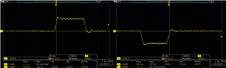
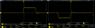
Zoomed Out figure showing symmetric waveforms when TBPHSHR = 0

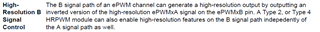
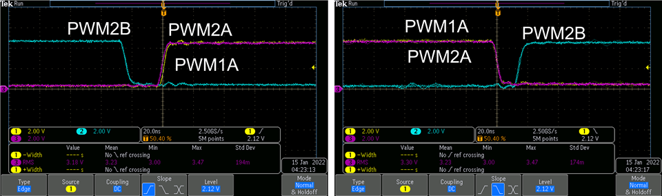
Zoomed in when TBPHSHR = 0
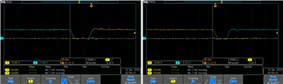
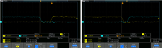
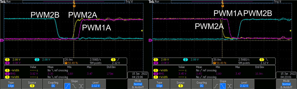
Zoomed in when TBPHSHR is close to max