
- Ask a related questionWhat is a related question?A related question is a question created from another question. When the related question is created, it will be automatically linked to the original question.
This thread has been locked.
If you have a related question, please click the "Ask a related question" button in the top right corner. The newly created question will be automatically linked to this question.
Hello,
I am working on a TMS320F28388D CPU located on the TMDSCNCD28388D evaluation board. The processor contains 3 CPU cores: CPU1 (C2000) / CPU2 (C2000) / CM (Connectivity Manager - ARM Cortex-M4).
It seems that the CPU1 core has no direct access to the flash memory of the CM core. I assume that I have to boot the CM core first via CPU1 and afterwards exchange data between the cores over the IPC interface, which the CM can then finally store on his flash. Therefore, I believe that I have to first boot the CM via a boot-mode called ‘Copy from IPC Message RAM and boot to RAM’ (see reference manual spruii0c.pdf table ‘5-1. Boot System Overview’).
My plan would now be, that I am writing a CPU1 application (e.g. based on the blinking LED example), which boots the CM in this ‘Copy from IPC Message RAM and boot to RAM’ boot mode and I would like to add the CM boot image as an array to the CPU1 project. I would like to take also the blinking LED example for the CM core in build configuration CM_RAM (the whole application resides on the RAM memory) and check that the CM core is running that blinking LED application.
I have the following questions
1) Can you please confirm that CPU1 has no ability to directly access the Flash of the CM?
2) Is my approach correct, that I first have to boot the CM via the ‘Copy from IPC Message RAM and boot to RAM’ boot mode? Afterwards that CM application can continue to communicate with the CPU1 core over the IPC message RAM and access the CM-flash.
3) Is there a TI example project available, which shows how the CPU1 boots the CM over IPC, referred to as ‘Copy from IPC Message RAM and boot to RAM’ inside table 5-1 of the file spruii0c.pdf?
4) Is an application note for ‘Copy from IPC Message RAM and boot to RAM’ available, since the information inside chapter 5.7.7.1.6 of the reference manual spruii0c.pdf is not detailed enough? In this chapter it looks like I can write only one time a CM boot-loader image of max. 2[kword] to the IPC message RAM, which is copied by the CM to his RAM and executed. This would be of course a limitation for the size of the CM image.
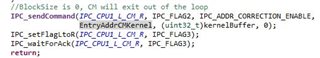
5) I also see no information in which format the boot-image has to be, so how do I need to set up the ‘Arm Hex Utility’ tool inside the CM project for this boot mode?
6) In case that there is no further documentation or example project: Is the CM ROM boot-loader source code available, in order to learn from that code how the ‘Copy from IPC Message RAM and boot to RAM’ boot mode is working from the CM view? If so, where can I find it?
Thanks,
Inno
Hello,
1. Correct, CPU1 cannot directly access the Flash of CM.
2. This is correct.
3. There is a SCI flash kernel example for F2838x that shows how to use this boot mode, located at C2000Ware_4_00_00_00\driverlib\f2838x\examples\c28x_cm\flash_kernel
4. I don't think there is an app note specifically for this boot mode, but there is an app note for the flash kernel: www.ti.com/lit/sprabv4
5. Please refer to the linked app note.
6. There are no bootloaders for CM, please refer to the example.
Thanks
Anu

Hello Anu,
I had a quick look at the app note. Let me see if I get it right:
The app note you mentioned in point 4 refers also to the 'C2000Ware_4_00_00_00\driverlib\f2838x\examples\c28x_cm\flash_kernel' example. The example project offers basically a lot of options to communicate with different Cores and their corrsponding flash memory over UART.
That means that a certain part of that project uses also the 'Copy from IPC Message RAM and boot to RAM’ method I am looking for and this happens at a specific point in time when running the example and sending CM images over UART.
I will study the app note first and afterwards run the example. Thanks for point me to the example project and the app note.
Please allow me to ask one addition question although I may get the answer also out of the example project. The CPU1 -> CM message buffer is of size 2[kword] = 4[kByte]. But the internal RAM memory of the CM, where an application image may reside, is of course bigger. Is it possible that I download a CM RAM application of larger size than 2[kword] in chunks over the CPU1 -> CM message RAM as part of the ‘Copy from IPC Message RAM and boot to RAM’ procedure? Or does the CM copy only one 'packet' from the CPU1 -> CM message RAM and tries to jump right away to the CM application, which means that the max. size of a RAM application to be used for the 'Copy from IPC Message RAM and boot to RAM’ procedure is limited to 2[kwords]?
Regards,
Inno
Hello,
The app note you mentioned in point 4 refers also to the 'C2000Ware_4_00_00_00\driverlib\f2838x\examples\c28x_cm\flash_kernel' example. The example project offers basically a lot of options to communicate with different Cores and their corrsponding flash memory over UART.
More specifically, the example shows how to perform firmware upgrades for CPU1 and CM via SCI.
That means that a certain part of that project uses also the 'Copy from IPC Message RAM and boot to RAM’ method I am looking for and this happens at a specific point in time when running the example and sending CM images over UART.
Yes, you will see the method used in the CPU1 project. One point I would like to clarify is that the CPU1 SCI module is used for both CPU1 and CM, the CM UART module is not used. CPU1 receives data over SCI which it sends to CM via IPC Message RAM, and CM takes this information to perform its kernel operations.
Is it possible that I download a CM RAM application of larger size than 2[kword] in chunks over the CPU1 -> CM message RAM as part of the ‘Copy from IPC Message RAM and boot to RAM’ procedure?
This is correct, you can copy over the CM RAM application in chunks. This is demonstrated in the Flash kernel example - the CM flash kernel which resides in RAM is copied over in chunks.
Thanks
Anu
Hi Anu,
after learning the flash kernel example, I understand that the important functions to look at are:
Especially the ‘copyDataToCPU1ToCMMSGRAM’ function is the one that sends the CM kernel RAM-image in chunks to the CM over the IPC interface.
I have a question about the way, how the CPU1 sends the data to the CM during boot via ‘IPC_sendCommand’ or terminates the process.
1) Where is the copy protocol described?
For example, where is it described that during copying the data, the IPCSENDCOM/IPCREVCOM register needs to hold destination address where the data needs to be copied to CM RAM. Or that IPCSENDADDR/IPCRECVDATE holds the kernelBuffer[] array address inside the message RAM. Or that IPCSENDDATA/IPCRECVDATE holds the number of bytes.
See here:
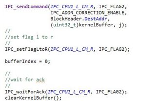
2) And where is it described that the process is terminated like this:
That means IPCSENDCOM/IPCREVCOM register needs to hold the entry point address and that IPCSENDDATA/IPCRECVDATE value 0 means ‘jump to application image of entry point inside IPCSENDCOM/IPCREVCOM’.
I did not find some kind of a flow chart or anything else for the 'CPU1 -> CM IPC copy and boot to RAM' process within the CPU reference manual, which describes the process in detail.
3) BTW, is it required that for copying data the IPC FLAG2 is used and for terminating FLAG3? Or can I decide which flags to use and the ROM boot-loader simply polls all IPC request flags?
Thanks,
Inno
Hello,
The copy protocol/termination process is described in the app note linked in a previous reply, specifically section 5.2.2. The flags can be determined by you, it does not need to be flags 2 and 3. One point I want to clarify, this is a secondary bootloader that runs in RAM, not ROM.
Thanks
Anu
Hello Anu,
I am really sorry, but I am still struggeling a bit. Let me explain what I tried to do after learning the flash kernel example (at least parts of it). I compiled a blinking LED example project for the CM core in build configuration RAM and set the arm hex utility as follows:
Afterwards I took the file, which was generated by the arm hex utility, and created an array from it (I removed the start of text / end of text characters 0x02/ 0x03), which I added afterwards to a CPU1 blinking LED project in build configuration FLASH (because otherwise I am running out of RAM memory). See here my code:
#include "device.h"
uint8_t Boot_IMG[]=
{
0x08, 0xAA, 0x00, 0x00, 0x00, 0x00, 0x00, 0x00, 0x00, 0x00, 0x00, 0x00, 0x00, 0x00, 0x00, 0x00, 0x00, 0x00, 0x20, 0x00, 0x0B, 0x09, 0x00, 0x06,
0x20, 0x00, 0x08, 0x00, 0x00, 0xF0, 0x82, 0xB9, 0x70, 0x47,
0x01, 0x40, 0x20, 0x00, 0x0C, 0x00, 0x00, 0xC2, 0xFF, 0x1F, 0x01, 0x08, 0x00, 0x20, 0xA9, 0x0B, 0x00, 0x20, 0x47, 0x0B, 0x00, 0x20, 0x17, 0x0A,
0x00, 0x20, 0x17, 0x0A, 0x00, 0x20, 0x17, 0x0A, 0x00, 0x20, 0x00, 0x00, 0x00, 0x00, 0x00, 0x00, 0x00, 0x00, 0x00, 0x00, 0x00, 0x00, 0x00, 0x00,
0x00, 0x00, 0x17, 0x0A, 0x00, 0x20, 0x17, 0x0A, 0x00, 0x20, 0x00, 0x00, 0x00, 0x00, 0x17, 0x0A, 0x00, 0x20, 0x17, 0x0A, 0x00, 0x20, 0x17, 0x0A,
0x00, 0x20, 0x17, 0x0A, 0x00, 0x20, 0x17, 0x0A, 0x00, 0x20, 0x17, 0x0A, 0x00, 0x20, 0x17, 0x0A, 0x00, 0x20, 0x17, 0x0A, 0x00, 0x20, 0x17, 0x0A,
0x00, 0x20, 0x17, 0x0A, 0x00, 0x20, 0x17, 0x0A, 0x00, 0x20, 0x17, 0x0A, 0x00, 0x20, 0x17, 0x0A, 0x00, 0x20, 0x17, 0x0A, 0x00, 0x20, 0x17, 0x0A,
0x00, 0x20, 0x17, 0x0A, 0x00, 0x20, 0x17, 0x0A, 0x00, 0x20, 0x17, 0x0A, 0x00, 0x20, 0x17, 0x0A, 0x00, 0x20, 0x17, 0x0A, 0x00, 0x20, 0x17, 0x0A,
0x00, 0x20, 0x17, 0x0A, 0x00, 0x20, 0x17, 0x0A, 0x00, 0x20, 0x17, 0x0A, 0x00, 0x20, 0x17, 0x0A, 0x00, 0x20, 0x17, 0x0A, 0x00, 0x20, 0x17, 0x0A,
0x00, 0x20, 0x17, 0x0A, 0x00, 0x20, 0x17, 0x0A, 0x00, 0x20, 0x17, 0x0A, 0x00, 0x20, 0x17, 0x0A, 0x00, 0x20, 0x17, 0x0A, 0x00, 0x20, 0x17, 0x0A,
0x00, 0x20, 0x17, 0x0A, 0x00, 0x20, 0x17, 0x0A, 0x00, 0x20, 0x17, 0x0A, 0x00, 0x20, 0x17, 0x0A, 0x00, 0x20, 0x17, 0x0A, 0x00, 0x20, 0x17, 0x0A,
0x00, 0x20, 0x17, 0x0A, 0x00, 0x20, 0x17, 0x0A, 0x00, 0x20, 0x17, 0x0A, 0x00, 0x20, 0x17, 0x0A, 0x00, 0x20, 0x17, 0x0A, 0x00, 0x20, 0x17, 0x0A,
0x00, 0x20, 0x17, 0x0A, 0x00, 0x20, 0x17, 0x0A, 0x00, 0x20, 0x17, 0x0A, 0x00, 0x20, 0x17, 0x0A, 0x00, 0x20, 0x17, 0x0A, 0x00, 0x20, 0x17, 0x0A,
0x00, 0x20, 0x17, 0x0A, 0x00, 0x20, 0x17, 0x0A, 0x00, 0x20, 0x17, 0x0A, 0x00, 0x20, 0x17, 0x0A, 0x00, 0x20, 0x17, 0x0A, 0x00, 0x20, 0x17, 0x0A,
0x00, 0x20, 0x17, 0x0A, 0x00, 0x20, 0x17, 0x0A, 0x00, 0x20, 0x17, 0x0A, 0x00, 0x20, 0x17, 0x0A, 0x00, 0x20, 0x17, 0x0A, 0x00, 0x20, 0x17, 0x0A,
0x00, 0x20, 0x17, 0x0A, 0x00, 0x20, 0x17, 0x0A, 0x00, 0x20, 0x17, 0x0A, 0x00, 0x20,
0x00, 0x06, 0x1F, 0xFF, 0xE0, 0x00, 0x40, 0x1E, 0xFD, 0xD1, 0x70, 0x47,
0x00, 0x18, 0x1F, 0xFF, 0xE0, 0x08, 0xAF, 0x09, 0x00, 0x20, 0x93, 0x0B, 0x00, 0x20, 0x00, 0x01, 0x00, 0x00, 0x00, 0xFF, 0xF0, 0x00, 0x10, 0xE0,
0xFF, 0x1F, 0x00, 0xC0, 0x00, 0x20,
0x03, 0xA2, 0x20, 0x00, 0x08, 0x08, 0x00, 0x2A, 0x4A, 0xD0, 0x5F, 0xEA, 0x00, 0x0C, 0x8B, 0x07, 0x1C, 0xD1, 0x83, 0x07, 0x22, 0xD1, 0x10, 0x2A,
0x08, 0xD3, 0x70, 0xB4, 0x10, 0x3A, 0x78, 0xC9, 0x78, 0xC0, 0x10, 0x3A, 0xFB, 0xD2, 0x70, 0xBC, 0x10, 0x32, 0x38, 0xD0, 0x04, 0x2A, 0x2C, 0xD3,
0x08, 0x2A, 0x05, 0xD3, 0x0C, 0x2A, 0x24, 0xBF, 0x08, 0xC9, 0x08, 0xC0, 0x08, 0xC9, 0x08, 0xC0, 0x08, 0xC9, 0x08, 0xC0, 0x92, 0x07, 0x2A, 0xD0,
0x92, 0x0F, 0x22, 0xE0, 0x0B, 0x78, 0x03, 0x70, 0x49, 0x1C, 0x40, 0x1C, 0x52, 0x1E, 0x22, 0xD0, 0x8B, 0x07, 0xF7, 0xD1, 0xC3, 0x07, 0x14, 0xD1,
0x83, 0x07, 0xD8, 0xD0, 0x12, 0x1F, 0x12, 0xD3, 0x08, 0xC9, 0x03, 0x80, 0x1B, 0x0C, 0x43, 0x80, 0x00, 0x1D, 0x12, 0x1F, 0xF8, 0xD2, 0x0A, 0xE0,
0x08, 0xC9, 0x03, 0x70, 0x1B, 0x0A, 0x43, 0x70, 0x1B, 0x0A, 0x83, 0x70, 0x1B, 0x0A, 0xC3, 0x70, 0x00, 0x1D, 0x12, 0x1F, 0xF4, 0xD2, 0x12, 0x1D,
0x05, 0xD0, 0x0B, 0x78, 0x03, 0x70, 0x49, 0x1C, 0x40, 0x1C, 0x52, 0x1E, 0xF9, 0xD1, 0x60, 0x46, 0x70, 0x47, 0x00, 0xB5, 0xAD, 0xF1, 0x14, 0x0D,
0x01, 0x91, 0x00, 0x90, 0x00, 0x98, 0x00, 0xF0, 0x3C, 0xF9, 0x18, 0xB9, 0x0D, 0xA0, 0xE9, 0x21, 0x00, 0xF0, 0x63, 0xF9, 0x00, 0x99, 0x1C, 0x48,
0x49, 0x09, 0x00, 0xEB, 0x01, 0x10, 0x02, 0x90, 0x00, 0x98, 0x01, 0x21, 0x00, 0xF0, 0x1F, 0x00, 0x81, 0x40, 0x03, 0x91, 0x01, 0x98, 0x18, 0xB9,
0x03, 0x98, 0x02, 0x99, 0x88, 0x60, 0x02, 0xE0, 0x03, 0x98, 0x02, 0x99, 0x48, 0x60, 0x05, 0xB0, 0x00, 0xBD, 0x43, 0x3A, 0x2F, 0x74, 0x69, 0x2F,
0x63, 0x32, 0x30, 0x30, 0x30, 0x2F, 0x43, 0x32, 0x30, 0x30, 0x30, 0x57, 0x61, 0x72, 0x65, 0x5F, 0x33, 0x5F, 0x30, 0x34, 0x5F, 0x30, 0x30, 0x5F,
0x30, 0x30, 0x2F, 0x64, 0x72, 0x69, 0x76, 0x65, 0x72, 0x6C, 0x69, 0x62, 0x2F, 0x66, 0x32, 0x38, 0x33, 0x38, 0x78, 0x2F, 0x64, 0x72, 0x69, 0x76,
0x65, 0x72, 0x6C, 0x69, 0x62, 0x5F, 0x63, 0x6D, 0x2F, 0x67, 0x70, 0x69, 0x6F, 0x2E, 0x68, 0x00, 0xC0, 0x46, 0x00, 0x30, 0x08, 0x40, 0x08, 0xB5,
0x00, 0x20, 0x00, 0xF0, 0x9E, 0xF8, 0x4F, 0xF4, 0x80, 0x60, 0x00, 0xF0, 0x9A, 0xF8, 0x4F, 0xF4, 0x00, 0x60, 0x00, 0xF0, 0x96, 0xF8, 0x4F, 0xF4,
0x40, 0x60, 0x00, 0xF0, 0x92, 0xF8, 0x01, 0x20, 0x00, 0xF0, 0x8F, 0xF8, 0x40, 0xF2, 0x01, 0x20, 0x00, 0xF0, 0x8B, 0xF8, 0x40, 0xF2, 0x01, 0x40,
0x00, 0xF0, 0x87, 0xF8, 0x40, 0xF2, 0x01, 0x50, 0x00, 0xF0, 0x83, 0xF8, 0x40, 0xF6, 0x01, 0x00, 0x00, 0xF0, 0x7F, 0xF8, 0x02, 0x20, 0x00, 0xF0,
0x7C, 0xF8, 0x4F, 0xF4, 0x81, 0x70, 0x00, 0xF0, 0x78, 0xF8, 0x40, 0xF2, 0x02, 0x20, 0x00, 0xF0, 0x74, 0xF8, 0x40, 0xF2, 0x02, 0x40, 0x00, 0xF0,
0x70, 0xF8, 0x40, 0xF2, 0x02, 0x60, 0x00, 0xF0, 0x6C, 0xF8, 0x40, 0xF6, 0x02, 0x00, 0x00, 0xF0, 0x68, 0xF8, 0x08, 0xBD, 0xF8, 0xB5, 0x84, 0x46,
0x40, 0xF6, 0xFF, 0x74, 0x1C, 0xF8, 0x01, 0x3B, 0x00, 0x22, 0x10, 0xE0, 0x48, 0x1B, 0x40, 0x1E, 0x10, 0xF8, 0x01, 0x5B, 0x7F, 0x1E, 0x01, 0xF8,
0x01, 0x5B, 0xF9, 0xD1, 0x03, 0xE0, 0x1C, 0xF8, 0x01, 0x0B, 0x01, 0xF8, 0x01, 0x0B, 0x52, 0x1C, 0x5B, 0x08, 0x08, 0x2A, 0xEA, 0xDA, 0x58, 0x08,
0xF5, 0xD2, 0x1C, 0xF8, 0x01, 0x0B, 0x1C, 0xF8, 0x01, 0x5B, 0x05, 0xF0, 0x0F, 0x07, 0xFF, 0x1C, 0xC5, 0xF3, 0x03, 0x15, 0x12, 0x2F, 0x45, 0xEA,
0x00, 0x15, 0x08, 0xD1, 0x1C, 0xF8, 0x01, 0x6B, 0x30, 0x0A, 0x24, 0xBF, 0x1C, 0xF8, 0x01, 0x0B, 0x60, 0xF3, 0xDF, 0x16, 0xBF, 0x19, 0xAC, 0x42,
0xD4, 0xD1, 0xF8, 0xBD, 0xFE, 0xE7, 0x08, 0xB5, 0x00, 0xF0, 0x95, 0xF8, 0x22, 0x20, 0x00, 0x21, 0xFF, 0xF7, 0x3F, 0xFF, 0x12, 0x48, 0x00, 0x68,
0x08, 0x28, 0x03, 0xDA, 0x11, 0x48, 0xFD, 0xF7, 0xE6, 0xFA, 0x02, 0xE0, 0x10, 0x48, 0xFD, 0xF7, 0xE2, 0xFA, 0x22, 0x20, 0x01, 0x21, 0xFF, 0xF7,
0x30, 0xFF, 0x0A, 0x48, 0x00, 0x68, 0x08, 0x28, 0x03, 0xDA, 0x09, 0x48, 0xFD, 0xF7, 0xD7, 0xFA, 0x02, 0xE0, 0x08, 0x48, 0xFD, 0xF7, 0xD3, 0xFA,
0x05, 0x49, 0x08, 0x68, 0x40, 0x1C, 0x08, 0x60, 0x03, 0x48, 0x02, 0x49, 0x00, 0x68, 0x00, 0xF0, 0x0F, 0x00, 0x08, 0x60, 0xD6, 0xE7, 0x00, 0xC0,
0x00, 0x20, 0x32, 0xE4, 0x3D, 0x01, 0x67, 0xC8, 0x7B, 0x02, 0x1C, 0xB5, 0xAD, 0xF8, 0x00, 0x00, 0xBD, 0xF8, 0x00, 0x00, 0x00, 0xF0, 0x1F, 0x00,
0x80, 0x00, 0xAD, 0xF8, 0x02, 0x00, 0xBD, 0xF8, 0x00, 0x00, 0x00, 0xF4, 0xF8, 0x50, 0x00, 0x0A, 0xAD, 0xF8, 0x04, 0x00, 0x07, 0x49, 0x07, 0x4A,
0xBD, 0xF8, 0x02, 0x00, 0xBD, 0xF8, 0x04, 0x40, 0x40, 0x18, 0x03, 0x68, 0x01, 0x21, 0xA1, 0x40, 0x19, 0x43, 0x0A, 0x43, 0x02, 0x60, 0x1C, 0xBD,
0xC0, 0x46, 0x00, 0xC0, 0x0F, 0x40, 0x00, 0x00, 0x34, 0x56, 0xB0, 0xB5, 0x0C, 0x48, 0x0C, 0x4D, 0xA8, 0x42, 0x10, 0xD0, 0x0C, 0x48, 0x0C, 0x4C,
0xA0, 0x42, 0x0C, 0xD0, 0x00, 0x1B, 0x08, 0x3C, 0xC7, 0x10, 0x54, 0xF8, 0x08, 0x0F, 0x01, 0x78, 0x55, 0xF8, 0x21, 0x20, 0x61, 0x68, 0x40, 0x1C,
0x90, 0x47, 0x7F, 0x1E, 0xF5, 0xD1, 0x00, 0xBF, 0x00, 0xBF, 0xB0, 0xBD, 0xC0, 0x46, 0x10, 0xE0, 0xFF, 0x1F, 0x08, 0xE0, 0xFF, 0x1F, 0x20, 0xE0,
0xFF, 0x1F, 0x18, 0xE0, 0xFF, 0x1F, 0x07, 0x48, 0x80, 0xF3, 0x08, 0x88, 0x00, 0xBF, 0x00, 0xBF, 0x00, 0xF0, 0x45, 0xF8, 0x08, 0xB1, 0xFF, 0xF7,
0xD4, 0xFF, 0x00, 0x20, 0xFF, 0xF7, 0x7B, 0xFF, 0x01, 0x20, 0x00, 0xF0, 0x3E, 0xF8, 0x00, 0xC2, 0xFF, 0x1F, 0xAD, 0xF1, 0x08, 0x0D, 0x00, 0x90,
0x00, 0x9A, 0x00, 0x21, 0x00, 0x20, 0xA8, 0x2A, 0x00, 0xD8, 0x01, 0x21, 0x01, 0xB1, 0x01, 0x20, 0x02, 0xB0, 0x70, 0x47, 0xFE, 0xE7, 0x08, 0xB5,
0x00, 0xF0, 0x13, 0xF8, 0xFF, 0xF7, 0xF3, 0xFE, 0x02, 0x48, 0x00, 0xF0, 0x04, 0xF8, 0x08, 0xBD, 0xC0, 0x46, 0x00, 0x0C, 0x00, 0x20, 0xAD, 0xF1,
0x08, 0x0D, 0x00, 0x90, 0x02, 0x49, 0x00, 0x98, 0x08, 0x60, 0x02, 0xB0, 0x70, 0x47, 0x08, 0xED, 0x00, 0xE0, 0x02, 0x49, 0x08, 0x88, 0x40, 0xF0,
0x68, 0x00, 0x08, 0x80, 0x70, 0x47, 0x0C, 0x00, 0x08, 0x40, 0xAD, 0xF1, 0x08, 0x0D, 0x01, 0x91, 0x00, 0x90, 0x00, 0xBE, 0x02, 0xB0, 0x70, 0x47,
0xD0, 0xF8, 0x03, 0x20, 0xC3, 0x1D, 0x08, 0x46, 0x19, 0x46, 0xFF, 0xF7, 0x34, 0xBE, 0x01, 0x20, 0x70, 0x47, 0x00, 0xBF, 0xFE, 0xE7, 0xFE, 0xE7,
0x00, 0x00
};
uint32_t u32_ram_array_index = 0;
uint32_t EntryAddrCMKernel_Avi;
#define KERNEL_BUFFER_SIZE_AVI 250 // Must be the same as '#define KERNEL_BUFFER_SIZE 250' inside file 'flash_kernel_c28x_cm_ex1_sci_boot_cpu1.c'
#pragma DATA_SECTION(kernelBuffer, "MSGRAM_CPU_TO_CM")
uint16_t kernelBuffer[KERNEL_BUFFER_SIZE_AVI];
//extern uint16_t kernelBuffer[KERNEL_BUFFER_SIZE_AVI];
//
// This function sets the boot mode for CM
//
void setBootModeForCM_Avi(void){
Flash_releasePumpSemaphore();
//Clear all flags
IPC_clearFlagLtoR(IPC_CPU1_L_CM_R, IPC_FLAG_ALL);
//set boot mode
Device_bootCM(BOOTMODE_IPC_MSGRAM_COPY_LENGTH_200W | BOOTMODE_IPC_MSGRAM_COPY_BOOT_TO_S0RAM);
}
uint16_t sciaGetByteDataCM_Avi(void)
{
uint8_t byteData;
byteData = 0x00;
//
// Fetch the MSB and verify back to the host
//
byteData = Boot_IMG[u32_ram_array_index];
u32_ram_array_index++;
return byteData;
}
uint16_t sciaGetWordDataCM_Avi(void)
{
uint16_t wordData;
uint16_t byteData;
wordData = 0x0000;
byteData = 0x0000;
//
// Fetch the LSB and verify back to the host
//
wordData = Boot_IMG[u32_ram_array_index];
u32_ram_array_index++;
//
// Fetch the MSB and verify back to the host
//
byteData = Boot_IMG[u32_ram_array_index];
u32_ram_array_index++;
//
// form the wordData from the MSB:LSB
//
wordData |= (byteData << 8);
return wordData;
}
uint32_t getLongData_Avi()
{
uint32_t longData;
//
// Fetch the upper 1/2 of the 32-bit value
//
longData = ( (uint32_t)sciaGetWordDataCM_Avi() << 16);
//
// Fetch the lower 1/2 of the 32-bit value
//
longData |= (uint32_t)sciaGetWordDataCM_Avi();
return(longData);
}
//
// readReservedFn - This function reads 8 reserved words in the header.
// None of these reserved words are used by the
// this boot loader at this time, they may be used in
// future devices for enhancements. Loaders that use
// these words use their own read function.
//
void readReservedFn_Avi()
{
uint16_t i;
//
// Read and discard the 8 reserved words.
//
for(i = 1; i <= 8; i++)
{
sciaGetWordDataCM_Avi();
}
return;
}
void clearKernelBuffer_Avi(void){
uint16_t index = 0;
for (index = 0; index < KERNEL_BUFFER_SIZE_AVI; index++){
kernelBuffer[index] = 0x0000;
}
}
//
// CopyDataToCPU1ToCMMSGRAM
// This function takes the CM kernel being streamed through SCI and places it
// in a buffer in CPU1TOCMMSGRAM where it can be accessed by CM to then copy
// into CM RAM. CPU1 and CM first synchronize with each other and then CPU1
// starts sending the kernel to CM. Once it hasfilled up the buffer, it signals
// CM. It then waits on CM to signal that it has finished copying the contents
// of the buffer before filling it up again with the next section of the
// kernel. CPU1 continues this operation until a blocksize of 00 00 is
// encountered, at which point it lets CM know that it has finished
// transmitting the kernel and waits for an acknowledgement from CM before
// exiting the function.
//
void copyDataToCPU1ToCMMSGRAM_Avi(void)
{
IPC_sync(IPC_CPU1_L_CM_R, IPC_FLAG1);
struct HEADER {
uint32_t DestAddr;
uint16_t BlockSize;
} BlockHeader;
uint16_t i;
uint16_t j;
uint32_t byte4;
uint32_t byte3;
uint32_t byte2;
uint32_t byte1;
uint16_t bufferIndex = 0;
uint16_t wordData = 0;
//
// Get the size in words of the first block
//
BlockHeader.BlockSize = sciaGetWordDataCM_Avi();
byte2 = BlockHeader.BlockSize & 0x0000FF00;
byte1 = BlockHeader.BlockSize & 0x000000FF;
byte2 = byte2 >> 8;
byte1 = byte1 << 8;
BlockHeader.BlockSize = byte1 | byte2;
//
// While the block size is > 0 copy the data
// to the DestAddr. There is no error checking
// as it is assumed the DestAddr is a valid
// memory location
//
while(BlockHeader.BlockSize != (uint16_t)0x0000U)
{
BlockHeader.DestAddr = getLongData_Avi();
byte4 = BlockHeader.DestAddr & 0xFF000000;
byte3 = BlockHeader.DestAddr & 0x00FF0000;
byte2 = BlockHeader.DestAddr & 0x0000FF00;
byte1 = BlockHeader.DestAddr & 0x000000FF;
byte4 = byte4 >> 8;
byte3 = byte3 << 8;
byte2 = byte2 >> 8;
byte1 = byte1 << 8;
BlockHeader.DestAddr = byte3 | byte4 | byte1 | byte2;
for(i = 0; i < BlockHeader.BlockSize; i += 0)
{
//
// The size of the block is less than the buffer size, so the entire
// block is written to the buffer and sent to CM
// For example. block size is 4 and buffer size is 5, so all 4 bytes
// are sent to CM via the buffer
//
//
// BlockSize is in bytes, KERNEL_BUFFER_SIZE is in words
//
if(BlockHeader.BlockSize < (KERNEL_BUFFER_SIZE_AVI << 1))
{
//
// fill up the buffer with the SCI data stream
//
for(j = 0; j < BlockHeader.BlockSize; j += 0)
{
byte1 = sciaGetByteDataCM_Avi();
j++;
//
//when there are an odd number of bytes, we don't want to
//get an extra byte from the data stream, so pad with 0xFF
//
if(j == BlockHeader.BlockSize)
{
byte2 = 0xFF;
}
else
{
byte2 = sciaGetByteDataCM_Avi();
j++;
}
wordData = (byte2 << 8) | byte1;
kernelBuffer[bufferIndex] = wordData;
bufferIndex++;
}
i += j;
IPC_sendCommand(IPC_CPU1_L_CM_R, IPC_FLAG2,
IPC_ADDR_CORRECTION_ENABLE,
BlockHeader.DestAddr,
(uint32_t)kernelBuffer, j);
//
//set flag l to r
//
IPC_setFlagLtoR(IPC_CPU1_L_CM_R, IPC_FLAG2);
bufferIndex = 0;
//
//wait for ack
//
IPC_waitForAck(IPC_CPU1_L_CM_R, IPC_FLAG2);
clearKernelBuffer_Avi();
}
//
// The size of the block is greater than the buffer, so it will be
// split up and sent in chunks until the entire block is sent
// For example, block size is 7 and buffer size is 5, so first 5
// bytes will be sent over and then the remaining 2 bytes will be
// sent over
//
else //BlockHeader.BlockSize >= BUFFER_SIZE
{
//
// keep sending until we have sent over the entire block
//
while(i < BlockHeader.BlockSize){
if((BlockHeader.BlockSize - i) < (KERNEL_BUFFER_SIZE_AVI << 1))
{
for(j = 0; j < BlockHeader.BlockSize - i; j += 0)
{
byte1 = sciaGetByteDataCM_Avi();
j++;
//
//when there are an odd number of bytes, we don't
//want to get an extra byte from the data stream,
//so pad with 0xFF
//
if(j == BlockHeader.BlockSize)
{
byte2 = 0xFF;
}
else
{
byte2 = sciaGetByteDataCM_Avi();
j++;
}
wordData = (byte2 << 8) | byte1;
kernelBuffer[bufferIndex] = wordData;
bufferIndex++;
}
//
// increment i outside here so it doesn't affect loop
// above
//
i += j;
IPC_sendCommand(IPC_CPU1_L_CM_R, IPC_FLAG2,
IPC_ADDR_CORRECTION_ENABLE,
BlockHeader.DestAddr,
(uint32_t)kernelBuffer, j);
//
//set flag l to r
//
IPC_setFlagLtoR(IPC_CPU1_L_CM_R, IPC_FLAG2);
bufferIndex = 0;
//
//wait for ack
//
IPC_waitForAck(IPC_CPU1_L_CM_R, IPC_FLAG2);
clearKernelBuffer_Avi();
}
else
{
for(j = 0; j < (KERNEL_BUFFER_SIZE_AVI << 1); j += 2)
{
wordData = sciaGetWordDataCM_Avi();
kernelBuffer[bufferIndex] = wordData;
bufferIndex++;
}
i += j;
IPC_sendCommand(IPC_CPU1_L_CM_R, IPC_FLAG2,
IPC_ADDR_CORRECTION_ENABLE,
BlockHeader.DestAddr,
(uint32_t)kernelBuffer, j);
//
//to account for byte addressing in CM
//
BlockHeader.DestAddr += j;
//
//set flag l to r
//
IPC_setFlagLtoR(IPC_CPU1_L_CM_R, IPC_FLAG2);
bufferIndex = 0;
//
//wait for ack
//
IPC_waitForAck(IPC_CPU1_L_CM_R, IPC_FLAG2);
clearKernelBuffer_Avi();
}
}
}
}
//
// Get the size of the next block
//
BlockHeader.BlockSize = sciaGetWordDataCM_Avi();
byte2 = BlockHeader.BlockSize & 0x0000FF00;
byte1 = BlockHeader.BlockSize & 0x000000FF;
byte2 = byte2 >> 8;
byte1 = byte1 << 8;
BlockHeader.BlockSize = byte1 | byte2;
}
//BlockSize is 0, CM will exit out of the loop
IPC_sendCommand(IPC_CPU1_L_CM_R, IPC_FLAG2, IPC_ADDR_CORRECTION_ENABLE,
EntryAddrCMKernel_Avi, (uint32_t)kernelBuffer, 0);
IPC_setFlagLtoR(IPC_CPU1_L_CM_R, IPC_FLAG3);
IPC_waitForAck(IPC_CPU1_L_CM_R, IPC_FLAG3);
return;
}
void sciIpcLoadCM_Avi(void)
{
//statusCode.status = NO_ERROR;
//statusCode.address = 0x12346578;
//
// Assign GetWordData to the SCI-A version of the
// function. GetWordData is a pointer to a function.
//
//getWordData = sciaGetWordDataCM;
//
// If the KeyValue was invalid, abort the load
// and return the flash entry point.
//
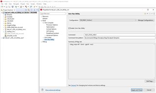
if(sciaGetWordDataCM_Avi() != 0x08AA)
{
while(1)
{
// Stay inside since error!!!
}
}
readReservedFn_Avi(); //reads and discards 8 reserved words
EntryAddrCMKernel_Avi = getLongData_Avi();
uint32_t byte4 = EntryAddrCMKernel_Avi & 0xFF000000;
uint32_t byte3 = EntryAddrCMKernel_Avi & 0x00FF0000;
uint32_t byte2 = EntryAddrCMKernel_Avi & 0x0000FF00;
uint32_t byte1 = EntryAddrCMKernel_Avi & 0x000000FF;
byte4 = byte4 >> 8;
byte3 = byte3 << 8;
byte2 = byte2 >> 8;
byte1 = byte1 << 8;
EntryAddrCMKernel_Avi = byte3 | byte4 | byte1 | byte2;
copyDataToCPU1ToCMMSGRAM_Avi();
uint16_t x = 0;
for(x = 0; x < 32676; x++){}
for(x = 0; x < 32676; x++){}
}
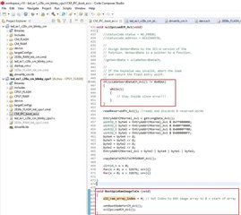
void BootGpioRamImageToCm (void)
{
u32_ram_array_index = 0; // Set Index to RAM image array to 0 = start of array
setBootModeForCM_Avi();
sciIpcLoadCM_Avi();
}
That code is basically just a copy of the flash kernel example project with slightly modified function names. I just want to avoid the process of sending data over UART (therefore the array), since I simply want to check if I can boot the CM by CPU1 with a blinking LED CM example. The function I want to call out of the CPU1 main function is called 'BootGpioRamImageToCm'.
But unfortunately there is already an endian problem right at the beginning, since the first word of the array isn't 0x08AA' but if I call for the first time 'sciaGetWordDataCM_Avi', then I receive 0xAA08. Here is the code where I enter an endless while loop:
I see that there is a difference in the first word between the file generated by the C2000 hex utility and the arm hex utility.
Question 1:
Can you please tell me if my approach is basically OK, that I add a CM RAM application to the CPU1 (FLASH configuration) application via an array? Did I miss anything regarding the endian settings calling the arm hex utility, since I set it up according to the app note chapter '3 ROM bootloader'?
Afterwards I decided to play a bit with the 'serial_flash_programmer.exe' utility. I created a new blinking LED example project for CPU1 and CM in build configuration FLASH:
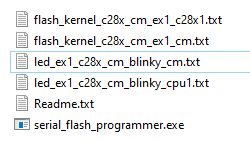
The 'kernel' projects are compiled of course in build configuration RAM but the blinking LED examples in build configuration FLASH. I called the following command:
serial_flash_programmer.exe -d f2838x -k flash_kernel_c28x_cm_ex1_c28x1.txt -a led_ex1_c28x_cm_blinky_cpu1.txt -o flash_kernel_c28x_cm_ex1_cm.txt -r led_ex1_c28x_cm_blinky_cm.txt -b 9600 -p COM5 -v
After a few minutes the CPU1 flash kernel was sent and called:
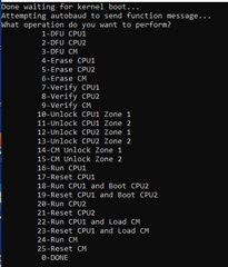
I entered first option 1 and my flle 'led_ex1_c28x_cm_blinky_cpu1.txt' was written to the flash (when I change the boot-mode pins to flash-boot and power cycle, I see that CPU1 is toggeling the LED 1).
Afterwards I called the tool again (boot-mode pins set to UART) and used afterwards option 1 - DFU CPU1. But when I then use option 22, I am expecting that the CM flash kernel and afterwards the application 'led_ex1_c28x_cm_blinky_cm.txt' is downloaded, but for some reason the tool asks me for an entry point address:
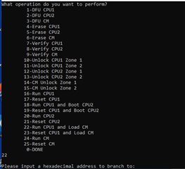
Question 2:
I don't understand why I have to enter any entry point address, since the entry points are already placed inside the *.txt files (the files that holds the application in boot-table format). Which address is expeced to be entered here, the entry point from the CM flash kernel or the CM application? And do I need to enter that address with a preceeding 0x or just the hex value?
Thanks,
Inno
Hello,
If I understand correctly, you are trying to copy over the CM LED example via IPC to the CM core? I am not sure what is causing the endianness to be switched, I would recommend stepping through the flash kernel projects, specifically into the getWordData function you are referring to, in C2000Ware first to understand the functionality correctly. You can load the projects in CCS, refer to section 5.2.4 of the app note. Once the project is loaded, you can set breakpoints to see the functionality of the getWordData function.
For the second question, the entry point of the CPU1 application is being asked. Option 22 hands over control from the CPU1 kernel to the CM kernel, but first the CPU1 kernel needs an entry point to jump to for the CPU1 application - this entry point is given at the end of the DFU CPU1 option. You should have the 0x preceding the address when typing it in.
Thanks
Anu
Hello Anu,
You are correct, I am trying to copy over a ‘CM LED example in build configuration RAM’ via IPC to the CM core and let it run right away. That ‘CM LED example in build configuration RAM’ example was converted to an C code array and added to a ‘CPU1 LED example in build configuration FLASH’, so I can leave out the UART data transfer. I just want to focus on booting the CM.
I made some progress about the get getWordData function, which is in my code above called ‘sciaGetWordDataCM_Avi’. The function is absolutely correct and does the right thing. There is just one minor issue in my code when reading the ‘key value’ (first 16 bits of the array), which I believe is compensated by the C++ flash programmer tool. Please look inside chapter ‘ARM Assembly Language Tools’ ‘spnu118y.pdf’. The key value inside the txt file is either 0x10 0xAA (for 16 bit GPIO) or 0x08 0xAA (for 16 bit GPIO).
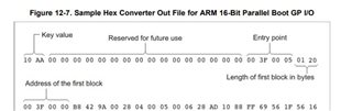
If you now look how the flash kernel example ‘getWordData’ function (more specifically ‘sciaGetWordDataCM’) works, you will see that the first byte received over UART is stored inside the lower byte and the second received byte over UART is stored in the upper byte:
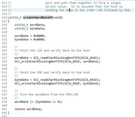
So if the C++ flash programmer tool would send the CM file byte by byte, then the key value will be 0xAA08 and not 0x08AA.
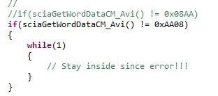
That means that I slightly modified my code to pass this check:
I checked all the other values, which I read from my C-code array via sciaGetWordDataCM_Avi / getLongData_Avi., like entry point address, address where to store the data, length/number of bytes information, everything else is correct.
I now have a remaining problem, which is that I don’t get any IPC acknowledge from the CM. The program waits endless for an acknowledge of the CM inside ‘IPC_waitForFlag’ from the CM:
I know it is a big favor I am asking for, but I am running out of ideas. Would it be possible to you to reproduce what I did on a ‘TMDSCNCD28388D’ evaluation board? I believe it can be done very fast.
1) Import the project:
C:\ti\c2000\C2000Ware_4_00_00_00\driverlib\f2838x\examples\c28x_cm\led
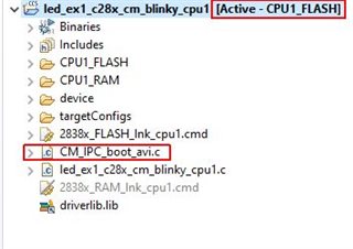
2) Add a new C-file to the CPU1 blinking LED example (in my case ‘CM_IPC_boot_avi.c’) and copy the below embedded code inside the file (in build configuration FLASH):
#include "device.h"

uint8_t Boot_IMG[]=
{
0x08, 0xAA, 0x00, 0x00, 0x00, 0x00, 0x00, 0x00, 0x00, 0x00, 0x00, 0x00, 0x00, 0x00, 0x00, 0x00, 0x00, 0x00, 0x20, 0x00, 0x0B, 0x09, 0x00, 0x06,
0x20, 0x00, 0x08, 0x00, 0x00, 0xF0, 0x82, 0xB9, 0x70, 0x47,
0x01, 0x40, 0x20, 0x00, 0x0C, 0x00, 0x00, 0xC2, 0xFF, 0x1F, 0x01, 0x08, 0x00, 0x20, 0xA9, 0x0B, 0x00, 0x20, 0x47, 0x0B, 0x00, 0x20, 0x17, 0x0A,
0x00, 0x20, 0x17, 0x0A, 0x00, 0x20, 0x17, 0x0A, 0x00, 0x20, 0x00, 0x00, 0x00, 0x00, 0x00, 0x00, 0x00, 0x00, 0x00, 0x00, 0x00, 0x00, 0x00, 0x00,
0x00, 0x00, 0x17, 0x0A, 0x00, 0x20, 0x17, 0x0A, 0x00, 0x20, 0x00, 0x00, 0x00, 0x00, 0x17, 0x0A, 0x00, 0x20, 0x17, 0x0A, 0x00, 0x20, 0x17, 0x0A,
0x00, 0x20, 0x17, 0x0A, 0x00, 0x20, 0x17, 0x0A, 0x00, 0x20, 0x17, 0x0A, 0x00, 0x20, 0x17, 0x0A, 0x00, 0x20, 0x17, 0x0A, 0x00, 0x20, 0x17, 0x0A,
0x00, 0x20, 0x17, 0x0A, 0x00, 0x20, 0x17, 0x0A, 0x00, 0x20, 0x17, 0x0A, 0x00, 0x20, 0x17, 0x0A, 0x00, 0x20, 0x17, 0x0A, 0x00, 0x20, 0x17, 0x0A,
0x00, 0x20, 0x17, 0x0A, 0x00, 0x20, 0x17, 0x0A, 0x00, 0x20, 0x17, 0x0A, 0x00, 0x20, 0x17, 0x0A, 0x00, 0x20, 0x17, 0x0A, 0x00, 0x20, 0x17, 0x0A,
0x00, 0x20, 0x17, 0x0A, 0x00, 0x20, 0x17, 0x0A, 0x00, 0x20, 0x17, 0x0A, 0x00, 0x20, 0x17, 0x0A, 0x00, 0x20, 0x17, 0x0A, 0x00, 0x20, 0x17, 0x0A,
0x00, 0x20, 0x17, 0x0A, 0x00, 0x20, 0x17, 0x0A, 0x00, 0x20, 0x17, 0x0A, 0x00, 0x20, 0x17, 0x0A, 0x00, 0x20, 0x17, 0x0A, 0x00, 0x20, 0x17, 0x0A,
0x00, 0x20, 0x17, 0x0A, 0x00, 0x20, 0x17, 0x0A, 0x00, 0x20, 0x17, 0x0A, 0x00, 0x20, 0x17, 0x0A, 0x00, 0x20, 0x17, 0x0A, 0x00, 0x20, 0x17, 0x0A,
0x00, 0x20, 0x17, 0x0A, 0x00, 0x20, 0x17, 0x0A, 0x00, 0x20, 0x17, 0x0A, 0x00, 0x20, 0x17, 0x0A, 0x00, 0x20, 0x17, 0x0A, 0x00, 0x20, 0x17, 0x0A,
0x00, 0x20, 0x17, 0x0A, 0x00, 0x20, 0x17, 0x0A, 0x00, 0x20, 0x17, 0x0A, 0x00, 0x20, 0x17, 0x0A, 0x00, 0x20, 0x17, 0x0A, 0x00, 0x20, 0x17, 0x0A,
0x00, 0x20, 0x17, 0x0A, 0x00, 0x20, 0x17, 0x0A, 0x00, 0x20, 0x17, 0x0A, 0x00, 0x20, 0x17, 0x0A, 0x00, 0x20, 0x17, 0x0A, 0x00, 0x20, 0x17, 0x0A,
0x00, 0x20, 0x17, 0x0A, 0x00, 0x20, 0x17, 0x0A, 0x00, 0x20, 0x17, 0x0A, 0x00, 0x20, 0x17, 0x0A, 0x00, 0x20, 0x17, 0x0A, 0x00, 0x20, 0x17, 0x0A,
0x00, 0x20, 0x17, 0x0A, 0x00, 0x20, 0x17, 0x0A, 0x00, 0x20, 0x17, 0x0A, 0x00, 0x20,
0x00, 0x06, 0x1F, 0xFF, 0xE0, 0x00, 0x40, 0x1E, 0xFD, 0xD1, 0x70, 0x47,
0x00, 0x18, 0x1F, 0xFF, 0xE0, 0x08, 0xAF, 0x09, 0x00, 0x20, 0x93, 0x0B, 0x00, 0x20, 0x00, 0x01, 0x00, 0x00, 0x00, 0xFF, 0xF0, 0x00, 0x10, 0xE0,
0xFF, 0x1F, 0x00, 0xC0, 0x00, 0x20,
0x03, 0xA2, 0x20, 0x00, 0x08, 0x08, 0x00, 0x2A, 0x4A, 0xD0, 0x5F, 0xEA, 0x00, 0x0C, 0x8B, 0x07, 0x1C, 0xD1, 0x83, 0x07, 0x22, 0xD1, 0x10, 0x2A,
0x08, 0xD3, 0x70, 0xB4, 0x10, 0x3A, 0x78, 0xC9, 0x78, 0xC0, 0x10, 0x3A, 0xFB, 0xD2, 0x70, 0xBC, 0x10, 0x32, 0x38, 0xD0, 0x04, 0x2A, 0x2C, 0xD3,
0x08, 0x2A, 0x05, 0xD3, 0x0C, 0x2A, 0x24, 0xBF, 0x08, 0xC9, 0x08, 0xC0, 0x08, 0xC9, 0x08, 0xC0, 0x08, 0xC9, 0x08, 0xC0, 0x92, 0x07, 0x2A, 0xD0,
0x92, 0x0F, 0x22, 0xE0, 0x0B, 0x78, 0x03, 0x70, 0x49, 0x1C, 0x40, 0x1C, 0x52, 0x1E, 0x22, 0xD0, 0x8B, 0x07, 0xF7, 0xD1, 0xC3, 0x07, 0x14, 0xD1,
0x83, 0x07, 0xD8, 0xD0, 0x12, 0x1F, 0x12, 0xD3, 0x08, 0xC9, 0x03, 0x80, 0x1B, 0x0C, 0x43, 0x80, 0x00, 0x1D, 0x12, 0x1F, 0xF8, 0xD2, 0x0A, 0xE0,
0x08, 0xC9, 0x03, 0x70, 0x1B, 0x0A, 0x43, 0x70, 0x1B, 0x0A, 0x83, 0x70, 0x1B, 0x0A, 0xC3, 0x70, 0x00, 0x1D, 0x12, 0x1F, 0xF4, 0xD2, 0x12, 0x1D,
0x05, 0xD0, 0x0B, 0x78, 0x03, 0x70, 0x49, 0x1C, 0x40, 0x1C, 0x52, 0x1E, 0xF9, 0xD1, 0x60, 0x46, 0x70, 0x47, 0x00, 0xB5, 0xAD, 0xF1, 0x14, 0x0D,
0x01, 0x91, 0x00, 0x90, 0x00, 0x98, 0x00, 0xF0, 0x3C, 0xF9, 0x18, 0xB9, 0x0D, 0xA0, 0xE9, 0x21, 0x00, 0xF0, 0x63, 0xF9, 0x00, 0x99, 0x1C, 0x48,
0x49, 0x09, 0x00, 0xEB, 0x01, 0x10, 0x02, 0x90, 0x00, 0x98, 0x01, 0x21, 0x00, 0xF0, 0x1F, 0x00, 0x81, 0x40, 0x03, 0x91, 0x01, 0x98, 0x18, 0xB9,
0x03, 0x98, 0x02, 0x99, 0x88, 0x60, 0x02, 0xE0, 0x03, 0x98, 0x02, 0x99, 0x48, 0x60, 0x05, 0xB0, 0x00, 0xBD, 0x43, 0x3A, 0x2F, 0x74, 0x69, 0x2F,
0x63, 0x32, 0x30, 0x30, 0x30, 0x2F, 0x43, 0x32, 0x30, 0x30, 0x30, 0x57, 0x61, 0x72, 0x65, 0x5F, 0x33, 0x5F, 0x30, 0x34, 0x5F, 0x30, 0x30, 0x5F,
0x30, 0x30, 0x2F, 0x64, 0x72, 0x69, 0x76, 0x65, 0x72, 0x6C, 0x69, 0x62, 0x2F, 0x66, 0x32, 0x38, 0x33, 0x38, 0x78, 0x2F, 0x64, 0x72, 0x69, 0x76,
0x65, 0x72, 0x6C, 0x69, 0x62, 0x5F, 0x63, 0x6D, 0x2F, 0x67, 0x70, 0x69, 0x6F, 0x2E, 0x68, 0x00, 0xC0, 0x46, 0x00, 0x30, 0x08, 0x40, 0x08, 0xB5,
0x00, 0x20, 0x00, 0xF0, 0x9E, 0xF8, 0x4F, 0xF4, 0x80, 0x60, 0x00, 0xF0, 0x9A, 0xF8, 0x4F, 0xF4, 0x00, 0x60, 0x00, 0xF0, 0x96, 0xF8, 0x4F, 0xF4,
0x40, 0x60, 0x00, 0xF0, 0x92, 0xF8, 0x01, 0x20, 0x00, 0xF0, 0x8F, 0xF8, 0x40, 0xF2, 0x01, 0x20, 0x00, 0xF0, 0x8B, 0xF8, 0x40, 0xF2, 0x01, 0x40,
0x00, 0xF0, 0x87, 0xF8, 0x40, 0xF2, 0x01, 0x50, 0x00, 0xF0, 0x83, 0xF8, 0x40, 0xF6, 0x01, 0x00, 0x00, 0xF0, 0x7F, 0xF8, 0x02, 0x20, 0x00, 0xF0,
0x7C, 0xF8, 0x4F, 0xF4, 0x81, 0x70, 0x00, 0xF0, 0x78, 0xF8, 0x40, 0xF2, 0x02, 0x20, 0x00, 0xF0, 0x74, 0xF8, 0x40, 0xF2, 0x02, 0x40, 0x00, 0xF0,
0x70, 0xF8, 0x40, 0xF2, 0x02, 0x60, 0x00, 0xF0, 0x6C, 0xF8, 0x40, 0xF6, 0x02, 0x00, 0x00, 0xF0, 0x68, 0xF8, 0x08, 0xBD, 0xF8, 0xB5, 0x84, 0x46,
0x40, 0xF6, 0xFF, 0x74, 0x1C, 0xF8, 0x01, 0x3B, 0x00, 0x22, 0x10, 0xE0, 0x48, 0x1B, 0x40, 0x1E, 0x10, 0xF8, 0x01, 0x5B, 0x7F, 0x1E, 0x01, 0xF8,
0x01, 0x5B, 0xF9, 0xD1, 0x03, 0xE0, 0x1C, 0xF8, 0x01, 0x0B, 0x01, 0xF8, 0x01, 0x0B, 0x52, 0x1C, 0x5B, 0x08, 0x08, 0x2A, 0xEA, 0xDA, 0x58, 0x08,
0xF5, 0xD2, 0x1C, 0xF8, 0x01, 0x0B, 0x1C, 0xF8, 0x01, 0x5B, 0x05, 0xF0, 0x0F, 0x07, 0xFF, 0x1C, 0xC5, 0xF3, 0x03, 0x15, 0x12, 0x2F, 0x45, 0xEA,
0x00, 0x15, 0x08, 0xD1, 0x1C, 0xF8, 0x01, 0x6B, 0x30, 0x0A, 0x24, 0xBF, 0x1C, 0xF8, 0x01, 0x0B, 0x60, 0xF3, 0xDF, 0x16, 0xBF, 0x19, 0xAC, 0x42,
0xD4, 0xD1, 0xF8, 0xBD, 0xFE, 0xE7, 0x08, 0xB5, 0x00, 0xF0, 0x95, 0xF8, 0x22, 0x20, 0x00, 0x21, 0xFF, 0xF7, 0x3F, 0xFF, 0x12, 0x48, 0x00, 0x68,
0x08, 0x28, 0x03, 0xDA, 0x11, 0x48, 0xFD, 0xF7, 0xE6, 0xFA, 0x02, 0xE0, 0x10, 0x48, 0xFD, 0xF7, 0xE2, 0xFA, 0x22, 0x20, 0x01, 0x21, 0xFF, 0xF7,
0x30, 0xFF, 0x0A, 0x48, 0x00, 0x68, 0x08, 0x28, 0x03, 0xDA, 0x09, 0x48, 0xFD, 0xF7, 0xD7, 0xFA, 0x02, 0xE0, 0x08, 0x48, 0xFD, 0xF7, 0xD3, 0xFA,
0x05, 0x49, 0x08, 0x68, 0x40, 0x1C, 0x08, 0x60, 0x03, 0x48, 0x02, 0x49, 0x00, 0x68, 0x00, 0xF0, 0x0F, 0x00, 0x08, 0x60, 0xD6, 0xE7, 0x00, 0xC0,
0x00, 0x20, 0x32, 0xE4, 0x3D, 0x01, 0x67, 0xC8, 0x7B, 0x02, 0x1C, 0xB5, 0xAD, 0xF8, 0x00, 0x00, 0xBD, 0xF8, 0x00, 0x00, 0x00, 0xF0, 0x1F, 0x00,
0x80, 0x00, 0xAD, 0xF8, 0x02, 0x00, 0xBD, 0xF8, 0x00, 0x00, 0x00, 0xF4, 0xF8, 0x50, 0x00, 0x0A, 0xAD, 0xF8, 0x04, 0x00, 0x07, 0x49, 0x07, 0x4A,
0xBD, 0xF8, 0x02, 0x00, 0xBD, 0xF8, 0x04, 0x40, 0x40, 0x18, 0x03, 0x68, 0x01, 0x21, 0xA1, 0x40, 0x19, 0x43, 0x0A, 0x43, 0x02, 0x60, 0x1C, 0xBD,
0xC0, 0x46, 0x00, 0xC0, 0x0F, 0x40, 0x00, 0x00, 0x34, 0x56, 0xB0, 0xB5, 0x0C, 0x48, 0x0C, 0x4D, 0xA8, 0x42, 0x10, 0xD0, 0x0C, 0x48, 0x0C, 0x4C,
0xA0, 0x42, 0x0C, 0xD0, 0x00, 0x1B, 0x08, 0x3C, 0xC7, 0x10, 0x54, 0xF8, 0x08, 0x0F, 0x01, 0x78, 0x55, 0xF8, 0x21, 0x20, 0x61, 0x68, 0x40, 0x1C,
0x90, 0x47, 0x7F, 0x1E, 0xF5, 0xD1, 0x00, 0xBF, 0x00, 0xBF, 0xB0, 0xBD, 0xC0, 0x46, 0x10, 0xE0, 0xFF, 0x1F, 0x08, 0xE0, 0xFF, 0x1F, 0x20, 0xE0,
0xFF, 0x1F, 0x18, 0xE0, 0xFF, 0x1F, 0x07, 0x48, 0x80, 0xF3, 0x08, 0x88, 0x00, 0xBF, 0x00, 0xBF, 0x00, 0xF0, 0x45, 0xF8, 0x08, 0xB1, 0xFF, 0xF7,
0xD4, 0xFF, 0x00, 0x20, 0xFF, 0xF7, 0x7B, 0xFF, 0x01, 0x20, 0x00, 0xF0, 0x3E, 0xF8, 0x00, 0xC2, 0xFF, 0x1F, 0xAD, 0xF1, 0x08, 0x0D, 0x00, 0x90,
0x00, 0x9A, 0x00, 0x21, 0x00, 0x20, 0xA8, 0x2A, 0x00, 0xD8, 0x01, 0x21, 0x01, 0xB1, 0x01, 0x20, 0x02, 0xB0, 0x70, 0x47, 0xFE, 0xE7, 0x08, 0xB5,
0x00, 0xF0, 0x13, 0xF8, 0xFF, 0xF7, 0xF3, 0xFE, 0x02, 0x48, 0x00, 0xF0, 0x04, 0xF8, 0x08, 0xBD, 0xC0, 0x46, 0x00, 0x0C, 0x00, 0x20, 0xAD, 0xF1,
0x08, 0x0D, 0x00, 0x90, 0x02, 0x49, 0x00, 0x98, 0x08, 0x60, 0x02, 0xB0, 0x70, 0x47, 0x08, 0xED, 0x00, 0xE0, 0x02, 0x49, 0x08, 0x88, 0x40, 0xF0,
0x68, 0x00, 0x08, 0x80, 0x70, 0x47, 0x0C, 0x00, 0x08, 0x40, 0xAD, 0xF1, 0x08, 0x0D, 0x01, 0x91, 0x00, 0x90, 0x00, 0xBE, 0x02, 0xB0, 0x70, 0x47,
0xD0, 0xF8, 0x03, 0x20, 0xC3, 0x1D, 0x08, 0x46, 0x19, 0x46, 0xFF, 0xF7, 0x34, 0xBE, 0x01, 0x20, 0x70, 0x47, 0x00, 0xBF, 0xFE, 0xE7, 0xFE, 0xE7,
0x00, 0x00
};


uint32_t u32_ram_array_index = 0;
uint32_t EntryAddrCMKernel_Avi;
#define KERNEL_BUFFER_SIZE_AVI 250 // Must be the same as '#define KERNEL_BUFFER_SIZE 250' inside file 'flash_kernel_c28x_cm_ex1_sci_boot_cpu1.c'

#pragma DATA_SECTION(kernelBuffer, "MSGRAM_CPU_TO_CM")
uint16_t kernelBuffer[KERNEL_BUFFER_SIZE_AVI];
//extern uint16_t kernelBuffer[KERNEL_BUFFER_SIZE_AVI];

//
// This function sets the boot mode for CM
//
void setBootModeForCM_Avi(void){

   Flash_releasePumpSemaphore();

   //Clear all flags
   IPC_clearFlagLtoR(IPC_CPU1_L_CM_R, IPC_FLAG_ALL);

   //set boot mode
   Device_bootCM(BOOTMODE_IPC_MSGRAM_COPY_LENGTH_200W | BOOTMODE_IPC_MSGRAM_COPY_BOOT_TO_S0RAM);
}

uint16_t sciaGetByteDataCM_Avi(void)
{
   uint8_t byteData;
   byteData = 0x00;

   //
   // Fetch the MSB and verify back to the host
   //
   byteData = Boot_IMG[u32_ram_array_index];
   u32_ram_array_index++;

   return byteData;
}

uint16_t sciaGetWordDataCM_Avi(void)
{
    uint16_t wordData;
    uint16_t byteData;

    wordData = 0x0000;
    byteData = 0x0000;

    //
    // Fetch the LSB and verify back to the host
    //
    wordData = Boot_IMG[u32_ram_array_index];
    u32_ram_array_index++;

    //
    // Fetch the MSB and verify back to the host
    //
    byteData = Boot_IMG[u32_ram_array_index];
    u32_ram_array_index++;

    //
    // form the wordData from the MSB:LSB
    //
    wordData |= (byteData << 8);

    return wordData;
}

uint32_t getLongData_Avi()
{
    uint32_t longData;

    //
    // Fetch the upper 1/2 of the 32-bit value
    //
    longData = ( (uint32_t)sciaGetWordDataCM_Avi() << 16);

    //
    // Fetch the lower 1/2 of the 32-bit value
    //
    longData |= (uint32_t)sciaGetWordDataCM_Avi();

    return(longData);
}


//
// readReservedFn - This function reads 8 reserved words in the header.
//                   None of these reserved words are used by the
//                   this boot loader at this time, they may be used in
//                   future devices for enhancements.  Loaders that use
//                   these words use their own read function.
//
void readReservedFn_Avi()
{
    uint16_t i;

    //
    // Read and discard the 8 reserved words.
    //
    for(i = 1; i <= 8; i++)
    {
        sciaGetWordDataCM_Avi();
    }
    return;
}


void clearKernelBuffer_Avi(void){
    uint16_t index = 0;
    for (index = 0; index < KERNEL_BUFFER_SIZE_AVI; index++){
        kernelBuffer[index] = 0x0000;
    }

}

//
// CopyDataToCPU1ToCMMSGRAM
// This function takes the CM kernel being streamed through SCI and places it
// in a buffer in CPU1TOCMMSGRAM where it can be accessed by CM to then copy
// into CM RAM. CPU1 and CM first synchronize with each other and then CPU1
// starts sending the kernel to CM. Once it hasfilled up the buffer, it signals
// CM. It then waits on CM to signal that it has finished copying the contents
// of the buffer before filling it up again with the next section of the
// kernel. CPU1 continues this operation until a blocksize of 00 00 is
// encountered, at which point it lets CM know that it has finished
// transmitting the kernel and waits for an acknowledgement from CM before
// exiting the function.
//
void copyDataToCPU1ToCMMSGRAM_Avi(void)
{
    IPC_sync(IPC_CPU1_L_CM_R, IPC_FLAG1);

    struct HEADER {
        uint32_t DestAddr;
        uint16_t BlockSize;
    } BlockHeader;

    uint16_t i;
    uint16_t j;
    uint32_t byte4;
    uint32_t byte3;
    uint32_t byte2;
    uint32_t byte1;
    uint16_t bufferIndex = 0;
    uint16_t wordData = 0;

    //
    // Get the size in words of the first block
    //
    BlockHeader.BlockSize = sciaGetWordDataCM_Avi();
    byte2 = BlockHeader.BlockSize & 0x0000FF00;
    byte1 = BlockHeader.BlockSize & 0x000000FF;
    byte2 = byte2 >> 8;
    byte1 = byte1 << 8;
    BlockHeader.BlockSize = byte1 | byte2;

    //
    // While the block size is > 0 copy the data
    // to the DestAddr.  There is no error checking
    // as it is assumed the DestAddr is a valid
    // memory location
    //

    while(BlockHeader.BlockSize != (uint16_t)0x0000U)
    {
       BlockHeader.DestAddr = getLongData_Avi();
       byte4 = BlockHeader.DestAddr & 0xFF000000;
       byte3 = BlockHeader.DestAddr & 0x00FF0000;
       byte2 = BlockHeader.DestAddr & 0x0000FF00;
       byte1 = BlockHeader.DestAddr & 0x000000FF;
       byte4 = byte4 >> 8;
       byte3 = byte3 << 8;
       byte2 = byte2 >> 8;
       byte1 = byte1 << 8;
       BlockHeader.DestAddr = byte3 | byte4 | byte1 | byte2;
       for(i = 0; i < BlockHeader.BlockSize; i += 0)
       {
           //
           // The size of the block is less than the buffer size, so the entire
           // block is written to the buffer and sent to CM
           // For example. block size is 4 and buffer size is 5, so all 4 bytes
           // are sent to CM via the buffer
           //

           //
           // BlockSize is in bytes, KERNEL_BUFFER_SIZE is in words
           //
           if(BlockHeader.BlockSize < (KERNEL_BUFFER_SIZE_AVI << 1))
           {
               //
               // fill up the buffer with the SCI data stream
               //
               for(j = 0; j < BlockHeader.BlockSize; j += 0)
               {
                   byte1 = sciaGetByteDataCM_Avi();
                   j++;

                   //
                   //when there are an odd number of bytes, we don't want to
                   //get an extra byte from the data stream, so pad with 0xFF
                   //
                   if(j == BlockHeader.BlockSize)
                   {
                       byte2 = 0xFF;
                   }
                   else
                   {
                       byte2 = sciaGetByteDataCM_Avi();
                       j++;
                   }

                   wordData = (byte2 << 8) | byte1;
                   kernelBuffer[bufferIndex] = wordData;
                   bufferIndex++;
               }
               i += j;

               IPC_sendCommand(IPC_CPU1_L_CM_R, IPC_FLAG2,
                               IPC_ADDR_CORRECTION_ENABLE,
                               BlockHeader.DestAddr,
                               (uint32_t)kernelBuffer, j);
               //
               //set flag l to r
               //
               IPC_setFlagLtoR(IPC_CPU1_L_CM_R, IPC_FLAG2);

               bufferIndex = 0;

               //
               //wait for ack
               //
               IPC_waitForAck(IPC_CPU1_L_CM_R, IPC_FLAG2);
               clearKernelBuffer_Avi();

           }

           //
           // The size of the block is greater than the buffer, so it will be
           // split up and sent in chunks until the entire block is sent
           // For example, block size is 7 and buffer size is 5, so first 5
           // bytes will be sent over and then the remaining 2 bytes will be
           // sent over
           //
           else //BlockHeader.BlockSize >= BUFFER_SIZE
           {
               //
               // keep sending until we have sent over the entire block
               //
               while(i < BlockHeader.BlockSize){
                   if((BlockHeader.BlockSize - i) < (KERNEL_BUFFER_SIZE_AVI << 1))
                   {
                       for(j = 0; j < BlockHeader.BlockSize - i; j += 0)
                       {
                          byte1 = sciaGetByteDataCM_Avi();
                          j++;

                          //
                          //when there are an odd number of bytes, we don't
                          //want to get an extra byte from the data stream,
                          //so pad with 0xFF
                          //
                          if(j == BlockHeader.BlockSize)
                          {
                              byte2 = 0xFF;
                          }
                          else
                          {
                              byte2 = sciaGetByteDataCM_Avi();
                              j++;
                          }
                          wordData = (byte2 << 8) | byte1;
                          kernelBuffer[bufferIndex] = wordData;
                          bufferIndex++;
                       }
                       //
                       // increment i outside here so it doesn't affect loop
                       // above
                       //
                       i += j;

                       IPC_sendCommand(IPC_CPU1_L_CM_R, IPC_FLAG2,
                                       IPC_ADDR_CORRECTION_ENABLE,
                                       BlockHeader.DestAddr,
                                       (uint32_t)kernelBuffer, j);
                       //
                       //set flag l to r
                       //
                       IPC_setFlagLtoR(IPC_CPU1_L_CM_R, IPC_FLAG2);

                       bufferIndex = 0;

                       //
                       //wait for ack
                       //
                       IPC_waitForAck(IPC_CPU1_L_CM_R, IPC_FLAG2);
                       clearKernelBuffer_Avi();
                   }
                   else
                   {
                       for(j = 0; j < (KERNEL_BUFFER_SIZE_AVI << 1); j += 2)
                       {
                           wordData = sciaGetWordDataCM_Avi();
                           kernelBuffer[bufferIndex] = wordData;
                           bufferIndex++;
                       }
                       i += j;
                       IPC_sendCommand(IPC_CPU1_L_CM_R, IPC_FLAG2,
                                       IPC_ADDR_CORRECTION_ENABLE,
                                       BlockHeader.DestAddr,
                                       (uint32_t)kernelBuffer, j);
                       //
                       //to account for byte addressing in CM
                       //
                       BlockHeader.DestAddr += j;

                       //
                       //set flag l to r
                       //
                       IPC_setFlagLtoR(IPC_CPU1_L_CM_R, IPC_FLAG2);

                       bufferIndex = 0;

                       //
                       //wait for ack
                       //
                       IPC_waitForAck(IPC_CPU1_L_CM_R, IPC_FLAG2);
                       clearKernelBuffer_Avi();
                   }
               }
           }
       }
       //
       // Get the size of the next block
       //
       BlockHeader.BlockSize = sciaGetWordDataCM_Avi();
       byte2 = BlockHeader.BlockSize & 0x0000FF00;
       byte1 = BlockHeader.BlockSize & 0x000000FF;
       byte2 = byte2 >> 8;
       byte1 = byte1 << 8;
       BlockHeader.BlockSize = byte1 | byte2;
    }
    //BlockSize is 0, CM will exit out of the loop
    IPC_sendCommand(IPC_CPU1_L_CM_R, IPC_FLAG2, IPC_ADDR_CORRECTION_ENABLE,
                    EntryAddrCMKernel_Avi, (uint32_t)kernelBuffer, 0);
    IPC_setFlagLtoR(IPC_CPU1_L_CM_R, IPC_FLAG3);
    IPC_waitForAck(IPC_CPU1_L_CM_R, IPC_FLAG3);

    return;
}


void sciIpcLoadCM_Avi(void)
{
    //statusCode.status = NO_ERROR;
    //statusCode.address = 0x12346578;

    //
    // Assign GetWordData to the SCI-A version of the
    // function. GetWordData is a pointer to a function.
    //
    //getWordData = sciaGetWordDataCM;

    //
    // If the KeyValue was invalid, abort the load
    // and return the flash entry point.
    //
    //if(sciaGetWordDataCM_Avi() != 0x08AA)
    if(sciaGetWordDataCM_Avi() != 0xAA08)
    {
        while(1)
        {
            // Stay inside since error!!!
        }
    }

    readReservedFn_Avi(); //reads and discards 8 reserved words

    EntryAddrCMKernel_Avi = getLongData_Avi();
    uint32_t byte4 = EntryAddrCMKernel_Avi & 0xFF000000;
    uint32_t byte3 = EntryAddrCMKernel_Avi & 0x00FF0000;
    uint32_t byte2 = EntryAddrCMKernel_Avi & 0x0000FF00;
    uint32_t byte1 = EntryAddrCMKernel_Avi & 0x000000FF;
    byte4 = byte4 >> 8;
    byte3 = byte3 << 8;
    byte2 = byte2 >> 8;
    byte1 = byte1 << 8;
    EntryAddrCMKernel_Avi = byte3 | byte4 | byte1 | byte2;

    copyDataToCPU1ToCMMSGRAM_Avi();

    uint16_t x = 0;
    for(x = 0; x < 32676; x++){}
    for(x = 0; x < 32676; x++){}

}


void BootGpioRamImageToCm (void)
{
    u32_ram_array_index = 0; // Set Index to RAM image array to 0 = start of array

    setBootModeForCM_Avi();
    sciIpcLoadCM_Avi();
}
3) Change the main function as follows:
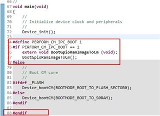
Are you able to run my code inside function 'BootGpioRamImageToCm' and boot the CM over IPC with the image inside my array?
Regards,
Inno
Hello Anu, thank you very much for your effort! I am about to write down everything what I did in the past.
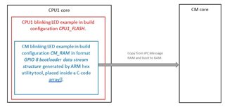
Although I am sure that you know what I am trying to achieve, I will show inside the following picture the task I would like to achieve:
One thing you can check for is if the CopyDataToCMRAM array in the CPU1 project is being properly placed in memory. Because the sync function is not fully going through, it could be that the copy function is not being placed into S0RAM during the CM Boot sequence. This copy function is needed to transfer the LED application to CM.
When you build the CPU1 project, does CCS complain that not all sections of memory can be written to? If so, you will need to modify your GEL files to allow the MSGRAM to be written to. There is a modified GEL file available in the example folder in C2000Ware. If you are not using CCS v10.1, please refer to the release notes of the C2000Ware v4.0 release for tips on how to change your GEL files to allow writing to MSGRAM.
Also, if the LED application is being placed in a C array, where are you using GetWordData? That is only used for fetching data from SCI, you don't need it if you are accessing the array for your data.
Thanks
Anu
Hello Anu,
About the first thing that you mentioned:
I did not add that array 'CopyDataToCMRAM' at all to my blinking LED application. I saw that array when I learned the flash_kernel example project, but I wasn't aware that the CM boot-loader requires an array to reside at the beginning of CPU1 -> CM messae RAM 1. What does this array do and why does the CM ROM Bootloader requires it? However, I will make the linker command file to look the same about the CPU1->CM message RAM and add the array to the blinking LED project.
About the second thing you mentioned above:
I do not get any complains from the compiler/linker. But I have to say that I impored the flash_kernel example project to a CCS environment, using C2000 ware version 03.04.00.00. This is because I am developing in parallel on an own custom board project for this CPU and unfortunately that project uses the older version of C2000 ware. I am hoping that this does not prevent me from getting the IPC boot working.
About the third comment from you:
Please look at the below code, I copied the GetWordData function to my project, renamed it into 'sciaGetWordDataCM_Avi' and changed slightliy the functionality, which means instead of reading from SCI I read the data from the array 'Boot_IMG'.
uint16_t sciaGetWordDataCM_Avi(void)
{
    uint16_t wordData;
    uint16_t byteData;

    wordData = 0x0000;
    byteData = 0x0000;

    //
    // Fetch the LSB and verify back to the host
    //
    wordData = Boot_IMG[u32_ram_array_index];
    u32_ram_array_index++;

    //
    // Fetch the MSB and verify back to the host
    //
    byteData = Boot_IMG[u32_ram_array_index];
    u32_ram_array_index++;

    //
    // form the wordData from the MSB:LSB
    //
    wordData |= (byteData << 8);

    return wordData;
}
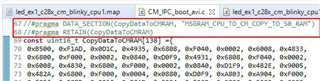
However, in the meanwhile I made some progress. Your first comment in your previous point was a very good hint. First of all I copied the array ‘CopyDataToCMRAM’ to my blinking LED project and I also changed the linker command file to match the flash_kernel example project:
The memory declaration in the map file:
CPUTOCMRAM_0 : origin = 0x039000, length = 0x000400 // avi modification
CPUTOCMRAM_1 : origin = 0x039400, length = 0x000400 // avi modification
//CPUTOCMRAM : origin = 0x039000, length = 0x000800 // avi modification
The section declaration inside the map file:
//MSGRAM_CPU_TO_CM : > CPUTOCMRAM, type=NOINIT // avi modification
MSGRAM_CPU_TO_CM > CPUTOCMRAM_0, type=NOINIT // avi modification
MSGRAM_CPU_TO_CM_COPY_TO_S0_RAM > CPUTOCMRAM_1, type=NOINIT // avi modification
So I added the array 'CopyDataToCMRAM' to the code:
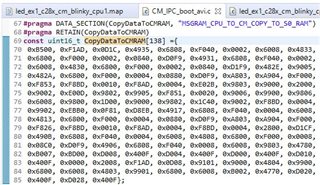
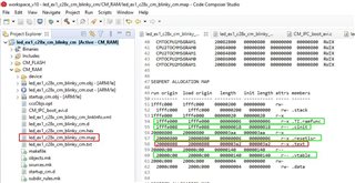
I checked the map-file to be sure, that the array is located at the correct location:
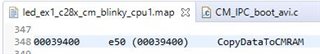
But for some reason when flashing the example, I read only 0x0000 values from the memory view window at memory address 0x39400, which is the CPU1->CM message RAM 1 and the place, where the ‘CopyDataToCMRAM’ must be located. I don't know why the debugger does not write to the CPU1->CM message RAM without giving me any notification. Even when I power cycled the board and booted from flash, it is not working.
So what I now did is the following:
Inside my main() function:
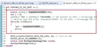
As you can see above, I am manually copying the array ‘CopyDataToCMRAM’ must be located. Only afterwards I will call the function ‘BootGpioRamImageToCm()’.
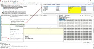
Now the program returns from the function call ‘IPC_sync(IPC_CPU1_L_CM_R, IPC_FLAG1);’ at the beginning of ‘copyDataToCPU1ToCMMSGRAM_Avi’. Even more than that, I checked the content of my CM blinking LED array called ‘Boot_IMG’ and the output sections .TI.ramfunc, .cinit, .resetisr, .vtable seem to be copied to the CM over the message RAM and I get an IPC acknowledge from the CM. See here the map file of the CM blinking LED example:
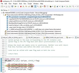
But when the code now proceeds and tries to copy the first chunk of 500 bytes (250 words) of output section .text to the message RAM and triggers an IPC Flag 2, then the program gets stuck inside 'IPC_waitForAck', see below picture:
So let me summarize:
1) In the past I did not copy the array 'CopyDataToCMRAM' to my blinking LED example.
2) Even after copying it, it seems the JTAG debugger did not write the values of that 'CopyDataToCMRAM' to CPU1->CM message RAM 1.
3) Due to item 2, I copied the array 'CopyDataToCMRAM' manually inside a for-loop to the CPU1->CM message RAM 1 before I started the IPC boot.
4) Now almost everything is working inside 'copyDataToCPU1ToCMMSGRAM_Avi'.
- The 'IPC_sync' returns now that the array 'CopyDataToCMRAM' is on the message RAM 1.
- The first 4 sections of the CM blinking LED example (e.g. .resetisr, cinit etc...) seem to be copied over IPC.
The problem is now that the first attempt copying the .text output section from my array 'Boot_IMG' over IPC to the CM is not acknowledged. Is it possible that the program code (.text section) of my CM blinking LED RAM example is located at the same memory where the 'CopyDataToCMRAM' data is located and that this 'CopyDataToCMRAM' inside the CM RAM is being overwritten by my process?
And can you please explain a bit more about the array 'CopyDataToCMRAM' and why the CM boot-loader expects it to be inside CPU1->CM message RAM 1?
Thanks,
Inno
Hello,
The CopyDataToCMRAM function was created for the CM flash kernel so that the entire kernel could be copied over from CPU1 to CM. The entirety of the kernel was too big to fit into the CPU1 to CM Message RAM, so the copy function was created so that portions could be copied over one at a time. This function is copied over from CPU1 to CM during the CM boot sequence, using the boot mode "Copy from IPC Message RAM and boot to RAM" boot mode. Once the CM core has completed its boot sequence, it goes to S0RAM, and that is where this copy function is placed. The function will take whatever the CPU1 copy function places in Message RAM and copy it over to the address the CPU1 copy function specifies. It does this until it receives a block size of 0x0000 which indicates the the end of the file.
Is it possible that the program code (.text section) of my CM blinking LED RAM example is located at the same memory where the 'CopyDataToCMRAM' data is located and that this 'CopyDataToCMRAM' inside the CM RAM is being overwritten by my process?
This is possible, you can check your CM LED example linker command file and make sure that the Copy function does not overlap with the .text sections.
Thanks
Anu
Hello Anu,
This answers my question. I compiled the CM blinking LED application in build configuration CM_RAM and ensured, that CM S0 RAM is never used. I placed all secitions in S1...S3 RAM. From now on everything is working, CPU1 boots the CM with my own application via the help of the TI 'CopyDataToCMRAM' app.
Here is a summary:
1) I previously missed adding the 'CopyDataToCMRAM' array to the blinking LED CPU1 project and ensuring that this array is located inside CPU1->CM MSGRAM 1 before trying to copy in a second step my own blinking LED CM application.
2) I also did not ensure, that the CM blinking LED application should never reside inside S0 RAM (at least it should not reside at the beginning of S0).
Now my CPU1 project rus and lets the CM toggle the 2nd LED.
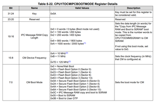
I now have one final question regarding the CM RBL (Rom Boot Loader). The TI application 'CopyDataToCMRAM' is being placed at the beginning of the CPU1->CM MSGRAM 1. But how does the CM RBL know, that he has to take the data from MSGRAM1 and not MSGRAM0 for his boot mode 'BOOTMODE_IPC_MSGRAM_COPY_BOOT_TO_S0RAM'? Is this the memory that is always used by the CM RBL for that boot-mode or does this information come from the IPC flag 1 (see here):
IPC_sync(IPC_CPU1_L_CM_R, IPC_FLAG1);
I wonder when calling the above function with argument IPC_FLAG0, if then the CM RBL looks at MSGRAM 0 for the 'CopyDataToCMRAM' instead?
Thanks,
Inno
The CM Boot sequence always reads from MSGRAM1 when using this boot mode, see below:
Thanks
Anu
Hello Anu,
Thank you very much for your support. I believe I can proceed with my tasks.
Regards,
Inno
Glad to hear, I will go ahead and close this post. If you have other questions, feel free to start a new thread.


