Part Number: TMS320F28075
Hi expert,
I have a customer meet CLA reading ADC result error.
They found this by ADC reading result abnormally, in detail, it is much higher than the sampling value. It happened at specific condition: the inverter is connected to the grid normally, and then the PV source voltage is pulled down and disconnected from the grid, it may trigger an error 427 (abnormal sampling of both AC current and voltage). The duration varies from 0.5 to 2 minutes, and then it can return to normal.
Then they draw the ADC result and CLA reading ADC result using their own GUI.
Green line is ADC result.
Red line is CLA reading result, and sometimes it is too high sometimes it is too low.

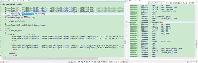
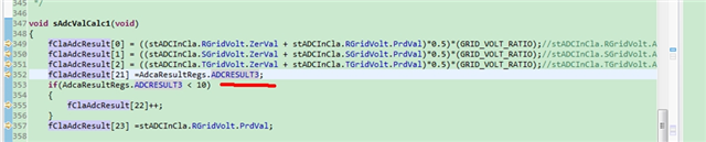
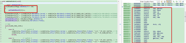
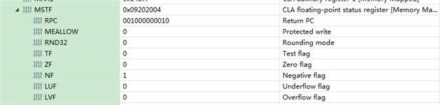
Next they check the ADC result in CLA directly and it is not right, either.

They did not give the register to a variable but just read the value and judge. The value should NOT below 800 as showed in the graph.
Next, they just checked:
HW side:
- ADC port value is correct.
- Test the crystal waveform, it is normal after the error happen.
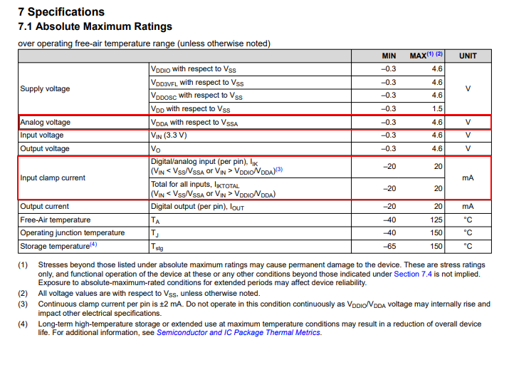
- Test the 3.3V power supply waveform, it is normal and no drop.
- Use IO toggle in the C28 interrupt and CLA interrupt to see the code running status. It works normally.
- After the error, using watchdog reset the device, and it still report the error.
SW side:
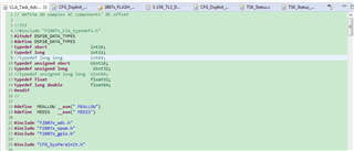
- Confirm CLA typedef information. As showed in this thread, just check whether this error. e2e.ti.com/.../c2000-cla---accessing-adc-results-register-from-within-cla-task

I just found they just put the useful CLA type define in their source file and before including other header file.
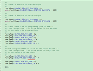
2.I have also checked the CLA configuration and CLA CMD. I did not found error.

- ADC clock is configured as 48MHz, which equals to 120M/2.5
could you kindly share your insight on potential reason for this error.
BR
Emma