This thread has been locked.

If you have a related question, please click the "Ask a related question" button in the top right corner. The newly created question will be automatically linked to this question.

TMS320F280049C: Source code problem of TIDM-02000 (PSFB PCM)

Part Number: TMS320F280049C
Other Parts Discussed in Thread: TIDM-02000, TIDM-1001

Hi Champ,

I am asking for my customer. They are studying on our reference design TIDM-02000, and wish to implement on their product.

There are some questions about the source code, may need the experts or author comment ? 

1). As I know, the published reference design content isn't implementing the burst mode.  For their real project, how do the customers implement burst mode?  Will the part be released or any example code? 

2). Can could we adjust the dead time at run time? Any example code?

3). Can we change the SR mode at run time?

4). How to get the slope compensation value (PSFB_SLOPE_INITIAL)? Any formula?

Thanks and regards,

Johnny

  • Hi Johnny,

    1). As I know, the published reference design content isn't implementing the burst mode.  For their real project, how do the customers implement burst mode?  Will the part be released or any example code? 

    No, we don't have the burst mode implemented in the TIDM-02000. For light load condition, customer could do frequency modulization (decrease the frequency) or use burst mode to maintain the system efficiency. There are probably multiple ways to implement burst mode. 1. use the slow frequency ISR to turn the PWM on/off every certain time(pre-set). 2 use similar hybrid duty mode (referring to user guide of TIDM-1001) to turn off the PWM based on the control loop output. 3. Use CLB to implement burst mode. 

    We may have some example code in 2QSDK release in LLC solution.

    2). Can could we adjust the dead time at run time? Any example code?

    This can be adjusted in the control ISR or background loop. We don't have sample code.

    3). Can we change the SR mode at run time?

    Yes, you can. 

    4). How to get the slope compensation value (PSFB_SLOPE_INITIAL)? Any formula?

    You may refer to the link below.

    e2e.ti.com/.../3548810

    Regards,

    Chen

  • Hi Chen,

    Thanks for your reply. There are few questions I would like to follow up with you, thanks.

    Mentioned in the first point "use similar hybrid duty mode".

    (1). As TIDM-1001 refers, hybrid duty mode control seems to control the "PWM switching frequency" and the "duty cycle" to regulate the output voltage, correct ?

    (2). So it is not totally equal to PWM mode(screenshot  in below) in LLC at the lowest power, correct ?

    Since the PSFB configuration may be more complicated than LLC. Is it able to change the control mode like LLC ? It looks like there will be a lot of efforts. Any comments on this ?

    Thanks and regards,

    Johnny

  • (1). As TIDM-1001 refers, hybrid duty mode control seems to control the "PWM switching frequency" and the "duty cycle" to regulate the output voltage, correct ?

    It starts with frequency control. And if the frequency reaches the pre-set limit, the frequency will be clamped and duty cycle is regulated. 

    (2). So it is not totally equal to PWM mode(screenshot  in below) in LLC at the lowest power, correct ?

    I would say it is the same. When the duty under PWM mode(hybrid duty control in TIDM-1001) equal to zero, it is kind of like a burst mode.

    Since the PSFB configuration may be more complicated than LLC. Is it able to change the control mode like LLC ? It looks like there will be a lot of efforts. Any comments on this ?

    I don't have too much information for this question since we don't have a sample code yet. But we tried to regulate the switching frequency under light load for PSFB. I think using traditional burst mode together with PCMC mode should also work fine. Efforts are needed for the transitions.

    Regards,

    Chen

  • Hi Chen,

    Thanks for your reply. It is clear to me now.

    Currently, the customer is testing the code on EVM board.

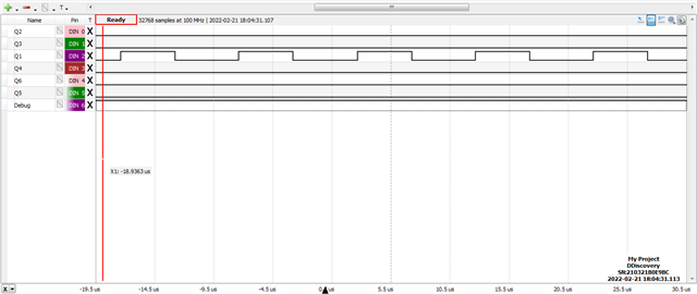
    When we try to disable all the PWM signals by calling PSFB_EnablePSFBPWM(),  it is found that it can't be disabled.

    Sometimes the different PWM signals can't be disabled at the same time on the same leg. (Q1 or Q4 signal can't be disabled at the same time)

    The waveform is showing in below.(corresponding PWM signals are connected the same as the reference design)

    Is it the same look like as your original design ? May I make sure it is the way designed?

    If so, why don't we disable all the PWM signals ? Isn't there any potential risk for doing that ?

    Thanks and regards,

    Johnny

  • Hi Johnny,

    Yes, it is the same in our original design. And we know it is not ideal though it should not impact the protection. This is due to the original configuration of PCMC together with protection. This behavior can be found in TIDM-02000 using f28004x device.

    With the new features in later devices such as f28003x, this can be resolved by changing the PCMC control implementation a little bit. 

    Regards,

    Chen

  • Dear Chen,

    I am confused.

    F28004x PWM and F28003x PWM are almost the same except the sync input/output (EPWMSYNCINSEL) and DC compare submodule latch (DCACTL/DCBCTL).

    So, you meant on F28003x, this can be resolved by DCACTL/DCBCTL which F28004x do not have?

    Wayne Huang

  • Hi Wayne,

    Yes, we need to utilize the latch features of digital compare submodule. The simple reason is that we need to change the PCMC action to use the DCAEVT1U(for example) instead of TZAU in the tripzone submodule. And latch feature is important when using DCAEVT1U. The total changes are minor.  We can sync offline if you need more detailed information on this.

    Regards,

    Chen