This thread has been locked.
If you have a related question, please click the "Ask a related question" button in the top right corner. The newly created question will be automatically linked to this question.
Hello,
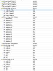
I've noticed all my CMPSSX CTRIPL flags within XbarRegs.XBARFLG1 are true when I think they should be false.
This is my code for setting up the CMPSS. I'm inverting the low comparator, I'm trying to use the CTRIPL as a check if my value falls below DACL. Am I doing that right? (Code is mostly from the Universal Motor Control Lab, no modifications to the CMPSS functions).
void HAL_setupCMPSSs(HAL_MTR_Handle handle) { HAL_MTR_Obj *obj = (HAL_MTR_Obj*) handle; #if defined(MOTOR1_ISBLDC) || defined(MOTOR1_DCLINKSS) // Refer to the Table 9-2 in Chapter 9 of TMS320F28004x // Technical Reference Manual (SPRUI33B), to configure the ePWM X-Bar #if defined(BSXL8323RS_REVA) || defined(BSXL8323RH_REVB) uint16_t cmpsaDACL = MTR1_CMPSS_DACL_VALUE; ASysCtl_selectCMPLPMux(MTR1_IDC_CMPLP_SEL, MTR1_IDC_CMPLP_MUX); // Enable CMPSS and configure the negative input signal to come from the DAC CMPSS_enableModule(obj->cmpssHandle[0]); // NEG signal from DAC for COMP-L CMPSS_configLowComparator(obj->cmpssHandle[0], CMPSS_INSRC_DAC); // Configure the output signals. Both CTRIPH/L and CTRIPOUTH/L will be fed by // the asynchronous comparator output. // Dig filter output ==> CTRIPL, Dig filter output ==> CTRIPOUTL CMPSS_configOutputsLow(obj->cmpssHandle[0], CMPSS_TRIP_FILTER | CMPSS_TRIPOUT_FILTER | CMPSS_INV_INVERTED); // Configure digital filter. For this example, the maxiumum values will be // used for the clock prescale, sample window size, and threshold. // Initialize the filter logic and start filtering CMPSS_configFilterLow(obj->cmpssHandle[0], 32, 32, 30); CMPSS_initFilterLow(obj->cmpssHandle[0]); // Set up COMPHYSCTL register // COMP hysteresis set to 2x typical value CMPSS_setHysteresis(obj->cmpssHandle[0], 1); // Use VDDA as the reference for the DAC and set DAC value to midpoint for // arbitrary reference CMPSS_configDAC(obj->cmpssHandle[0], CMPSS_DACREF_VDDA | CMPSS_DACVAL_SYSCLK | CMPSS_DACSRC_SHDW); // Set DAC-L to allowed MAX -ve current CMPSS_setDACValueLow(obj->cmpssHandle[0], cmpsaDACL); // Clear any low comparator digital filter output latch CMPSS_clearFilterLatchLow(obj->cmpssHandle[0]); #else #error This board doesn't support single shunt #endif // BSXL8323RS_REVA || BSXL8323RH_REVB #else // !(MOTOR1_ISBLDC || MOTOR1_DCLINKSS) // Refer to the Table 9-2 in Chapter 9 of TMS320F28004x // Technical Reference Manual (SPRUI33B), to configure the ePWM X-Bar uint16_t cmpsaDACH = MTR1_CMPSS_DACH_VALUE; uint16_t cmpsaDACL = MTR1_CMPSS_DACL_VALUE; uint16_t cnt; if(handle == hal.mtrHandle[MTR_1]) { ASysCtl_selectCMPHPMux(MTR1_IU_CMPHP_SEL, MTR1_IU_CMPHP_MUX); ASysCtl_selectCMPLPMux(MTR1_IU_CMPLP_SEL, MTR1_IU_CMPLP_MUX); ASysCtl_selectCMPHPMux(MTR1_IV_CMPHP_SEL, MTR1_IV_CMPHP_MUX); ASysCtl_selectCMPLPMux(MTR1_IV_CMPLP_SEL, MTR1_IV_CMPLP_MUX); // ASysCtl_selectCMPHPMux(MTR1_IW_CMPHP_SEL, MTR1_IW_CMPHP_MUX); // ASysCtl_selectCMPLPMux(MTR1_IW_CMPLP_SEL, MTR1_IW_CMPLP_MUX); } else if(handle == hal.mtrHandle[MTR_2]) { #ifdef MTR2 cmpsaDACH = MTR2_CMPSS_DACH_VALUE; cmpsaDACL = MTR2_CMPSS_DACL_VALUE; ASysCtl_selectCMPHPMux(MTR2_IU_CMPHP_SEL, MTR2_IU_CMPHP_MUX); ASysCtl_selectCMPLPMux(MTR2_IU_CMPLP_SEL, MTR2_IU_CMPLP_MUX); ASysCtl_selectCMPHPMux(MTR2_IV_CMPHP_SEL, MTR2_IV_CMPHP_MUX); ASysCtl_selectCMPLPMux(MTR2_IV_CMPLP_SEL, MTR2_IV_CMPLP_MUX); // ASysCtl_selectCMPHPMux(MTR2_IW_CMPHP_SEL, MTR2_IW_CMPHP_MUX); // ASysCtl_selectCMPLPMux(MTR2_IW_CMPLP_SEL, MTR2_IW_CMPLP_MUX); #endif } DEVICE_DELAY_US(500); for (cnt = 0; cnt < 2; cnt++) { // Set DAC-H to allowed MAX +ve current CMPSS_setDACValueHigh(obj->cmpssHandle[cnt], cmpsaDACH); // Set DAC-L to allowed MAX -ve current CMPSS_setDACValueLow(obj->cmpssHandle[cnt], cmpsaDACL); // NEG signal from DAC for COMP-H CMPSS_configHighComparator(obj->cmpssHandle[cnt], CMPSS_INSRC_DAC); // NEG signal from DAC for COMP-L CMPSS_configLowComparator(obj->cmpssHandle[cnt], CMPSS_INSRC_DAC | CMPSS_INV_INVERTED); //CMPSS_INV_INVERTED // Enable CMPSS and configure the negative input signal to come from the DAC CMPSS_enableModule(obj->cmpssHandle[cnt]); // Configure digital filter. For this example, the maxiumum values will be // used for the clock prescale, sample window size, and threshold. CMPSS_configFilterHigh(obj->cmpssHandle[cnt], 32, 32, 30); CMPSS_initFilterHigh(obj->cmpssHandle[cnt]); // Initialize the filter logic and start filtering CMPSS_configFilterLow(obj->cmpssHandle[cnt], 32, 32, 30); CMPSS_initFilterLow(obj->cmpssHandle[cnt]); // Configure the output signals. Both CTRIPH and CTRIPOUTH will be fed by // the asynchronous comparator output. // Dig filter output ==> CTRIPH, Dig filter output ==> CTRIPOUTH CMPSS_configOutputsHigh(obj->cmpssHandle[cnt], CMPSS_TRIP_FILTER); // | CMPSS_TRIPOUT_FILTER // Dig filter output ==> CTRIPL, Dig filter output ==> CTRIPOUTL CMPSS_configOutputsLow(obj->cmpssHandle[cnt], CMPSS_TRIP_FILTER); // Set up COMPHYSCTL register CMPSS_setHysteresis(obj->cmpssHandle[cnt], 2); // Use VDDA as the reference for the DAC and set DAC value to midpoint for // arbitrary reference CMPSS_configDAC(obj->cmpssHandle[cnt], CMPSS_DACREF_VDDA | CMPSS_DACVAL_SYSCLK | CMPSS_DACSRC_SHDW); // Clear any high comparator digital filter output latch CMPSS_clearFilterLatchHigh(obj->cmpssHandle[cnt]); // Clear any low comparator digital filter output latch CMPSS_clearFilterLatchLow(obj->cmpssHandle[cnt]); } #endif // !(MOTOR1_ISBLDC || MOTOR1_DCLINKSS) return; } // end of HAL_setupCMPSSs() function
These are the ADC values I believe it should be comparing with their current DACH and DACL values:
The values I'm using for configuring ADC and CMPSS:
#define MTR1_IU_ADCRESLT MTR1_IU_ADCRES_BASE + ADC_O_RESULT1 // ADCA-A11*/C0-SOC1 #define MTR1_IV_ADCRESLT MTR1_IV_ADCRES_BASE + ADC_O_RESULT1 // ADCC-A14/C4* -SOC1 #define MTR2_IU_ADCRESLT MTR2_IU_ADCRES_BASE + ADC_O_RESULT5 // ADCA-A10/C10*-SOC2 #define MTR2_IV_ADCRESLT MTR2_IV_ADCRES_BASE + ADC_O_RESULT5 // ADCC-A9*/C8 -SOC3 // CMPSS #define MTR1_IU_CMPHP_SEL ASYSCTL_CMPHPMUX_SELECT_1 // CMPSS1-A11 #define MTR1_IU_CMPLP_SEL ASYSCTL_CMPLPMUX_SELECT_1 // CMPSS1-A11, N/A #define MTR1_IV_CMPHP_SEL ASYSCTL_CMPHPMUX_SELECT_3 // CMPSS3-C4 #define MTR1_IV_CMPLP_SEL ASYSCTL_CMPLPMUX_SELECT_3 // CMPSS3-C4 #define MTR1_IU_CMPHP_MUX 1 // CMPSS1-A11 #define MTR1_IU_CMPLP_MUX 1 // CMPSS1-A11 #define MTR1_IV_CMPHP_MUX 4 // CMPSS3-C4 #define MTR1_IV_CMPLP_MUX 4 // CMPSS3-C4 #define MTR1_CMPSS_DACH_VALUE 2048+1024+512 #define MTR1_CMPSS_DACL_VALUE 2048-1024-512 #define MTR2_IU_CMPHP_SEL ASYSCTL_CMPHPMUX_SELECT_2 // CMPSS2-C10 #define MTR2_IU_CMPLP_SEL ASYSCTL_CMPLPMUX_SELECT_2 // CMPSS2-C10, N/A #define MTR2_IV_CMPHP_SEL ASYSCTL_CMPHPMUX_SELECT_4 // CMPSS4-A9 #define MTR2_IV_CMPLP_SEL ASYSCTL_CMPLPMUX_SELECT_4 // CMPSS4-A9 #define MTR2_IU_CMPHP_MUX 3 // CMPSS2-C10 #define MTR2_IU_CMPLP_MUX 3 // CMPSS2-C10 #define MTR2_IV_CMPHP_MUX 0 // CMPSS4-A9 #define MTR2_IV_CMPLP_MUX 0 // CMPSS4-A9 #define MTR2_CMPSS_DACH_VALUE 2048+1024+512 #define MTR2_CMPSS_DACL_VALUE 2048-1024-512
Thanks,
Have I interpreted the XbarRegs.XBARFLG1 correctly? I assume the CTRIP values in that register tell you if those inputs to the ePWM X-BAR have been tripped, is that right? I'm also assuming those values are equivalent to what is output by the digital filter (in my case) from the CMPSS module after inversion.
Hi Sasha,
Yes, your understanding is correct. XBARFLG1 indicates if the inputs to the ePWM X-BAR or Output X-BAR tripped. Since you have inversion enabled on COMPL and the signal on the positive input is less than DACL, the trip high status you are seeing in XBARFLG1 for COMPL makes sense. Let us know if you have more questions.
Hi Frank,
Thanks for your reply. I guess I must be misunderstanding, I thought I had setup the ADC input as the positive input for COMPL, which is greater than the DACL? So shouldn't the inverted DACL output be false?
Sasha,
Thanks for your reply. I guess I must be misunderstanding, I thought I had setup the ADC input as the positive input for COMPL, which is greater than the DACL? So shouldn't the inverted DACL output be false?
That's right. If you have inversion enabled and the positive input is greater than DACL, then output should be 0. Did you try clearing the XBARFLG1 to see if it remained set to 1? Because it could have been set to 1 during configuration when perhaps positive input was less than DACL.
I tried as you suggested to clear XBARFLG1 by manually setting the corresponding bits in XBARCLR1, and it worked. The flags went to false and stayed false, as expected. Thanks!
Is there an order of operations I should follow to configure the CMPSS to avoid false triggers? Or is manually clearing them at the end of HAL_setupCMPSSs() the only way to ensure proper function?
Is there a better way to clear them than using XBARCLR1? Does the Universal Motor Control lab code provide a function for this? I see a function called "CMPSS_clearFilterLatchLow()" but that doesn't seem to be what I need here.
I tried as you suggested to clear XBARFLG1 by manually setting the corresponding bits in XBARCLR1, and it worked. The flags went to false and stayed false, as expected. Thanks!
That's good to hear.
Is there an order of operations I should follow to configure the CMPSS to avoid false triggers? Or is manually clearing them at the end of HAL_setupCMPSSs() the only way to ensure proper function?
Usually you will want to clear all flags after all configuration code is complete and before your application code starts running.
Is there a better way to clear them than using XBARCLR1? Does the Universal Motor Control lab code provide a function for this? I see a function called "CMPSS_clearFilterLatchLow()" but that doesn't seem to be what I need here.
I think there might be some confusion here on your part. XBARFLG is only really useful for debug. Outside of that, it doesn't really have any usefulness in the application. Essentially what I mean is, you care about the CMPSS tripping the EPWM at the end of the day and not if the XBARFLG was being set. "CMPSS_clearFilterLatchLow()" function clears the COMPxSTS latch which indicates whether the latch in the CMPSS was set. Have you confirmed that the EPWM is tripping as expected from the CMPSS?
Ah ok. All my CmpssXRegs.COMPSTS are 0 so I think that's good and working. It's ironic the registers meant for debugging were causing my confusion, but I see now they're not connected to my reset code in anyway so they don't show the true state at all times. Thanks for the clarification.
My EPWM is not tripping. When testing, I can see the COMPSTS change to true as expected, but PWMs remain enabled. I can see in the EPwmXbarRegs the MUX are configured and enabled correctly. I can see in EPwmXRegs.TZFLG DCAEVT1 and DCBEVT1 become true, but pwms are still running.
I'm guessing I haven't setup motor faults correctly. I'm using Universal motor control lab code here, I noticed there wasn't a setTripZoneAction for DCXEVT1, so I added that. Am I missing something else?
EPWM_enableTripZoneSignals(obj->pwmHandle[cnt], tzOSTSet); EPWM_enableTripZoneSignals(obj->pwmHandle[cnt], EPWM_TZ_SIGNAL_CBC6); //enable DC TRIP combinational input EPWM_enableDigitalCompareTripCombinationInput(obj->pwmHandle[cnt], dcTripSet, EPWM_DC_TYPE_DCAH); EPWM_enableDigitalCompareTripCombinationInput(obj->pwmHandle[cnt], dcTripSet, EPWM_DC_TYPE_DCBH); // Trigger event when DCAH is High EPWM_setTripZoneDigitalCompareEventCondition(obj->pwmHandle[cnt], EPWM_TZ_DC_OUTPUT_A1, EPWM_TZ_EVENT_DCXH_HIGH); // Trigger event when DCBH is High EPWM_setTripZoneDigitalCompareEventCondition(obj->pwmHandle[cnt], EPWM_TZ_DC_OUTPUT_B1, EPWM_TZ_EVENT_DCXL_HIGH); // Configure the DCA path to be un-filtered and asynchronous EPWM_setDigitalCompareEventSource(obj->pwmHandle[cnt], EPWM_DC_MODULE_A, EPWM_DC_EVENT_1, EPWM_DC_EVENT_SOURCE_FILT_SIGNAL); // Configure the DCB path to be un-filtered and asynchronous EPWM_setDigitalCompareEventSource(obj->pwmHandle[cnt], EPWM_DC_MODULE_B, EPWM_DC_EVENT_1, EPWM_DC_EVENT_SOURCE_FILT_SIGNAL); EPWM_setDigitalCompareEventSyncMode(obj->pwmHandle[cnt], EPWM_DC_MODULE_A, EPWM_DC_EVENT_1, EPWM_DC_EVENT_INPUT_NOT_SYNCED); EPWM_setDigitalCompareEventSyncMode(obj->pwmHandle[cnt], EPWM_DC_MODULE_B, EPWM_DC_EVENT_1, EPWM_DC_EVENT_INPUT_NOT_SYNCED); // Enable DCA as OST EPWM_enableTripZoneSignals(obj->pwmHandle[cnt], EPWM_TZ_SIGNAL_DCAEVT1); // Enable DCB as OST EPWM_enableTripZoneSignals(obj->pwmHandle[cnt], EPWM_TZ_SIGNAL_DCBEVT1); // What do we want the OST/CBC events to do? // TZA events can force EPWMxA // TZB events can force EPWMxB EPWM_setTripZoneAction(obj->pwmHandle[cnt], EPWM_TZ_ACTION_EVENT_TZA, EPWM_TZ_ACTION_LOW); EPWM_setTripZoneAction(obj->pwmHandle[cnt], EPWM_TZ_ACTION_EVENT_TZB, EPWM_TZ_ACTION_LOW); EPWM_setTripZoneAction(obj->pwmHandle[cnt], EPWM_TZ_ACTION_EVENT_DCAEVT1, EPWM_TZ_ACTION_LOW); EPWM_setTripZoneAction(obj->pwmHandle[cnt], EPWM_TZ_ACTION_EVENT_DCBEVT1, EPWM_TZ_ACTION_LOW);
I took a quick look through the code and I don't see epwm xbar configuration code. We actually have a working C2000Ware example "C2000Ware_version\driverlib\f28002x\examples\cmpss\cmpss_ex1_asynch.c" that uses the CMPSS to trip the EPWM and also route the trip to the Output Xbar.
Please compare that example with yours to see what is missing in your code. Let us know what you find.
Ah sorry I left that code out, I do have it:
// Configure TRIP using the ePWM X-BAR XBAR_setEPWMMuxConfig(MTR1_XBAR_TRIP, MTR1_IU_XBAR_EPWM_MUX); XBAR_setEPWMMuxConfig(MTR1_XBAR_TRIP, MTR1_IV_XBAR_EPWM_MUX); // Disable all the mux first XBAR_disableEPWMMux(MTR1_XBAR_TRIP, 0xFFFF); // Enable Mux to generate TRIP XBAR_enableEPWMMux(MTR1_XBAR_TRIP, MTR1_IU_XBAR_MUX | MTR1_IV_XBAR_MUX); // Set motor 1 DC Trip setting dcTripSet = MTR1_DCTRIPIN;
Defines:
#define MTR1_IU_XBAR_EPWM_MUX XBAR_EPWM_MUX00_CMPSS1_CTRIPH_OR_L // CMPSS1-HP #define MTR1_IV_XBAR_EPWM_MUX XBAR_EPWM_MUX04_CMPSS3_CTRIPH_OR_L // CMPSS3-HP&LP #define MTR1_IU_XBAR_MUX XBAR_MUX00 // CMPSS1-HP #define MTR1_IV_XBAR_MUX XBAR_MUX04 // CMPSS3-HP&LP #define MTR1_XBAR_TRIP XBAR_TRIP7 #define MTR1_DCTRIPIN EPWM_DC_COMBINATIONAL_TRIPIN7
I only saw one real difference in the example you suggested (thank you), which is the event source was original instead of filters. I changed my setDigitalCompareEventSource to be original signal instead of filtered, as that was from the lab code but the filtered signal is not even setup.
I do see it disable the PWMs now and trigger the flag in EPwmXRegs.TZFLG, but not when I expect it to as the CmpssXRegs.COMPSTS are all false *face palm*. I tried clearing it with EPwmXRegs.TZCLR, but it doesn't seem to have any effect.
Any ideas?
Here are some registers I was looking at while debugging:
I'm not sure why DCBEVT1 is tripping, especially since DCAEVT1 is not and they are essentially configured the same (I think).
I found the issue, I was using EPWM_TZ_EVENT_DCXL_HIGH when in setTripZoneDigitalCompareEventCondition() for B1 instead of EPWM_TZ_EVENT_DCXH_HIGH.
It's working now, thanks for the assistance.
Hi Sasha,
Glad to hear the code is working! Let us know if more issues come up.