This thread has been locked.
If you have a related question, please click the "Ask a related question" button in the top right corner. The newly created question will be automatically linked to this question.
Hi
My project uses SCI A to RS485. Below is my code for configuration
code [1]
SCI_setConfig(SCIA_BASE, 25000000, ulBaudRate, (wlen |
stopbits |
parity));
SCI_resetChannels(SCIA_BASE);
SCI_clearInterruptStatus(SCIA_BASE, SCI_INT_TXRDY | SCI_INT_RXRDY_BRKDT);
SCI_enableModule(SCIA_BASE);
SCI_performSoftwareReset(SCIA_BASE);
SCI_enableInterrupt(SCIA_BASE, SCI_INT_TXRDY | SCI_INT_RXRDY_BRKDT);
SCI_clearInterruptStatus(SCIA_BASE, SCI_INT_TXRDY | SCI_INT_RXRDY_BRKDT);
Interrupt_enable(INT_SCIA_RX);
Interrupt_enable(INT_SCIA_TX);
The setup works very well and then I add SPI module B to control TI AFE031 code [2]
Add SPI Module for communication between the IC and MCU. Below is code to configure SPI B
code [2]
GPIO_SetupPinMux(16, GPIO_MUX_CPU1, 0);
GPIO_SetupPinOptions(16, GPIO_OUTPUT, GPIO_PUSHPULL)
GPIO_WritePin(16, 0);
SpibRegs.SPIFFTX.all = HAL_SPI_FFTX;
SpibRegs.SPIFFRX.all = HAL_SPI_FFRX;
SpibRegs.SPIFFCT.all = 0x0;
EALLOW;
ClkCfgRegs.LOSPCP.all = HAL_SPI_LSPCLK;
EDIS;
SpibRegs.SPICCR.bit.SPISWRESET = 0;
SpibRegs.SPICCR.bit.CLKPOLARITY = 1;
SpibRegs.SPICCR.bit.SPILBK = 0;
SpibRegs.SPICCR.bit.SPICHAR = 15; //16-bit character
SpibRegs.SPICCR.bit.HS_MODE = 0x1;
SpibRegs.SPICTL.bit.SPIINTENA = 0; // Interrupt disable
SpibRegs.SPICTL.bit.TALK = 1; // Transmit enable
SpibRegs.SPICTL.bit.MASTER_SLAVE = 1; //Master
SpibRegs.SPICTL.bit.CLK_PHASE = 0; //Normal phase, depending on SPICCR.6 (CLOCK_POLARITY)
SpibRegs.SPICTL.bit.OVERRUNINTENA = 0; //Overrun interrupt disable
SpibRegs.SPIBRR.bit.SPI_BIT_RATE = HAL_SPI_BRR;
SpibRegs.SPIPRI.bit.FREE = 1; // Set so breakpoints don't disturb xmission
SpibRegs.SPICCR.bit.SPISWRESET = 1; // Ready to transmit
UART Module A (SCI) doesn't aftere code [2] executed. If Code [2] doesn't executed, UART function recovered.
I am using SCI A for UART and SPI B separately for different function. I supposed they should not be affected each other.
Any idea?
Hi,
Thanks for your question! If I understand your question correctly, when SPIB is added, SCIA stops working, is this correct?
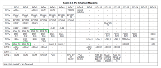
If so then the likely causes it that the SPIB interrupts (TX and RX) are likely "starving" the SCIA interrupt. By "starving" I mean that the SCI interrupts ISRs are not getting a chance to enter because they are being preempted constantly by SPIB interrupts. This is because SPIB has higher priority that SCIA (see PIE Channel Mapping table from TRM):
Depending on use-case for SPI and SCI, the best solution is to make SPI use the DMA to automatically transfer data to the memory WITHOUT interrupting. This will allow SCI (which does not have DMA) to continue having its interrupts fire.
Another potential solution is to stop SPI communications (both TX and RX) for long enough to allow SCI to get a chance to communicate as well.
One more potential solution you can try (that is not very good) is to occasionally temporarily disable SPI interrupts.For example, every 10 SPI interrupts, you disable the interrupt on exit, and let the SCIA ISR re-enable SPI. This can be dangerous though if SCI is not always transmitting. A better way to implement would be with timer interrupts that occasionally read out the data from the SCI and SPI buffers, thereby removing need for actual SCI and SPI interrupts.
Let me know if any questions on this.
Regards,
Vince
Hi Vince
Thanks for your information. I am using polling in SPI, no interrupt.
SCI A uses GPIO 2 and 3 for Tx/RX. Using below code to mux the pin
GPIO_SetupPinMux(2, GPIO_MUX_CPU1, 9);
GPIO_SetupPinMux(3, GPIO_MUX_CPU1, 9);
SPI B uses below code for mux
GPIO_SetupPinOptions(7, GPIO_INPUT, GPIO_ASYNC | GPIO_PULLUP);
// SPI_MISO
GPIO_SetupPinOptions(6, GPIO_INPUT, GPIO_ASYNC | GPIO_PULLUP);
// SPI_CS
GPIO_SetupPinOptions(29, GPIO_INPUT, GPIO_ASYNC | GPIO_PULLUP);
// SPI_CLK
GPIO_SetupPinOptions(28, GPIO_INPUT, GPIO_ASYNC | GPIO_PULLUP);
// Set PinMux to SPIB module : HK Woo
//
GPIO_SetupPinMux(6, GPIO_MUX_CPU1, 7);
GPIO_SetupPinMux(7, GPIO_MUX_CPU1, 7);
GPIO_SetupPinMux(29, GPIO_MUX_CPU1, 11);
GPIO_SetupPinMux(28, GPIO_MUX_CPU1, 11);
BR
HK
Hi,
Thanks for the follow-up. Can you verify if UART works when this line is left out of the SPI init code?
ClkCfgRegs.LOSPCP.all = HAL_SPI_LSPCLK;
It's possible changing the LSPCLK is changing the effective baud rate, and causing an issue. This shouldn't prevent transmission, but can prevent reception (RX).
Regards,
Vince