This thread has been locked.

If you have a related question, please click the "Ask a related question" button in the top right corner. The newly created question will be automatically linked to this question.

TMS320F280049C: XDS110 debugger issue

Part Number: TMS320F280049C
Other Parts Discussed in Thread: LAUNCHXL-F280049C,

Hello team,

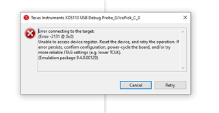
We are using XDS110 debugger as external debugger for LAUNCHXL-F280049C, we disconnected jumpers on J101,and connected XDS110 (10pin connector) to j102, But we are getting error as shown in below image 

Below is my board connections .

Can you please help me to resolve this issue.

Thanks 

  • Hello,

    Is there a reason that you're wanting to use an external debug module over the onboard XDS?

    J102 is used to bring out the XDS110 signals from the onboard XDS probe so that you can use it to debug another board. It is not used to bring signals into the TMS320F280049C device. 

    Rather, if you are wanting to use an external debugger, then you would need to use a breakout board and manually connect all of the JTAG signals. TDI and TDO are located on site 1 headers. An easier solution would be to use the Control Card with a baseboard dock since the baseboard has headers for a TI 14-pin XDS110 connector. 

    Regards,

    Peter

  • HI,

    Thanks for the reply

    Is there a reason that you're wanting to use an external debug module over the onboard XDS?

    Yes we are having problem on the launch pad LED3 was not glowing , and we observed that there is 3.3V at the point shown in below image

    Rather, if you are wanting to use an external debugger, then you would need to use a breakout board and manually connect all of the JTAG signals. TDI and TDO are located on site 1 headers. An easier solution would be to use the Control Card with a baseboard dock since the baseboard has headers for a TI 14-pin XDS110 connector. 

    Can you please explain me in detail once.

  • Hello, 

    That's strange that you're seeing a HI at that point for the LED, have you configured the GPIO connected to that LED properly? Including setting the PadConfig for that pin?

    For the LaunchPad, to connect the XDS probe, you need to manually bring the signals from the board to the XDS connector, there is no dedicated external XDS connector on the LaunchPad. If you want to use the full 4-pin JTAG, then you need to manually route the signals for TCK, TMS, TDI, and TDO. TCK and TMS are on J101, which is apart of the jumpers you removed. TDI and TDO are located on the site 1 headers, like in the image I have attached below. They are on 9 and 10 specifically.

    Let me know if you have any other questions.

    Regards,

    Peter

  • Hi, we have 2 launch pads,

    Card1- A, Card-B, we are trying to program the card B by using card A, How can I debug card B using Card A?

  • Hello,

    The easiest way to do this would be to use the 2-pin cJTAG protocol. You would then need to connect the TCK and TMS from the XDS side (top) of Card A to the TCK and TMS headers on the device side of Card B.

    To use the 4-pin regular JTAG mode would be a little harder as you would have to use a specific 10-pin to breakout connector and route the TDI and TDO from Card A to GPIO35 and GPIO37 of Card B. cJTAG protocol includes TDI and TDO information within the TMS, so it is definitely the easier method. Please let me know if you have any other questions.

    Regards,

    Peter