This thread has been locked.

If you have a related question, please click the "Ask a related question" button in the top right corner. The newly created question will be automatically linked to this question.

TMS320F28335: Programming eZdsp TMS320F28335 through XDS100v2 included in TMDSDOCK28335

Part Number: TMS320F28335
Other Parts Discussed in Thread: TMDSDOCK28335, CCSTUDIO

Hello,

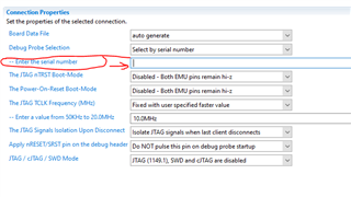
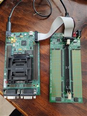
I have two different development boards based on the same DSC and I would like to know what should be taken into account (if it is possible to do) to program the processor in eZdsp TMS320F28335 externally using the programmer included in TMDSDOCK28335 docking Station baseboard JTAG interface which has a XDS100v2 probe. I connected both JTAG headers and tried to test the connection which says that fails with the following message:

This error is generated by TI's USCIF driver or utilities.

The value is '-151' (0xffffff69).
The title is 'SC_ERR_FTDI_OPEN'.

The explanation is:
One of the FTDI driver functions used during the connect
returned bad status or an error. The cause may be one or
more of: no XDS100 is plugged in, invalid XDS100 serial number,
blank XDS100 EEPROM, missing FTDI drivers, faulty USB cable.
Use the xds100serial command-line utility in the 'common/uscif'
folder to verify the XDS100 can be located.

[End: Texas Instruments XDS100v2 USB Debug Probe_0]

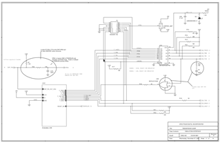
I have already checked the schematic for both boards and have been searching throughout the forum without finding any mention to this so I may have missing some particular configuration. I hope someone can help me.

Thank you very much and best regards,

Claus

  • Hi Claus,

    Their is a conflict while trying to connect two XDS100V2, you need to assign serial number associated with XDS100V2 debugger in your ccxml file.

    Through windows command line you can execute the xds100serial.exe.

    C:\ti\ccs1040\ccs\ccs_base\common\uscif\xds100serial.exe

    It will give you serial numbers of both the xds100V2 emulators, which you can program in the board configuration file (ccxml).

    Best Regards,

    Nirav

  • I think I was not clear enough but I don't have two debug probes, I just have only one and I tried to program the processor in the eZdsp development board but the connection test fails with the following result:

    [Start: Texas Instruments XDS100v2 USB Debug Probe_0]

    Execute the command:

    %ccs_base%/common/uscif/dbgjtag -f %boarddatafile% -rv -o -F inform,logfile=yes -S pathlength -S integrity

    [Result]


    -----[Print the board config pathname(s)]------------------------------------

    /home/claus/.ti/ccstudio/1/0/BrdDat/testBoard.dat

    -----[Print the reset-command software log-file]-----------------------------

    This utility has selected a 100/110/510 class product.
    This utility will load the adapter 'libjioserdesusb.so'.
    The library build date was 'Mar 17 2022'.
    The library build time was '15:40:16'.
    The library package version is '9.7.0.00213'.
    The library component version is '35.35.0.0'.
    The controller does not use a programmable FPGA.
    The controller has a version number of '4' (0x00000004).
    The controller has an insertion length of '0' (0x00000000).
    This utility will attempt to reset the controller.
    This utility has successfully reset the controller.

    -----[Print the reset-command hardware log-file]-----------------------------

    The scan-path will be reset by toggling the JTAG TRST signal.
    The controller is the FTDI FT2232 with USB interface.
    The link from controller to target is direct (without cable).
    The software is configured for FTDI FT2232 features.
    The controller cannot monitor the value on the EMU[0] pin.
    The controller cannot monitor the value on the EMU[1] pin.
    The controller cannot control the timing on output pins.
    The controller cannot control the timing on input pins.
    The scan-path link-delay has been set to exactly '0' (0x0000).

    -----[The log-file for the JTAG TCLK output generated from the PLL]----------

    There is no hardware for programming the JTAG TCLK frequency.

    -----[Measure the source and frequency of the final JTAG TCLKR input]--------

    There is no hardware for measuring the JTAG TCLK frequency.

    -----[Perform the standard path-length test on the JTAG IR and DR]-----------

    This path-length test uses blocks of 64 32-bit words.

    The test for the JTAG IR instruction path-length failed.
    The JTAG IR instruction scan-path is stuck-at-ones.

    The test for the JTAG DR bypass path-length failed.
    The JTAG DR bypass scan-path is stuck-at-ones.

    -----[Perform the Integrity scan-test on the JTAG IR]------------------------

    This test will use blocks of 64 32-bit words.
    This test will be applied just once.

    Do a test using 0xFFFFFFFF.
    Scan tests: 1, skipped: 0, failed: 0
    Do a test using 0x00000000.
    Test 2 Word 0: scanned out 0x00000000 and scanned in 0xFFFFFFFF.
    Test 2 Word 1: scanned out 0x00000000 and scanned in 0xFFFFFFFF.
    Test 2 Word 2: scanned out 0x00000000 and scanned in 0xFFFFFFFF.
    Test 2 Word 3: scanned out 0x00000000 and scanned in 0xFFFFFFFF.
    Test 2 Word 4: scanned out 0x00000000 and scanned in 0xFFFFFFFF.
    Test 2 Word 5: scanned out 0x00000000 and scanned in 0xFFFFFFFF.
    Test 2 Word 6: scanned out 0x00000000 and scanned in 0xFFFFFFFF.
    Test 2 Word 7: scanned out 0x00000000 and scanned in 0xFFFFFFFF.
    The details of the first 8 errors have been provided.
    The utility will now report only the count of failed tests.
    Scan tests: 2, skipped: 0, failed: 1
    Do a test using 0xFE03E0E2.
    Scan tests: 3, skipped: 0, failed: 2
    Do a test using 0x01FC1F1D.
    Scan tests: 4, skipped: 0, failed: 3
    Do a test using 0x5533CCAA.
    Scan tests: 5, skipped: 0, failed: 4
    Do a test using 0xAACC3355.
    Scan tests: 6, skipped: 0, failed: 5
    Some of the values were corrupted - 83.3 percent.

    The JTAG IR Integrity scan-test has failed.

    -----[Perform the Integrity scan-test on the JTAG DR]------------------------

    This test will use blocks of 64 32-bit words.
    This test will be applied just once.

    Do a test using 0xFFFFFFFF.
    Scan tests: 1, skipped: 0, failed: 0
    Do a test using 0x00000000.
    Test 2 Word 0: scanned out 0x00000000 and scanned in 0xFFFFFFFF.
    Test 2 Word 1: scanned out 0x00000000 and scanned in 0xFFFFFFFF.
    Test 2 Word 2: scanned out 0x00000000 and scanned in 0xFFFFFFFF.
    Test 2 Word 3: scanned out 0x00000000 and scanned in 0xFFFFFFFF.
    Test 2 Word 4: scanned out 0x00000000 and scanned in 0xFFFFFFFF.
    Test 2 Word 5: scanned out 0x00000000 and scanned in 0xFFFFFFFF.
    Test 2 Word 6: scanned out 0x00000000 and scanned in 0xFFFFFFFF.
    Test 2 Word 7: scanned out 0x00000000 and scanned in 0xFFFFFFFF.
    The details of the first 8 errors have been provided.
    The utility will now report only the count of failed tests.
    Scan tests: 2, skipped: 0, failed: 1
    Do a test using 0xFE03E0E2.
    Scan tests: 3, skipped: 0, failed: 2
    Do a test using 0x01FC1F1D.
    Scan tests: 4, skipped: 0, failed: 3
    Do a test using 0x5533CCAA.
    Scan tests: 5, skipped: 0, failed: 4
    Do a test using 0xAACC3355.
    Scan tests: 6, skipped: 0, failed: 5
    Some of the values were corrupted - 83.3 percent.

    The JTAG DR Integrity scan-test has failed.

    [End: Texas Instruments XDS100v2 USB Debug Probe_0]

    I add a picture to show the hardware configuration:

    To make sure that I did it fine, I followed every track in each boards' schematic. I found a little voltage drop in the voltage provided by the JTAG cable so removed the jumper JR2 in the eZdsp board to be able to power ir externally with the 5V power supply.

    From the TMDSDOCK28335 docking Station baseboard schematics it is clear that JTAG connection goes direclty through the cable, and in the eZdsp schematic, which page I copy here for clarity (page 54), the mux stays configured to the board to be programmed externally

    Regards,

    Claus

  • Hi Claus,

    There are multiple scenarios why you are not able to scan in the signals properly. Please refer to below material to root cause.

    One possible scenario could be the termination resistance on JTAG signals, how far are your signals from JTAG header to the DSP?

    Please refer to below material:

    JTAG guide: http://www.ti.com/lit/an/spracf0/spracf0.pdf  

    TI Resource Explorer (XDS): http://dev.ti.com/tirex/explore/node?node=AL8OWQmGKOMEKEatbOtBgg__FUz-xrs__LATEST

    Debugging JTAG: https://software-dl.ti.com/ccs/esd/documents/ccs_debugging_jtag_connectivity_issues.html#host-connection-error

    https://www.ti.com/lit/ug/spru655i/spru655i.pdf

    Best Regards,

    Nirav