


Part Number: TMS320F28379D
Other Parts Discussed in Thread: TIDM-DC-DC-BUCK
Hi Experts,
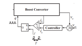
I am trying to implement the ramp generator feature available in analog comparator module of F28379D mcu for implementation of peak current mode control (as shown below).
I am unable to get clear information on the following aspects,
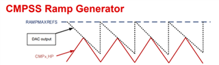
In TMS320F2837xD Dual-Core Microcontrollers Technical Reference Manual (spruhm8i, page-1773), it has been mentioned that the ramp generator produces a falling-ramp input for the high reference 12-bit DAC. The reference 12-bit DAC uses the most significant 12 bits of the RAMPSTS countdown register as its input. On setting DACSOURCE = 1, the value of RAMPSTS is loaded from RAMPMAXREFS. My doubt is as the RAMPMAXREFS is a 16-bit register, the output of voltage loop pid controller will give a value corresponding to 12-bit register as ADC of voltage sensor is 12 bit. Do I need to converter the 12-bit value (range 0-4095) of ic into 16-bit value (range 0-65535) and also is this changed value will be assigned to RAMPMAXREFS?
How to choose the value of RAMPDECVAL?
The low 4 bits of the RAMPSTS countdown register effectively act as a prescale for the falling -ramp rate configurable with RAMPDECVALA. How this concept works?
Experts please share your valuable suggestions in the above quires?
Note: I have referred to the documents like TIDM-DC-DC-BUCK, Digital Peak Current Mode Control with Slope Compensation Using the TMS320F2803x and spruhm8i, but not able to get proper answer to my doubts.
