


Part Number: TMS320F28377D
Hi.
I have a special PWM waveform that i need to produce for my converter. It's shown in Fig.1. EPWM2 chanel has be updated twice in a switching cycle. (double switching).
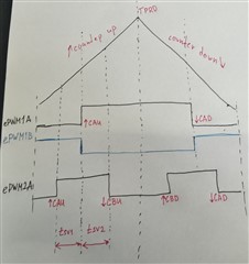 Figure 1. Expected PWM waveform before Deadband.
When I apply RED and FED of 500ns deadband to EPWM1 chanel what happens is: 500ns deadband is cut from the front part of the pulse of EPWM1A for RED, while FED is applied to EPWM1B and cuts 500ns from it leaving EPWM1A unchanged when counter goes down (Fig.2 below). So what I get is an assymetric waveform for EPWM1A chanel the consiquencies of which are the dwell times of the EPWM2 chanel are applied incorrectly (tsv1 dwell time is increased by 500ns when the counter is up, and tsv2 is reduced by 500ns) leading to the unbalanced and distorted generation of the voltage space vector.
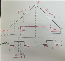 Figure 2. PWM waveform after Deadband applied.
My question is: How can I apply FED to ePWM1A chanel instead of ePWM1B? Or how can I add RED of 500ns that is cut from the front part to the back (when counter goes down) to compensate for the imbalance on 28377D?
Thank you for your responce!!!
