This thread has been locked.
If you have a related question, please click the "Ask a related question" button in the top right corner. The newly created question will be automatically linked to this question.
Hi,
I was talking to Nima Eskandari but the thread is closed, so I try making this related question, instead.
Hi Nima, here I am, bothering you again... I hope, we can reopen the thread!
To continue with the interrupts question, "TMS320F28379D: ePWM interrupts on TBCTR = CMPA and also on TBCTR = CMPB",
I have made my tests and your idea works good, but I found out that I can also use Period on ePWMxA and CMPB on the ePWMxB to generate the interrupts I need. It seems to be more simple...
However, the timing does not work as I expected:
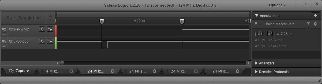
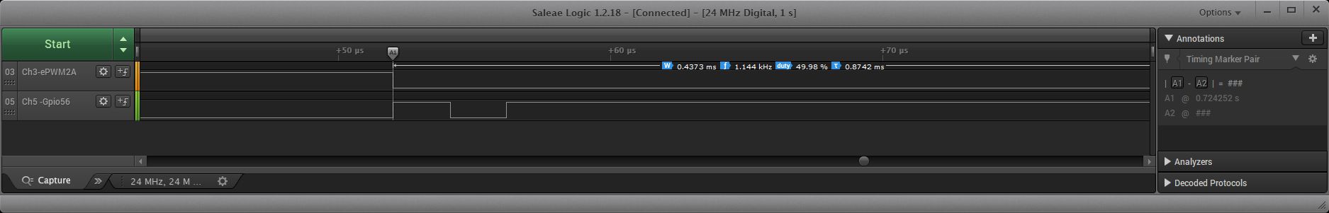
Interrupts A and B on ePWM2 are supposed to activate an interrupt on ePWM1, which clears GPIO56 pin to low, just after the A-pin of the ePWM1 goes high.
Ideally, this should happen after around 5 uS, but this is not so crucial, as long as this remains allways the same.
The interrupts are working, but the timing not.
GPIO56 goes low at any moment, but not on the moment I want.
My logic analyzer shows, also, that the interrupts of ePWM2 are comming some (randomly) 4 till 7 uS before the changing to Low or High happens on the ePWM2-output A,
while I am expecting it just on this time or slightly after, but not before.
So, I have two questions:
1 - Why does the interrupt comes so far before the time it should come?
This is, so far, not so disturbing for my application, but:
2 - Why is Pin56 going low randomly in time?
I know, there is a propagation delay of around 14 SYSCLK till the ISR is called, but this does not explain this behaviour.
Te relevant parts of the code are included.
I wish you a nice weekend, or, better, a nice week!
Gustavo
myPeriod = 730; // Freq = 67,8 kHz, Period 14,75 uS myDutyA = 718; // duty is 98,31% myDutyB = 50; myDutyFineA = 1; myDutyFineB = 1; myPeriodGrand = 786; myDutyGrand = 451; // // epwm1_isr // __interrupt void epwm1_isr(void) { EPwm1Regs.ETSEL.bit.INTEN = 0; // Disable ePWM1 INT, until epwm2_isr enables it again GpioDataRegs.GPBCLEAR.bit.GPIO61 = 1; // This should allways happen at the same place, ideally 6uS after ePWM1 goes High (which, in turn, remains High during 14,38 uS) DELAY_US(100); // this is only for clarity. Here is some code GpioDataRegs.GPBSET.bit.GPIO61 = 1; // set GPIO61 high if(modo == 0b110) { modo = 0b010; // 100: time-base counter equal to CMPA when the timer is incrementing DELAY_US(5); // Here is some code } else { modo = 0b110; // 110: time-base counter equal to CMPB when the timer is incrementing DELAY_US(5); // Here is some code } EPwm2Regs.ETSEL.bit.INTSEL = modo; PieCtrlRegs.PIEACK.all = PIEACK_GROUP3; // Acknowledge this interrupt to receive more interrupts from group 3 } // // epwm2_isr __interrupt void epwm2_isr(void) { EPwm1Regs.ETCLR.bit.INT = 1; // Clear INT flag for ePWM1 timer EPwm1Regs.ETSEL.bit.INTEN = 1; // Enable INT on ePWM1 EPwm2Regs.ETCLR.bit.INT = 1; // Clear INT flag for this timer PieCtrlRegs.PIEACK.all = PIEACK_GROUP3; // Acknowledge this interrupt to receive more interrupts from group 3 } void HRPWM1_Config(myPeriod) { EPwm1Regs.TBCTL.bit.PRDLD = TB_IMMEDIATE; // set Immediate load EPwm1Regs.TBPRD = myPeriod; // PWM frequency EPwm1Regs.CMPA.bit.CMPA = myDutyA; // set duty for ePWM1A EPwm1Regs.CMPA.bit.CMPAHR = (myDutyFineA << 8); // set duty fine for ePWM1A EPwm1Regs.CMPB.bit.CMPB = myDutyB; // set duty for ePWM1B - for the interrupt EPwm1Regs.CMPB.all |= (myDutyFineB << 8); // set HR-duty for ePWM1B - for the interrupt EPwm1Regs.TBPHS.all = 0; EPwm1Regs.TBCTR = 0; EPwm1Regs.TBCTL.bit.CTRMODE = TB_COUNT_UP; EPwm1Regs.TBCTL.bit.PHSEN = TB_DISABLE; EPwm1Regs.TBCTL.bit.SYNCOSEL = TB_SYNC_DISABLE; EPwm1Regs.TBCTL.bit.HSPCLKDIV = TB_DIV1; EPwm1Regs.TBCTL.bit.CLKDIV = TB_DIV1; EPwm1Regs.CMPCTL.bit.LOADAMODE = CC_CTR_ZERO; EPwm1Regs.CMPCTL.bit.LOADBMODE = CC_CTR_ZERO; EPwm1Regs.CMPCTL.bit.SHDWAMODE = CC_SHADOW; EPwm1Regs.CMPCTL.bit.SHDWBMODE = CC_SHADOW; EPwm1Regs.AQCTLA.bit.ZRO = AQ_SET; EPwm1Regs.AQCTLA.bit.CAU = AQ_CLEAR; EPwm1Regs.AQCTLB.bit.ZRO = AQ_SET; EPwm1Regs.AQCTLB.bit.CBU = AQ_CLEAR; // INT on CMPB EPwm1Regs.ETSEL.bit.INTEN = 0; // Disable INT - It will be enabled in epwm2_isr EPwm1Regs.ETPS.bit.INTPSSEL = 0x0; EPwm1Regs.ETPS.bit.INTPRD = 0x2; // Generate an interrupt on the second event EPwm1Regs.ETSEL.bit.INTSELCMP = 0x0; // 0: time-base counter equal to CMPB when the timer is incrementing EPwm1Regs.ETSEL.bit.INTSEL = 0x6; // 110: time-base counter equal to CMPB. EALLOW; EPwm1Regs.HRCNFG.all = 0x0; EPwm1Regs.HRCNFG.bit.EDGMODE = HR_FEP; EPwm1Regs.HRCNFG.bit.CTLMODE = HR_CMP; EPwm1Regs.HRCNFG.bit.HRLOAD = HR_CTR_ZERO; EPwm1Regs.HRCNFG.bit.EDGMODEB = HR_FEP; EPwm1Regs.HRCNFG.bit.CTLMODEB = HR_CMP; EPwm1Regs.HRCNFG.bit.HRLOADB = HR_CTR_ZERO; EDIS; } // // HRPWM2_Config // void HRPWM2_Config(period) // low freq. { EPwm2Regs.TBCTL.bit.PRDLD = TB_IMMEDIATE; // set Immediate load EPwm2Regs.TBPRD = myPeriodGrand; // PWM frequency EPwm2Regs.CMPB.bit.CMPB = myDutyGrand; // set duty EPwm2Regs.CMPA.bit.CMPA = myDutyGrand; // set duty ???? EPwm2Regs.TBPHS.all = 0; EPwm2Regs.TBCTR = 0; EPwm2Regs.TBCTL.bit.CTRMODE = TB_COUNT_UP; // Start ePWM in COUNT_UP mode EPwm2Regs.TBCTL.bit.PHSEN = TB_DISABLE; EPwm2Regs.TBCTL.bit.SYNCOSEL = TB_SYNC_DISABLE; EPwm2Regs.TBCTL.bit.HSPCLKDIV = 0b100; // to have a very low freq EPwm2Regs.TBCTL.bit.CLKDIV = 0x4; // Time Base Clock Pre-Scale EPwm2Regs.CMPCTL.bit.LOADAMODE = CC_CTR_ZERO; EPwm2Regs.CMPCTL.bit.LOADBMODE = CC_CTR_ZERO; EPwm2Regs.CMPCTL.bit.SHDWAMODE = CC_SHADOW; EPwm2Regs.CMPCTL.bit.SHDWBMODE = CC_SHADOW; EPwm2Regs.AQCTLA.bit.ZRO = AQ_SET; EPwm2Regs.AQCTLA.bit.CAU = AQ_CLEAR; EPwm2Regs.AQCTLB.bit.ZRO = AQ_SET; EPwm2Regs.AQCTLB.bit.CBU = AQ_CLEAR; // need INT on CMPB and on Period: EPwm2Regs.ETPS.bit.INTPSSEL = 0x0; EPwm2Regs.ETPS.bit.INTPRD = 0x1; // 01: Generate an interrupt on the first event INTCNT = 01 (first event) EPwm2Regs.ETSEL.bit.INTSELCMP = 0x0; // time-base counter equal to CMPA or CMPB when the timer is incrementing to INTSEL selection mux. EPwm2Regs.ETSEL.bit.INTSEL = modo; // start with 110: time-base counter equal to CMPB. In the epwm1_isr swap ot between 010 (for Period) and 110 (for CMPB) // I do not use HRPWM here. I guess I do not need this? // EALLOW; // EPwm2Regs.HRCNFG.all = 0x0; // EPwm2Regs.HRCNFG.bit.EDGMODE = HR_FEP; // EPwm2Regs.HRCNFG.bit.CTLMODE = HR_CMP; // EPwm2Regs.HRCNFG.bit.HRLOAD = HR_CTR_ZERO; // EPwm2Regs.HRCNFG.bit.EDGMODEB = HR_FEP; // EPwm2Regs.HRCNFG.bit.CTLMODEB = HR_CMP; // EPwm2Regs.HRCNFG.bit.HRLOADB = HR_CTR_ZERO; // EDIS; }
Hi Nima,
thanks for answering.
I include a simplified screenshot.
What you see is:
On Ch2 is the signal of ePWM2. On this edge (marker A2), CMPB triggers the interrupt.
On this test, ePWM2 startet just there. Before this, the signal was all the time low.
(I wanted to be sure, no counting was made before, which could trigger a waiting interrupt. Anyway, this pattern continues like this all the time)
On Ch5 is Gpio56 going low inside the ISR. (marker A1)
As you can see, Pin56 goes low 7,25 uS before the ePWM-Pin goes high.
I realise, there is a delay between the CMPB count and the actual toggling of the pin, but
are 7,25 uS not too much?
(We have to add the propagation delay from the interrupt itself, plus the time needed to toggle pin 56 too)
ePWM2 is slow (496 Hz) Is this the reason?
EPwm2Regs.TBPRD = 786;
EPwm2Regs.CMPB.bit.CMPB = 451;
EPwm2Regs.CMPA.bit.CMPA = 451;
with
EPwm2Regs.TBCTL.bit.HSPCLKDIV = 0b100;
EPwm2Regs.TBCTL.bit.CLKDIV = 0x4;
A I said, this is not disturbing in my application, but it could be interesting to know the reason, for the future.
Best regards,
Hi Nima, thanks for answering.
Yes, I see the GPOI toggle around 7 uS before the ePWM pin toggles on CMPB
Hi Nima,
sorry for the delay, I was on travel again.
Here is a small code (I cleaned it from all other tasks) and a screenshot where you can see what is happening.
The time between the toggling of GPIO56 and ePWB2B (GPIO3) on CPMB is shorter (4.875 uS) then the one on Period (7.375 uS)
Maybe is my equipment?
Strange is that the interrupt on ePWM1 does what I expect.
#include "F28x_Project.h" // Function Prototypes void initSerialPins(void); void HRPWM1_Config(int); void HRPWM2_Config(int); __interrupt void epwm1_isr(void); __interrupt void epwm2_isr(void); Uint16 modo,miPeriod,miPeriodFine,miDutyA,miDutyB,miPeriodGrand,miDutyGrand; #define PWM_CH 9 // # of PWM channels volatile Uint16 EPwmTZIntCount[9],Test_flag1,ph_dly; // 0,18 are extra volatile struct EPWM_REGS *ePWM[10]; // vars for flags void main(void) { //########################################################################### // ePWM1 miPeriod = 730; miPeriodFine = 1; miDutyA = 718; miDutyB = 250; // ePWM2 miPeriodGrand = 512; miDutyGrand = 256; modo = 0b110; //########################################################################### EALLOW; InitSysCtrl(); // Initialize System Control:PLL, WatchDog, enable Peripheral Clocks EDIS; InitGpio(); // Configure default GPI InitEPwmGpio(); // EPWM1A and EPWM1B initSerialPins(); ePWM[1] = &EPwm1Regs; // PWM Address Map ePWM[2] = &EPwm2Regs; // PWM Address Map // Clear all interrupts and initialize PIE vector table DINT; InitPieCtrl(); IER = 0x0000; IFR = 0x0000; InitPieVectTable(); EALLOW; PieVectTable.EPWM1_INT = &epwm1_isr; PieVectTable.EPWM2_INT = &epwm2_isr; EDIS; IER |= M_INT3; // Enable CPU INT3 which is connected to EPWM1-3 INT PieCtrlRegs.PIEIER3.bit.INTx1 = 1; PieCtrlRegs.PIEIER3.bit.INTx2 = 1; EINT; // Enable Global interrupt INTM //########################################################################### // Config ePWM1 and ePWM2 EALLOW; CpuSysRegs.PCLKCR0.bit.TBCLKSYNC = 0; // This will stop the time-base clock within any enabled ePWM module. EDIS; HRPWM1_Config(miPeriod); HRPWM2_Config(miPeriodGrand); EALLOW; CpuSysRegs.PCLKCR0.bit.TBCLKSYNC = 1; // This will start the time-base clock within any enabled ePWM module. EDIS; //########################################################################### GpioDataRegs.GPBSET.bit.GPIO56 = 1; // GPIO56 to HIGH DELAY_US(50); // Some tasks here //########################################################################### // Start ePWM2 and Activate INTs EPwm2Regs.TBCTL.bit.CTRMODE = TB_COUNT_UP; // Start ePWM2 in COUNT_UP mode DELAY_US(5000); // Luego ESPERAR otros 10 mS antes de autorizar interrupts de ePWM2 EPwm2Regs.ETPS.bit.INTPRD = 0x1; // 01: Generate an interrupt on the first event INTCNT = 01 (first event) //########################################################################### for (;;) {} // loop forever. } //////////////// END of MAIN /////////////// //########################################################################### __interrupt void epwm1_isr(void) { EPwm1Regs.ETPS.bit.INTPRD = 0x0; // deactivate int on ePWM1 until the next int on ePWM2 GpioDataRegs.GPBCLEAR.bit.GPIO61 = 1; if( modo == 0b110) { modo = 0b100; // Select INT 100 for the next Int on ePWM2: time-base counter equal to CMPC when the timer is incrementing } else { modo = 0b110; // Select INT 110 for the next Int on ePWM2: time-base counter equal to CMPD when the timer is incrementing } //########################################################################### DELAY_US(50); // Some tasks here //########################################################################### GpioDataRegs.GPBSET.bit.GPIO61 = 1; EPwm2Regs.ETSEL.bit.INTSEL = modo; // Change time-base counter on ePWM2 PieCtrlRegs.PIEACK.all = PIEACK_GROUP3; // Acknowledge this interrupt to receive more interrupts from group 3 } //########################################################################### __interrupt void epwm2_isr(void) { GpioDataRegs.GPBTOGGLE.bit.GPIO56 = 1; EPwm1Regs.ETCLR.bit.INT = 1; // Clear INT flag for ePWM1 timer EPwm1Regs.ETPS.bit.INTPRD = 0x2; // activate interrupt on second event EPwm2Regs.ETCLR.bit.INT = 1; // Clear INT flag for this timer PieCtrlRegs.PIEACK.all = PIEACK_GROUP3; // Acknowledge this interrupt to receive more interrupts from group 3 } //########################################################################### void HRPWM1_Config(period) // EPwm and HRPWM register initialization - Ajusta la frecuencia del PWM para la cuerda { EPwm1Regs.TBCTL.bit.PRDLD = TB_IMMEDIATE; // set Immediate load EPwm1Regs.TBPRD = miPeriod; // PWM frequency = 1 / miPeriod EPwm1Regs.CMPA.bit.CMPA = miDutyA; // set duty for ePWM1A - para la frecuencia cuerda EPwm1Regs.CMPB.bit.CMPB = miDutyB; // set duty for ePWM1B - para interrupt para el ADC EPwm1Regs.TBPHS.all = 0; EPwm1Regs.TBCTR = 0; EPwm1Regs.TBCTL.bit.CTRMODE = TB_COUNT_UP; // Start ePWM1. EPwm1Regs.TBCTL.bit.PHSEN = TB_DISABLE; EPwm1Regs.TBCTL.bit.SYNCOSEL = TB_SYNC_DISABLE; EPwm1Regs.TBCTL.bit.HSPCLKDIV = TB_DIV1; EPwm1Regs.TBCTL.bit.CLKDIV = TB_DIV1; EPwm1Regs.CMPCTL.bit.LOADAMODE = CC_CTR_ZERO; EPwm1Regs.CMPCTL.bit.LOADBMODE = CC_CTR_ZERO; EPwm1Regs.CMPCTL.bit.SHDWAMODE = CC_SHADOW; EPwm1Regs.CMPCTL.bit.SHDWBMODE = CC_SHADOW; EPwm1Regs.AQCTLA.bit.ZRO = AQ_SET; EPwm1Regs.AQCTLA.bit.CAU = AQ_CLEAR; EPwm1Regs.AQCTLB.bit.ZRO = AQ_SET; EPwm1Regs.AQCTLB.bit.CBU = AQ_CLEAR; EPwm1Regs.ETSEL.bit.INTEN = 1; // Enable INT EPwm1Regs.ETPS.bit.INTPSSEL = 0x0; // EPWMxINTn Pre-Scale Selection Bits 0: Selects ETPS [INTCNT, and INTPRD] registers to determine frequency of events (interrupt once per event). EPwm1Regs.ETPS.bit.INTPRD = 0x0; // do not activate here, but inside the ePWM2 ISR !!! set as 02: Generate an interrupt on the second event INTCNT = 02 (second event) EPwm1Regs.ETSEL.bit.INTSELCMP = 0x0; // 0: Enable event time-base counter equal to CMPA or CMPB to INTSEL selection mux. EPwm1Regs.ETSEL.bit.INTSEL = 0x6; // 110: time-base counter equal to CMPB EALLOW; EPwm1Regs.HRCNFG.all = 0x0; EPwm1Regs.HRCNFG.bit.EDGMODE = HR_FEP; EPwm1Regs.HRCNFG.bit.CTLMODE = HR_CMP; EPwm1Regs.HRCNFG.bit.HRLOAD = HR_CTR_ZERO; EPwm1Regs.HRCNFG.bit.EDGMODEB = HR_FEP; EPwm1Regs.HRCNFG.bit.CTLMODEB = HR_CMP; EPwm1Regs.HRCNFG.bit.HRLOADB = HR_CTR_ZERO; EDIS; } //########################################################################### void HRPWM2_Config(period) // low freq. To toogle mode (VOhm or VnoOhm) { EPwm2Regs.TBCTL.bit.PRDLD = TB_IMMEDIATE; // set Immediate load EPwm2Regs.TBPRD = miPeriodGrand; // PWM frequency EPwm2Regs.CMPA.bit.CMPA = miDutyGrand; // set duty EPwm2Regs.CMPB.bit.CMPB = miDutyGrand; // set duty //++++++++++++++++++++++++++++++++++++++++++++++++++++++++++++++++++++++++++++++++++++++++++++++++++++++++++++++++++++++++++++++++++++++++++++++++++++++++++++++++++++++++++++++++++ EPwm2Regs.CMPC = miPeriodGrand; EPwm2Regs.CMPD = miDutyGrand; //++++++++++++++++++++++++++++++++++++++++++++++++++++++++++++++++++++++++++++++++++++++++++++++++++++++++++++++++++++++++++++++++++++++++++++++++++++++++++++++++++++++++++++++++++ EPwm2Regs.TBPHS.all = 0; EPwm2Regs.TBCTR = 0; EPwm2Regs.TBCTL.bit.PHSEN = TB_DISABLE; EPwm2Regs.TBCTL.bit.SYNCOSEL = TB_SYNC_DISABLE; EPwm2Regs.TBCTL.bit.HSPCLKDIV = 0b100; EPwm2Regs.TBCTL.bit.CLKDIV = 0x4; // Time Base Clock Pre-Scale Bits - These bits select the time base clock pre-scale value (TBCLK = EPWMCLK/(HSPCLKDIV * CLKDIV): EPwm2Regs.CMPCTL.bit.LOADAMODE = CC_CTR_ZERO; EPwm2Regs.CMPCTL.bit.LOADBMODE = CC_CTR_ZERO; EPwm2Regs.CMPCTL.bit.SHDWAMODE = CC_SHADOW; EPwm2Regs.CMPCTL.bit.SHDWBMODE = CC_SHADOW; EPwm2Regs.AQCTLA.bit.ZRO = AQ_SET; EPwm2Regs.AQCTLA.bit.CAU = AQ_CLEAR; EPwm2Regs.AQCTLB.bit.ZRO = AQ_SET; EPwm2Regs.AQCTLB.bit.CBU = AQ_CLEAR; EPwm2Regs.ETPS.bit.INTPSSEL = 0x0; // EPWMxINTn Pre-Scale Selection Bits 0: Selects ETPS [INTCNT, and INTPRD] registers to determine frequency of events (interrupt once per event). EPwm2Regs.ETSEL.bit.INTEN = 1; // Enable INT EPwm2Regs.ETSEL.bit.INTSELCMP = 0x1; // EPWMxINT Compare Register Selection Options 1: Enable event time-base counter equal to CMPC or CMPD when the timer is incrementing to INTSEL selection mux. // Start with interrupt after Duty (CMPD) EPwm2Regs.ETSEL.bit.INTSEL = modo; // Select INT 110: time-base counter equal to CMPD when the timer is incrementing // inside ePWM1interrupt, change to interrupt after Period (CMPC) // EPwm2Regs.ETSEL.bit.INTSEL = 0b100; // Select INT 100: time-base counter equal to CMPC when the timer is incrementing EALLOW; EPwm2Regs.HRCNFG.all = 0x0; EPwm2Regs.HRCNFG.bit.EDGMODE = HR_FEP; EPwm2Regs.HRCNFG.bit.CTLMODE = HR_CMP; EPwm2Regs.HRCNFG.bit.HRLOAD = HR_CTR_ZERO; EPwm2Regs.HRCNFG.bit.EDGMODEB = HR_FEP; EPwm2Regs.HRCNFG.bit.CTLMODEB = HR_CMP; EPwm2Regs.HRCNFG.bit.HRLOADB = HR_CTR_ZERO; EDIS; } //########################################################################### void initSerialPins() { EALLOW; GpioCtrlRegs.GPBGMUX2.bit.GPIO56 = 0; // GPIO56 = GPIO56 GpioCtrlRegs.GPBMUX2.bit.GPIO56 = 0; // GPIO56 = GPIO56 GpioCtrlRegs.GPBPUD.bit.GPIO56 = 0; // Enable pull-up on GPIO56 GpioCtrlRegs.GPBDIR.bit.GPIO56 = 1; // configure GPIO56 as OUTPUT GpioCtrlRegs.GPBGMUX2.bit.GPIO61 = 0; // GPIO61 = GPIO61 GpioCtrlRegs.GPBMUX2.bit.GPIO61 = 0; // GPIO61 = GPIO61 GpioCtrlRegs.GPBPUD.bit.GPIO61 = 0; // Enable pull-up on GPIO61 GpioCtrlRegs.GPBDIR.bit.GPIO61 = 1; // configure GPIO61 as OUTPUT EDIS; } //###########################################################################
Best regards
Gustavo
Hi Nima,
I think, I found the reason for this problem. I do not have the solution, however:
Following your idea, thet the ISR of ePWM1 was making trouble, I cleaned everything, leaving just the ePWM2-ISR. No Int on ePWM1, no interaction of ePWM1 with ePWM2.
The ISR looks like this:
Pin56 is my test pin
__interrupt void epwm2_isr(void)
{
GpioDataRegs.GPBTOGGLE.bit.GPIO56 = 1;
DELAY_US(1);
GpioDataRegs.GPBTOGGLE.bit.GPIO56 = 1;
DELAY_US(1);
GpioDataRegs.GPBTOGGLE.bit.GPIO56 = 1;
DELAY_US(1);
EPwm2Regs.ETCLR.bit.INT = 1;
PieCtrlRegs.PIEACK.all = PIEACK_GROUP3;
}
The problem persists.
The reason seems to be by the value of TBCTL.bit.CLKDIV
Any value of CLKDIV higher than 0 causes the ISR to start earlier.
But also any frequency lower than 1.14 kHz is problem.
As I have in my code:
TBPRD = 512
EPwm2Regs.TBCTL.bit.HSPCLKDIV = 0b100;
EPwm2Regs.TBCTL.bit.CLKDIV = 0x4;
Which I have set to get a very low freq (761 Hz).
GPIO56 toggles 4.66 uS BEFORE the ePWM-Pin goes HIGH
See the screenshotD
Changing this to
TBPRD = 512
EPwm2Regs.TBCTL.bit.HSPCLKDIV = 0b100;
EPwm2Regs.TBCTL.bit.CLKDIV = 0x0;
Which gives a higher freq (12.18 kHz).
GPIO56 toggles 83.33 uS AFTER the ePWM-Pin goes HIGH
See the screenshotE
This problem starts when the frequency is lower than 1.14 kHz:
Setting
TBPRD = 0x1111
EPwm2Regs.TBCTL.bit.HSPCLKDIV = 0b101;
EPwm2Regs.TBCTL.bit.CLKDIV = 0x0;
Which gives a freq of 1.144 kHz.
GPIO56 toggles EXACTLY with ePWM-Pin going HIGH
See the screenshotF
Setting
TBPRD = 0x1111
EPwm2Regs.TBCTL.bit.HSPCLKDIV = 0b110;
EPwm2Regs.TBCTL.bit.CLKDIV = 0x0;
Which gives a freq of 953.3 kHz.
GPIO56 toggles 83.3 nS BEFORE the ePWM-Pin goes HIGH
See the screenshotG
Now, I think I can solve this for me by using the event-trigger prescaling logic to get a lower interrupt frequency without setting CLKDIV higher than 0.
However, I would like to know, if this behaviour is normal when using very low pwm frequencys.
A nice day for you!
Best regards,
Gustavo