This thread has been locked.
If you have a related question, please click the "Ask a related question" button in the top right corner. The newly created question will be automatically linked to this question.
Hello,
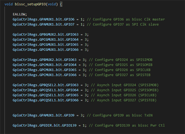
I'm currently working with LAUNCHXL-F28379D and BOOSTXL-POSMGR and I want to read the data from RLS-BRD01_11 absolute encoder which is multiturn (I attached the data sheet of the encoder to this message). I tried to use Texas example for BiSS-C protocol but I couldn't adopt it for my system and encoder properly and I faced with error. I want to see which parameter I should change? I changed the data length, yet it's not working. In addition, this is the path to the example:
C:\ti\controlSUITE\development_kits\BOOSTXL_POSMGR\v01_01_00_00\bissc-F28379DLpad-S2\examples\PM_bissc_SystemTest
Thanks.
Hi Steve,
What type of error are you getting? If you observe the waveforms sent/received by the f2837xD do they look correct?
Regards
Lori
I don't get any error, the communication is not correct with encoder, because based on the user guide of C2000 Position Manager BISS-C Library some of the properties should be changed based on the encoder properties I told you. I attached the user guide and the piece of the code that should be modified here. Another question related to the code is why for BISS_SCD_CRC_POLY1 and BISS_CD_CRC_POLY1 they are 0x03?? Shouldn't be 0x43 and 0x13 respectively?
//If Control data interface is being used this bit should be set to 1 else 0.
#define BISS_ENCODER_HAS_CD_INTERFACE 1
//Number of position bits for the encoder in use
#define BISS_POSITION_BITS 24
//Number of CRC bits for the encoder in use – this is defined as 6 for BiSS-C
#define BISS_POSITION_CRC_BITS 6
//Number of bits of Single Cycle Data Polynomial
#define BISS_SCD_CRC_NBITS_POLY1 6
// Single Cycle Data Polynomial
#define BISS_SCD_CRC_POLY1 0x03 //x^6 + x + 1 (inverted output) 1000011
//Number of bits of Control Data Polynomial
#define BISS_CD_CRC_NBITS_POLY1 4
//Control Data Polynomial
#define BISS_CD_CRC_POLY1 0x03 //x^4 + x + 1 (inverted output) 10011
//Size of CRC tables for Control Data and Single Cycle Data – should be set to 256
#define BISS_SCD_CRC_SIZEOF_TABLE 256
#define BISS_CD_CRC_SIZEOF_TABLE 256
Also, I monitored the SPIB clock and ePWM4A and ePWM4B, and I didn't get signal from them.
properties should be changed based on the encoder properties
Typically only the position bits will need to be changed to match the encoder.
Another question related to the code is why for BISS_SCD_CRC_POLY1 and BISS_CD_CRC_POLY1 they are 0x03?? Shouldn't be 0x43 and 0x13 respectively?
The CRC algorithm used for this example does not require the leading 1. The 1 is implied by the size.
Also, I monitored the SPIB clock and ePWM4A and ePWM4B, and I didn't get signal from them.
For the SPICLK, double check the pin you are monitoring. It is incorrect in the design guide. Here is the setup in the code. The comments match the figure, but at some point the actual code was changed to use other pins.
SPICLIB is on pin 65
The CLB on the MCU drives the SPICLK via GPIO7.
The waveform should look like this:
My GPIO setup now is correct and I receive the clock.
But My CRC bit is increasing.
The Position data in my encoder is 30 (16 bits multiturn + 14 bits single turn).
I don't know where is the problem. I attached the screenshot of the data package corresponding to the encoder I'm using.
This is also my code for bissc.h file.
Besides, I'm using this path for the example
C:\ti\controlSUITE\libs\app_libs\position_manager\v01_02_00_00\bissc\examples\PM_bissc_SystemTest
Steve,
I reviewed reported issues and found one report for the CRC of 32 bits (30 position + error + warning) . The workaround is the following two changes:
Let me know if this resolves the issue you see.
Lori,
Could you please send me the path you are using?
Because in the one I'm using I could not the lines you modified and some variable like numBitsPosCrc is not defined.
Also, I think one of the function that you modified is PM_bissc_getCRC, which I don't have access to go into this function.
Thank you
Hi Steve,
Apologies, I forgot the CRC was within the library. I've attached the source file. You should be able to modify it to fit your needs and give the function a new name. Then the calls to the CRC can be redirected to the new function.
Best regards
Lori
/cfs-file/__key/communityserver-discussions-components-files/171/pm_5F00_bissc_5F00_crc.c
Lori,
Thanks for the code.
Besides the CRC, I monitored the SLO+ and SLO- signals and they were same (they should be differential).
I attached an image of my setup here and the signals SLO+(Blue) and SLO-(Yellow).
When I'm monitoring these two signal from the device that its manufacture made, they are differential but when I'm using BOOSTXL_POSMGR this is the result.