Other Parts Discussed in Thread: CONTROLSUITE, DRV8312, LM5109
Hello TI experts,
I am going to drive a PMSM motor using foc algorithm. I have designed a board which contains a f28065 microcontroller. In order to do that I started with ti application notes. Then I customised it according to my board.
In my board I have connected hall-effect sensors to ecap1, ecap2 and ecap3 pins of the controller.
I've got some questions.
1- in this application note, pwms are modified in interrupt servic routine of pwm1. When tbctr resets the interrupt is generated. My question is if do other pwms need to be synced with pwm1? I mean the value of tbctr register of other pwms shouldn't be the same as pwm1?
2- as my motor is not equipped with encoder and I only have 30 edges of hall sensors, is it possible to do position control precisely?
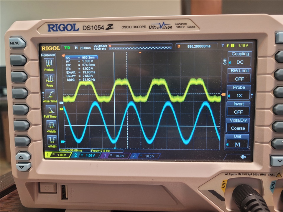
3- when I set buildlevel to level3, the motor rotates in open loop mode. But it generates lots of noise.
I apologise if my questions are very basic.
Thanks