Because of the holidays, TI E2E™ design support forum responses will be delayed from Dec. 25 through Jan. 2. Thank you for your patience.

This thread has been locked.

If you have a related question, please click the "Ask a related question" button in the top right corner. The newly created question will be automatically linked to this question.

TMS320F28335: TMS320F28335

Part Number: TMS320F28335

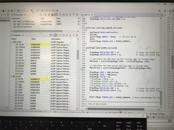
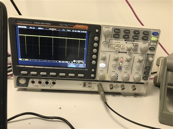
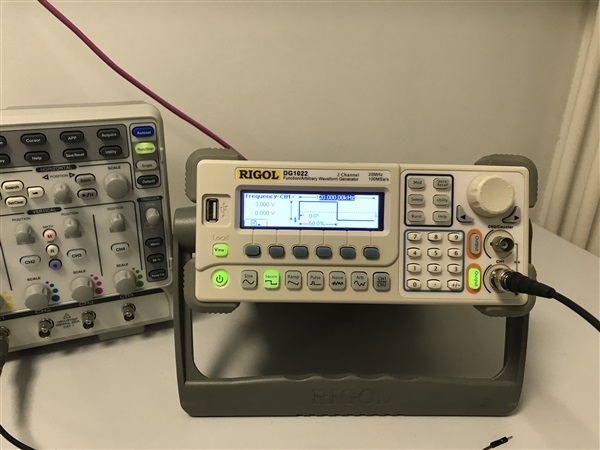
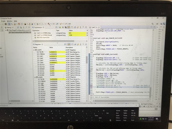
I generated a square pulse signal 1 KhZ 50% duty cycle from the function generator and applied at port GPIO24(Ecap1) using Ecap module . The signal is shown on the watch window and passed to GPIO25 (Ecap 2) which is visible at the oscilloscope. Firstly, the signal has a delay and It generates output after around 4-5 seconds and sometimes longer as I increase the freq in step. Please see the picture below for 1KHz 50% dutycycle PWM at the oscilloscope.

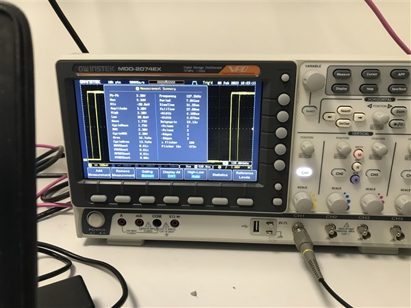
But once I changed the frequency from 1KHz to 120Khz  at 50% or a different duty cycle from the generator and waited for some time or longer period. Again the output doesn't come up and it shows garbage values in the oscilloscope. Please see the results pictures below.

The code is given as,

Community members, please suggest accordingly.

Arsalan

  • Hi Arsalan,

    Your TSCTR or Time stamp counter is reaching the max value of 2^32-1, after you set your period and leave the ISR try setting the TSCTR to zero.

    This may help with your delay issue you're seeing.

     ECap2Regs.TSCTR = 0;                        // Clear the counter

  • Hi Ryan,

    Thanks for your reply.

    The delay issue was resolved after the TSCTR counter is cleared just after the PWM_Period setting. But I noticed two other issues after that,

    1- Just power off the generator signal, the signal remains in the buffer and doesn't clear. I tried to clear the interrupts and counter settings in the code but it didn't work. Please see the pictures after turning off the generator signal and oscilloscope retain the signal having peaks neither stable high nor low.

    2- Once I change the frequency from 1KHz to 120Khz  at 50% or a different duty cycle from the generator, the signal doesn't remain stable at that specific freq / dutycycle. Both frequency and duty cycle vary. Please see the results pictures below.

    Looking forward to your feedback

    Arsalan

  • Hi Arsalan,

    For your first problem that seems to be something that will need additional logic to check if the input capture is not receiving any input and then you can set the CAP1/CAP2 registers to 0, turning off the CTR etc.

    The second problem might be because your interrupt is occurring every third capture edge, and thus updating the PWM period/duty cycle, as well as resetting the counter to zero. Maybe you can add some additional logic to allow the interrupt to only occur after x events so the PWM period/duty cycle registers can hold their values for a certain period and see if this stabilizes the outputs.

    Best,

    Ryan Ma

  • Hi Ryan,

    Thanks for your reply. My previous code is given below:

    Q: For your first problem that seems to be something that will need additional logic to check if the input capture is not receiving any input and then you can set the CAP1/CAP2 registers to 0, turning off the CTR etc.

    For the suggestion of the first problem: I used the while loop at line 241 at the ECCLR.bit.INT and then set the values '0' for ECap1/2 and TSCR =0.

    Q: The second problem might be because your interrupt is occurring every third capture edge, and thus updating the PWM period/duty cycle, as well as resetting the counter to zero. Maybe you can add some additional logic to allow the interrupt to only occur after x events so the PWM period/duty cycle registers can hold their values for a certain period and see if this stabilizes the outputs.

    For the suggestion of the 2nd Problem: I again used the while line 221 but I am not sure how it will work when switching from 5Khz to 120Khz to stabilize the 120Khz output results at the oscilloscope.

    The changes in the code for both problems are given below.  Please suggest in the code to rectify the solution to both problems:

    Thanks

    Regards

    Arsalan


  • Hi Arsalan,

    Since we were able to solve the configurations for this conceptual problem, I cannot really help you with the end implementation. This will have to be up to you on how you want to logically handle this. 

    However I can give you this last thought about this problem.

    Instead of changing the period for ecap2 in the same interrupt handler as you are sampling the period from ecap1, I would suggest generating another interrupt every x amount of time, to update your ecap2 period. That way you can sample a few period values and update the ecap2 period once every 10s for example so the period has a constant value over some time rather than updating it every 3rd capture edge and resetting the counter. 

    Best,

    Ryan Ma

  • Hi Ryan, 

    I will think about how can i develop this idea of your last thought. I will take time to implement this part in terms of code. Obviously not an expert. Sorry, I am very new to using this board. Two months ago, I had no idea how to use this board and the module. and then start implementing the labs provided by TI websites. I am learning a lot and will practice more. I also want to ask you if I can post this thread again or ask other community members or TI_masterminds who could give more thoughts or solutions on the high freq part. Because I found that some people were also working on the high freq part as well.

    Secondly, I came up with one more thing, Can I add the Deadband feature in eCap2 /Gpio25 as an APWM mode signal because if you see the picture, they are overlapping at higher frequencies once you switch it from 5Khz to 120Khz? 

  • Hi Arsalan,

    Yes please feel free to post a new thread about your question. To answer your last question, you can not add deadtime in APWM mode of eCAP in hardware as this is not a built in feature. One option is to account for deadtime in duty cycle computations and add in software.

    Best,

    Ryan Ma