This thread has been locked.

If you have a related question, please click the "Ask a related question" button in the top right corner. The newly created question will be automatically linked to this question.

TMS320F28335: 28335 program does not work

Part Number: TMS320F28335
Other Parts Discussed in Thread: TPS3307, TPS62040

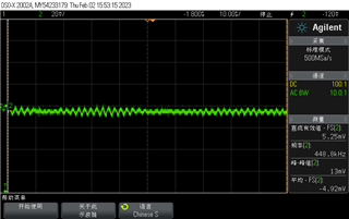
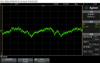
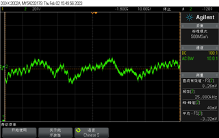
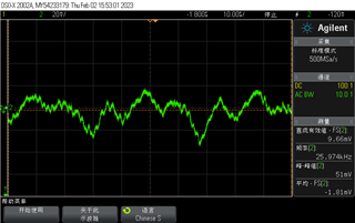
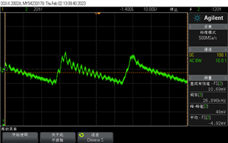
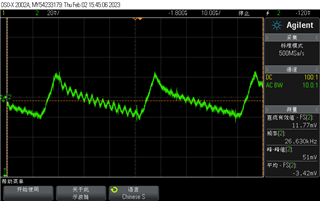
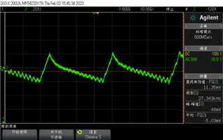
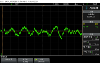
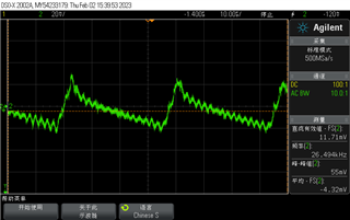
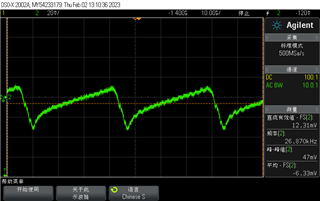
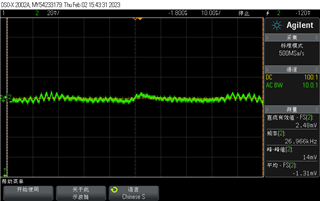
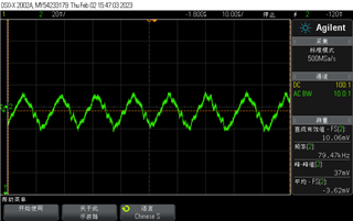
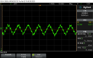
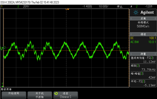
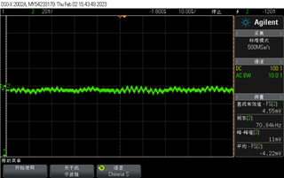
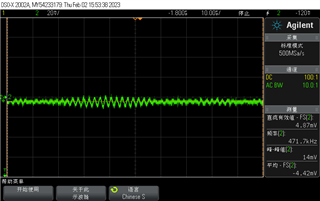
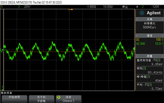
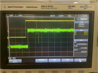
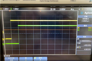
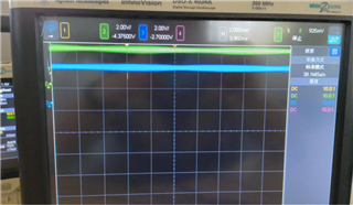
I would like to ask a question. After power-on, 28335 program does not work, at the moment, the power supply, crystal oscillator and power supply ripple are normal. then,  pull reset pin to a low level to force reset, but DSP still can not reset or  work; After power off and restart, DSP can work.

  • Is this a new design or an existing design in production?

    Can you share the scope waveform for power-up? I'd like to see 1.8v, 3.3v, X1/X2 and -XRS.

    Would you be willing to share the schematics with me privately? I don't need the complete schematics. I only need to see all the pins of the DSP.

  • power_5v:

    power_3.3v:

    power_1.9v:

    The power supply is TPS62040, which is done according to the circuit in the manual. The monitoring TPS3307 is also done according to the circuit given in the manual.

    This is the normal reset signal, the reset signal for both DSP.

    This is that both DSP are faulty after starting the machine, and neither DSP has reset signal:

    This is a DSP fault after startup. There is a reset signal, and there is no reset signal:

  • You have not answered the questions below:

    1. Is this a new design or an existing design in production?
    2. Would you be willing to share the schematics with me privately? I don't need the complete schematics. I only need to see all the pins of the DSP.

    Also please clarify if this post is the same as this post.

  • This is not a new design. It's about 10 years old.

    After the fault, all four pins of BOOT are high, 1.9V, 3.3V, RST and crystal oscillator are normal, but the CPU still does not work when a reset signal is given to RST again.Two DSPs have a TPS3307 reset, two DSPs have two reset signals; After failure, the two reset signals are GND.

    DSP1

    DSP2

    Reset

  • Hello, I would like to add some information. The problem occurred when the board card was newly produced and replaced on the device. The problem occurred after it had been used normally for about one month. The phenomenon is that it does not work occasionally after being powered on. It will be normal again when it is powered on. Therefore, it is doubtful whether it is possible in the process of replacement

  • Closing this post since it is a duplicate of this post.