This thread has been locked.

If you have a related question, please click the "Ask a related question" button in the top right corner. The newly created question will be automatically linked to this question.

TMS320F2800137: The bigger the ADC Clock, the faster the ADC sampling rate, the better the sampling results and real-time performance, why we need setting ADC frequency division table?

Part Number: TMS320F2800137

Hi Champs,

I am asking for my customer here.

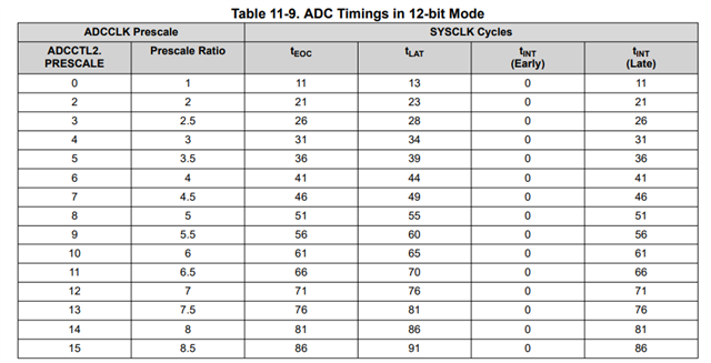
Please help to understand the frequency division setting basis of the ADC clock as below figure? How to choose the frequency division of ADC clock? What is the purpose of setting different ADC clocks?
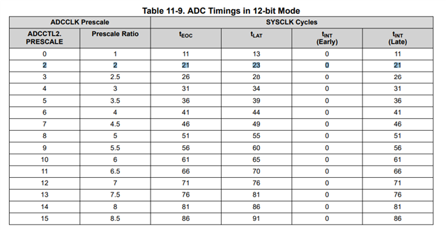
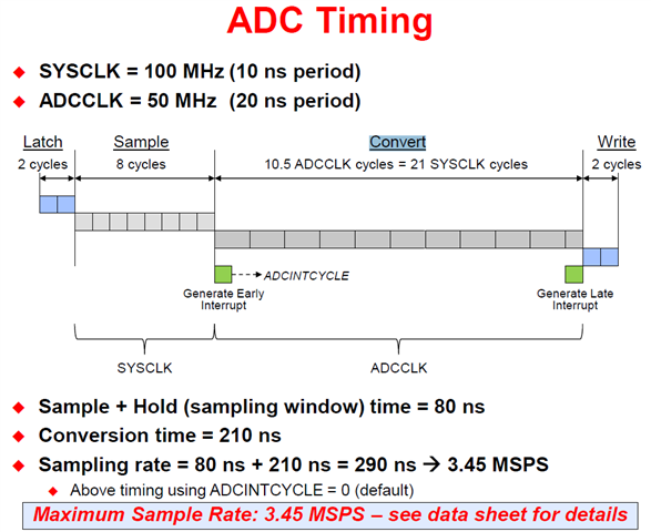
The ADC clock is related to ADC Timing. When the ADC Clock is smaller, the conversion time is longer, so the sampling rate is slower for Slow ADC. And judge from the below figure, 
So when the ADCCTL2. PRESCALE = 0, Prescale Ratio = 1, ADC Clock = Sysclk =120MHz >> 60MHz, the ADC conversion time Min is 11ADCCLKS, Right?

But we don't know the significance of setting ADC frequency division? Or what kind of ADC frequency division is applied in the application scenario. Could you give me an example to help understand.

Because from the ADC conversion time, The bigger the ADC Clock, the better, the faster the ADC sampling rate, the better the sampling results and real-time performance. Please help to understand the frequency division setting basis of the ADC clock? Thanks a lot!

  • Hi Teams,

    Or refer the Note, how to judge the an appropriate value for ADCCTL2.PRESCALE from different application scenarios? where basis for reference?

  • Hello Shaoxing,

    There are two different clocks used during the ADC sampling process:

    • Sample+Hold (Acquisition Window) - This uses SYSCLK, and is configured per SOC using the ACQPS parameter. The minimum acquisition window for the F280013x ADC is 75ns, but depending on the input driver requirements, this may need to be larger to ensure the sample cap has charged to an accurate level before starting conversion.
    • Conversion - This uses ADCCLK. ADCCLK is divided down from SYSCLK using the ADCCTL2.PRESCALE divider. The maximum speed of ADCCLK is 60MHz, so on F280013x, prescale of 0 is invalid and will not work. For most users, it is recommended to set PRESCALE=2 so that ADCCLK=60MHz when SYSCLK=120MHz. If for some reason there is a need to slow down the ADC conversion clock, that is also possible by setting PRESCALE to a higher value. This will not improve the performance of the ADC though, so the simple answer is to just set it to 2 unless there is a specific reason to do otherwise.

    In most cases, the value of ACQPS is what will determine the user's sample rate. Depending on the driver circuit design, the user should always calculate the required acquisition window duration before configuring ACQPS to ensure accurate conversions. For more, please refer to the ADC chapter in F280013x TRM under "Additional Information > Choosing an Acquisition Window Duration".

    Best regards,
    Ibukun

  • Hi lbukun,

    Totally understanding. But does setting the ADC frequency division have any significance?

    Like you said, we just provide the options # set PRESCALE=2 so that ADCCLK=60MHz when SYSCLK=120MHz. Why we need the below Table? Thanks.

  • The table is there for reference so that the user has a precise reference of the cycle counts involved when performing ADC conversions for any prescale setting configured - either to know when ADC results would be available, or say for instance, if the user triggers a burst of conversions across multiple channels, they can calculate exactly how long all the conversions take and when the ISR would be triggered/how many cycles to budget for the control loop.

    Note that the PRESCALE=0 row is not entirely invalid. It is possible that SYSCLK frequency is <= 60MHz and so the ADC can be set to use PRESCALE of 0.

    Ibukun

  • Hi lbukun,

    Got it, thanks.