- Ask a related questionWhat is a related question?A related question is a question created from another question. When the related question is created, it will be automatically linked to the original question.
This thread has been locked.
If you have a related question, please click the "Ask a related question" button in the top right corner. The newly created question will be automatically linked to this question.
Hi,
I have made a control card using TMS320F28379D MCU, I am trying to flash this board with LAUNCHPAD-XL280049 with XDS110 connection but i am not able to do this. I have tried many time but still unsuccessful.
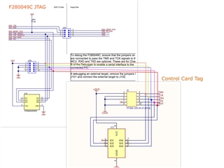
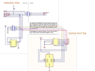
I have connected the TMS320F28379D pins TMS,TCLK,TDO,TDI and TRST pins with LAUNCHPAD-XL280049 same pins.
Observation found:
- TDO signal is high (no signal)
- TRSTn level - 1.4 V
Please find the schematic of our board.
Please find the connection on hardware
Please find the boot section of our schematic

I have mounted R128 and R129 but still it not flashing the controller.
I have tried to flash the board launchpad-xl28379d by launchpad280049 , it is successful for flashing but not happening with our control card , Please suggest appropriate way or tell us what mistake we are making?
Hi,
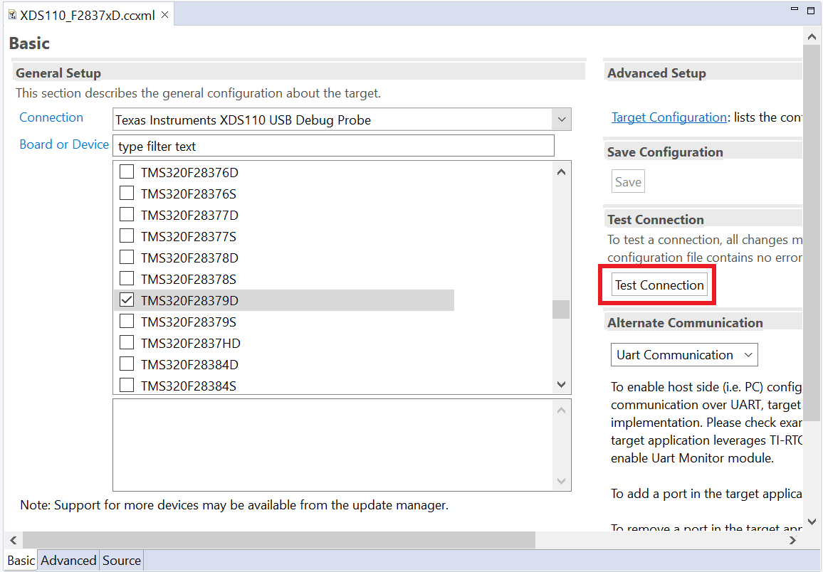
Could you please try testing connection with your target configuration in CCS? Please post the output log here
Best Regards,
Ben Collier
I have tried all the possible ccs target setting with xds110 but still it did not worked.
Did you find any mistake in schematic or can you please provide appropriate setting. We have to do it asap , otherwise our project will be in trouble. Can we please do a team meeting for this.
I am struggling with this from three days..kindly let me know your availability for the same.
Hi,
I am sorry to hear that. I do not have any availability this week, so let's try to solve this on this forum. Could you please post the output log from 'Test Connection' with your target configuration? The error log will be helpful in narrowing the possible problems.
I do not see anything obviously wrong with your schematic, but I am worried about signal integrity issues from the image you have sent me, since there are relatively long wires from the Launchpad to the controlCARD. If this really is the issue, we will see a certain message from the 'Test Connection' output log about scanning in something different that what was scanned out.
Without knowing this error message, there are many things that could be causing the issue. For example, your 2.2K Ohm pull-down resistor on TRST may need to be increased to 10kOhm, depending on the drive strength of the debug probe, but I do not know if that is really the issue without the Test Connection Error Message.
Also, is this a controlCARD purchased from TI, or is this a custom board? If it is a custom board, could you please provide a full schematic for you board?
Best Regards,
Ben Collier
Please find the schematic . This is custome control card made by us.this not from ti but we took reference from ti control card boardCCZ_F28379D_2 - Copy.pdf
Hi Vikas,
Thank you for providing your schematic. I do not see anything that is wrong with your schematic, but I noticed a couple things in the picture that might cause problems with the JTAG connection, as I mentioned above. Could you please post your output log from using the 'Test Connection' option on your target configuration (.ccxml) file in CCS, as shown below?

The output log will be helpful to figure out what is going wrong. Also, do you have access to an oscilloscope or a logic analyzer for further troubleshooting?
Best Regards,
Ben Collier
Dear Benjamin,
Thanks for taking time out. We're using XDS110 of LAUNCHXL-F280049C. Same XDS is able to communicate with LAUNCHXL-F28379D but not with our board. Below are some of our observations:
- Pull down on TRSTn: Both our control card and LAUNCHXL-F28379D have same pull-down resistor of 2.2K. In this case of launchpad voltage on this pin is ~3.1V but it is 1.4V with our control card.
- Pull down resistors on GPIO84 and GPIO72: These resistors are mounted and connected on LAUNCHXL-F28379D. We've tried both options with these resistors mounted and unmounted on the control card but not working in any case. Can you please suggest if pulldown resistors on these GPIOs are required or not.
- Signal integrity issues due to long wires: Almost same setup working when connecting LAUNCHXL-F28379D with XDS110 of other launchpad. We will check again with short wires.
- We have access to 2 channel oscilloscope and can see signals. Just for your information we checked TMS, TDO, TDI and TRSTn with TCK. One quick observation is that there was no pulses on TDO, it was high.
- Logs of test connection are below:
[Start: Texas Instruments XDS110 USB Debug Probe_0]
Execute the command:
%ccs_base%/common/uscif/dbgjtag -f %boarddatafile% -rv -o -S integrity
[Result]
-----[Print the board config pathname(s)]------------------------------------
C:\Users\ADMIN\AppData\Local\TEXASI~1\CCS\
ccs1210\0\0\BrdDat\testBoard.dat
-----[Print the reset-command software log-file]-----------------------------
This utility has selected a 100/110/510 class product.
This utility will load the adapter 'jioxds110.dll'.
The library build date was 'Sep 20 2022'.
The library build time was '12:28:44'.
The library package version is '9.9.0.00040'.
The library component version is '35.35.0.0'.
The controller does not use a programmable FPGA.
The controller has a version number of '5' (0x00000005).
The controller has an insertion length of '0' (0x00000000).
This utility will attempt to reset the controller.
This utility has successfully reset the controller.
-----[Print the reset-command hardware log-file]-----------------------------
The scan-path will be reset by toggling the JTAG TRST signal.
The controller is the XDS110 with USB interface.
The link from controller to target is direct (without cable).
The software is configured for XDS110 features.
The controller cannot monitor the value on the EMU[0] pin.
The controller cannot monitor the value on the EMU[1] pin.
The controller cannot control the timing on output pins.
The controller cannot control the timing on input pins.
The scan-path link-delay has been set to exactly '0' (0x0000).
-----[An error has occurred and this utility has aborted]--------------------
This error is generated by TI's USCIF driver or utilities.
The value is '-230' (0xffffff1a).
The title is 'SC_ERR_PATH_MEASURE'.
The explanation is:
The measured lengths of the JTAG IR and DR scan-paths are invalid.
This indicates that an error exists in the link-delay or scan-path.
[End: Texas Instruments XDS110 USB Debug Probe_0]
One more message that comes very frequently is:
[Start: Texas Instruments XDS110 USB Debug Probe_0]
Execute the command:
%ccs_base%/common/uscif/dbgjtag -f %boarddatafile% -rv -o -S integrity
[Result]
-----[Print the board config pathname(s)]------------------------------------
C:\Users\ADMIN\AppData\Local\TEXASI~1\CCS\
ccs1210\0\0\BrdDat\testBoard.dat
-----[Print the reset-command software log-file]-----------------------------
This utility has selected a 100/110/510 class product.
This utility will load the adapter 'jioxds110.dll'.
The library build date was 'Sep 20 2022'.
The library build time was '12:28:44'.
The library package version is '9.9.0.00040'.
The library component version is '35.35.0.0'.
The controller does not use a programmable FPGA.
The controller has a version number of '5' (0x00000005).
The controller has an insertion length of '0' (0x00000000).
This utility will attempt to reset the controller.
This utility has successfully reset the controller.
-----[Print the reset-command hardware log-file]-----------------------------
The scan-path will be reset by toggling the JTAG TRST signal.
The controller is the XDS110 with USB interface.
The link from controller to target is direct (without cable).
The software is configured for XDS110 features.
The controller cannot monitor the value on the EMU[0] pin.
The controller cannot monitor the value on the EMU[1] pin.
The controller cannot control the timing on output pins.
The controller cannot control the timing on input pins.
The scan-path link-delay has been set to exactly '0' (0x0000).
-----[An error has occurred and this utility has aborted]--------------------
This error is generated by TI's USCIF driver or utilities.
The value is '-233' (0xffffff17).
The title is 'SC_ERR_PATH_BROKEN'.
The explanation is:
The JTAG IR and DR scan-paths cannot circulate bits, they may be broken.
An attempt to scan the JTAG scan-path has failed.
The target's JTAG scan-path appears to be broken
with a stuck-at-ones or stuck-at-zero fault.
[End: Texas Instruments XDS110 USB Debug Probe_0]
Hi Benjamin, we tried with much shorter wires and below is the output log:
[Start: Texas Instruments XDS110 USB Debug Probe_0]
Execute the command:
%ccs_base%/common/uscif/dbgjtag -f %boarddatafile% -rv -o -S integrity
[Result]
-----[Print the board config pathname(s)]------------------------------------
C:\Users\ADMIN\AppData\Local\TEXASI~1\CCS\
ccs1210\0\0\BrdDat\testBoard.dat
-----[Print the reset-command software log-file]-----------------------------
This utility has selected a 100/110/510 class product.
This utility will load the adapter 'jioxds110.dll'.
The library build date was 'Sep 20 2022'.
The library build time was '12:28:44'.
The library package version is '9.9.0.00040'.
The library component version is '35.35.0.0'.
The controller does not use a programmable FPGA.
The controller has a version number of '5' (0x00000005).
The controller has an insertion length of '0' (0x00000000).
This utility will attempt to reset the controller.
This utility has successfully reset the controller.
-----[Print the reset-command hardware log-file]-----------------------------
The scan-path will be reset by toggling the JTAG TRST signal.
The controller is the XDS110 with USB interface.
The link from controller to target is direct (without cable).
The software is configured for XDS110 features.
The controller cannot monitor the value on the EMU[0] pin.
The controller cannot monitor the value on the EMU[1] pin.
The controller cannot control the timing on output pins.
The controller cannot control the timing on input pins.
The scan-path link-delay has been set to exactly '0' (0x0000).
-----[An error has occurred and this utility has aborted]--------------------
This error is generated by TI's USCIF driver or utilities.
The value is '-233' (0xffffff17).
The title is 'SC_ERR_PATH_BROKEN'.
The explanation is:
The JTAG IR and DR scan-paths cannot circulate bits, they may be broken.
An attempt to scan the JTAG scan-path has failed.
The target's JTAG scan-path appears to be broken
with a stuck-at-ones or stuck-at-zero fault.
[End: Texas Instruments XDS110 USB Debug Probe_0]
Please suggest how to proceed?
Hi Benjamin,
We are using the MCU from automotive grade (TMS320F28379DPTPQ). Changing TRSTn pull down to 10k didn't work but worked with 100K resistor
Now it can be connected with the XDS110 but another problem we are facing while flashing the MCU. It is giving the error for low power mode. logs are below.
(Error -1156 @ 0xB268)
Device may be operating in low-power mode. Do you want to bring it out of this mode? Choose 'Yes' to force the device to wake up and retry the operation. Choose 'No' to retry the operation without waking the device.
How can we make it out of the low power mode, is there anything we are missing in the schematic?
Also we were able to read the memory with UNIFLASH.
Hi Vikas,
I am glad to hear that you are now able to connect to the device. Could you please try putting the device in wait-boot mode by pulling GPIO72 high and pulling GPIO84 low as shown below?

Best Regards,
Ben Collier
Hi Benjamin,
We are this wait mode combination but still we are not able to flash the MCU , it is keep showing the error of the low power mode. but er are able to connect it and able to read the memory from uniflash tool. please provide the details what we are making mistakes.
We have connected the TRST,T MS,TCK,TDI and TDO pin of the mcu from th
 e lauchpad f280049.
Hi Vikas,
I would be curious if TRST is correctly being driven high by the XDS110. Could you try triggering oscilloscope captures when TRST goes below 2.5V to see if this happens while you are connected? Could you also try updating the firmware of the XDS110 with the instructions from this link: https://software-dl.ti.com/ccs/esd/documents/xdsdebugprobes/emu_xds110.html
Also, I am happy to continue helping you troubleshoot, but you may have an easier time with flashing your device if you purchase a standalone JTAG Debug Probe like the XDS100 (from Olimex or Blackhawk) or the standalone XDS110 (from TI.com). I am worried that there may be something about the XDS110 on the launchpad that was designed without consideration for connecting to other boards.
Best Regards,
Ben Collier
Dear Benjamin, thanks.
Thanks for your suggestion. We will buy the debug probe as you've suggested. For now, we've been able to flash the MCU. We did below things:
- Checked the supply lines of MCU on oscilloscope and all looked good.
- Still increased the CC limit of power supply from 100 mA to 1 A and it worked. Current consumption during flash operation is > 300 mA which we were not expecting and it was the problem as supply was limiting the current. But we did not see any glitch in the supply lines.x
- Still one potential problem is related to pull down resistor value on TRSTn. We're using 100k while the recommended is 2.2k or less. Not sure why debugger after debugger is connected, we don't get good value of voltage on TRSTn with 2.2k pulldown on our board. While the same debugger shows 3V while programming the launchpad with 2.2k pulldown. Only difference is of the MCU package: control card has HLQFP-176 (automotive grade) while launchpad has NFBGA-337.
- Are these parts different in terms of TRSTn?
- Will we face problem later for using 100k pulldown on TRSTn?
Hi Vikas,
I was surprised to see that you needed a 100k pulldown resistor to be able to connect. I think that the drive strength of the Launchpad's XDS110 is not very strong, since it was unable to drive TRST high when the resistor values were too low.
I would not be surprised if the 100k Ohm pulldown resistor still works when you try to flash your device with a new JTAG Debug Probe, but it would be better practice to use a 10k Ohm resistor if that works. The motivations for using a pulldown resistor on TRST is to keep the TRST pin in a known state while the device is running without a connected JTAG debug probe. If the value of TRST goes high while your application is running, perhaps due to noise, the application will stop as the device will think a JTAG debug probe has been connected. Essentially, smaller resistor values provide better protection against noise glitches than high resistor values, but the JTAG debug probe still needs to be able to drive TRST high to program the device.
The internal circuitry of the JTAG pins should be the same on different packages and between automotive and non-automotive.
Best Regards,
Ben Collier