This thread has been locked.

If you have a related question, please click the "Ask a related question" button in the top right corner. The newly created question will be automatically linked to this question.

C2000WARE-MOTORCONTROL-SDK: Motor control inverter design with TMDSHVMTRINSPIN and F280049C

Part Number: C2000WARE-MOTORCONTROL-SDK
Other Parts Discussed in Thread: TMDSHVMTRINSPIN, C2000WARE

Hi TI team,

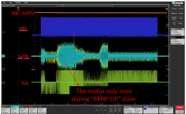
I'm debugging the motor control with TMDSHVMTRINSPIN in C2000Ware_MotorControl_SDK_4_00_00_00. My motor's rated parameters are: 320V, 38A, 3000rmps, 200Hz. Now I'm trying to run the motor with lab7. As my understanding, it should start with a constant current under forcedangle mode ro run the motor. After the motor can runs at a certain speed, then we can add the speed close loop by the command"motorVars.flagEnableForceAngle=0 ". I'm not sure whether my understanding is right or not. If so, how and where can I change the start up current? My motor's inertia is much larger than the kit's. As the following waveform shown, the motor cannot run with the orignal start up current(forced frequency 5Hz). But I didn't find how to increase this current. Would you please help on this? Looking forward to your reply. Thank you very much!   

Best regards,

Iris Liu

  • The DC bus voltage is too high for TMDSHVMTRINSPIN, the voltage must be lower than 450V if you didn't change the bulk capacitor and power module.

    The speed closed-loop is not disabled/enabled by using this motorVars.flagEnableForceAngle variable. The motorVars.flagEnableForceAngle is only for startup, the InstaSPIN-FOC will switch to closed-loop automatically. You may take a look at the lab user's guide and InstaSPIN User's guide for more details.

    You may refer to the lab guide to run the example labs, the guide at the folder below.

    \ti\c2000\C2000Ware_MotorControl_SDK_<version>\solutions\common\sensorless_foc\docs\labs

    There is no a variable to set the startup current in lab07 since lab07 implement the speed-closed loop.

    Having an incorrect Rs value (especially a value higher than the actual Rs) will make the start-up behave poorly. You might refer to chapter 14 "Managing Full Load at Startup, Low-Speed and Speed Reversal" in InstaSPIN-FOC and InstaSPIN-MOTION User's Guide

    https://www.ti.com/lit/spruhj1

    1. Enable stator Rs recalibration before startup
    2. Enable forced angle
    3. Make sure that the current ADC offset is calibrated.
  • Hi Yanming,

    Yes, I have redesigned the inverter and control board with higher voltage and the sample scale. I will have a try after the Rs recalibration and update the status here. Thanks for your suggestions.  

  • Hi Yanming,

    I have retested the motor parameters ID with lab5. As the following picture shows, the process is not running well. The motor only runs during the EST status "RAMP UP". The other picture is the identified parameters. It's highly apprectiated if you could give me some comments on this issue and identified parameters. Thanks for your reply!    


  • To identify the motor without any load, and try to tune the identification variables below according to the motor.

    #define USER_MOTOR_RES_EST_CURRENT     (2.0)                               // A - 10-30% of rated current of the motor

    #define USER_MOTOR_IND_EST_CURRENT     (-1.5)                             // A - 10-30% of rated current of the motor, just enough to enable rotation

    #define USER_MOTOR_MAX_CURRENT           (20.0)                               // A - 30~150% of rated current of the motor

    #define USER_MOTOR_FLUX_EST_FREQ_Hz     (40.0)                           // Hz - 10~30% rated frequency of the motor

    If the identification is still failed on your own board, you have to check if the current and voltage sensing signals are good enough for InstaSPIN-FOC, and the hardware parameters are set correctly.

  • Hi Yanming,

    I have tune the identification variables and retest under no load. The results are similar issues.

    1. Rs state: No current is set.   And how to set it?  

    2. Ramp up state: Current Shoot when change to next state. Why is like that?

    3. Rated Flux state: The motor stop running. So I increase the USER_MOTOR_FLUX_EXC_FREQ_Hz to 30Hz. But OCP(40A) happened when switch to Rated flux state.  

    4. Ls state: The motor didn't run and sway slightly at the first 10s(EST_LS_STATE_RAMPUP time is 10s). And then stop sway and no current. Under EST_LS_STATE_RAMPUP state, is the same current close loop as lab4 implemented at the first 10s? Or else?

    Here's the OCP waveforms with USER_MOTOR_FLUX_EXC_FREQ_Hz=30Hz, USER_MOTOR_RES_EST_CURRENT_A=10A, USER_MOTOR_IND_EST_CURRENT_A=-6A:

    The hardware has tested under lab4 and works well. BTW, can I step lab5 and start lab7 with the parameters from the motor vendor?  

  • 1. Rs state: No current is set.   And how to set it?  

    2. Ramp up state: Current Shoot when change to next state. Why is like that?

    Please provide the spec. of the motor and the user.h you used.

    3. Rated Flux state: The motor stop running. So I increase the USER_MOTOR_FLUX_EXC_FREQ_Hz to 30Hz. But OCP(40A) happened when switch to Rated flux state.  

    4. Ls state: The motor didn't run and sway slightly at the first 10s(EST_LS_STATE_RAMPUP time is 10s). And then stop sway and no current. Under EST_LS_STATE_RAMPUP state, is the same current close loop as lab4 implemented at the first 10s? Or else?

    Are you using your own board or TMDSHVMTRINSPIN for this? Any load is adding on the motor during this test?