Other Parts Discussed in Thread: C2000WARE
Hello,
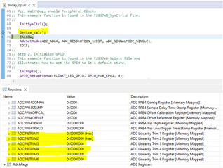
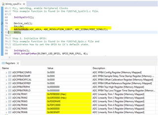
Regarding the ADC trims that need to be loaded every time the ADC mode and resolution changes, per the errata, I have three questions:
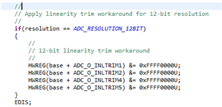
- Why for a 12bit resolution, the upper 16bits of INLTRIM1,2,4,5 are kept and the lower 16 bits are set to zero?
- Why INLTRIM3 and INLTRIM6 are kept the same?
Could someone explain to me a little bit more in details the way this work. The industry in which my application is used, require me to have a clear understand on the way it works for safety reasons.
- What does module reset mean in the following sentence from the TRM? If there is a DSP reset aren't the boot ROM repopulating the ADC trims registers?

Thank you.
Laurent