- Ask a related questionWhat is a related question?A related question is a question created from another question. When the related question is created, it will be automatically linked to the original question.
This thread has been locked.
If you have a related question, please click the "Ask a related question" button in the top right corner. The newly created question will be automatically linked to this question.
Hello
I have the same problem as the person in the linked post. I am getting a
The value is '-183' (0xffffff49).
The title is 'SC_ERR_CTL_CBL_BREAK_FAR'.
The explanation is:
The controller has detected a cable break far-from itself.
The user must connect the cable/pod to the target.
massage every time when I am trying to program my TMS320F2738D-Q1 chip.
When I try to verify the XDS100v2 I designed I get
[Start]
Execute the command:
%ccs_base%/common/uscif/dbgjtag -f %boarddatafile% -rv -o -F inform,logfile=yes -S pathlength -S integrity
[Result]
-----[Print the board config pathname(s)]------------------------------------
C:\Users\FALCEN~1\AppData\Local\TEXASI~1\
CCS\ccs1230\0\0\BrdDat\testBoard.dat
-----[Print the reset-command software log-file]-----------------------------
This utility has selected a 100/110/510 class product.
This utility will load the adapter 'jioserdesusb.dll'.
The library build date was 'Mar 10 2023'.
The library build time was '17:27:27'.
The library package version is '9.11.0.00128'.
The library component version is '35.35.0.0'.
The controller does not use a programmable FPGA.
The controller has a version number of '4' (0x00000004).
The controller has an insertion length of '0' (0x00000000).
This utility will attempt to reset the controller.
This utility has successfully reset the controller.
-----[Print the reset-command hardware log-file]-----------------------------
The scan-path will be reset by toggling the JTAG TRST signal.
The controller is the FTDI FT2232 with USB interface.
The link from controller to target is direct (without cable).
The software is configured for FTDI FT2232 features.
The controller cannot monitor the value on the EMU[0] pin.
The controller cannot monitor the value on the EMU[1] pin.
The controller cannot control the timing on output pins.
The controller cannot control the timing on input pins.
The scan-path link-delay has been set to exactly '0' (0x0000).
-----[The log-file for the JTAG TCLK output generated from the PLL]----------
There is no hardware for programming the JTAG TCLK frequency.
-----[Measure the source and frequency of the final JTAG TCLKR input]--------
There is no hardware for measuring the JTAG TCLK frequency.
-----[Perform the standard path-length test on the JTAG IR and DR]-----------
This path-length test uses blocks of 64 32-bit words.
The JTAG IR instruction path-length was not recorded.
-----[Perform the Integrity scan-test on the JTAG IR]------------------------
This test will use blocks of 64 32-bit words.
This test will be applied just once.
Do a test using 0xFFFFFFFF.
Scan tests: 1, skipped: 0, failed: 0
-----[An error has occurred and this utility has aborted]--------------------
This error is generated by TI's USCIF driver or utilities.
The value is '-183' (0xffffff49).
The title is 'SC_ERR_CTL_CBL_BREAK_FAR'.
The explanation is:
The controller has detected a cable break far-from itself.
The user must connect the cable/pod to the target.
[End]
the FTDI chips EEPROM is programmed with the xds100v2.xml provided by ti

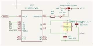
Raphael,
Do you have a standalone JTAG emulator available as well? I just want to make sure if we use that to connect, that is working OK, to rule out the device state, etc interfering with things.
Cable break error usually happens with very long cabling from the XDS to the target, since this is on your PCB I'm assuming that is not an issue. Can you comment on the trace length, co-location of the XDS100 relative to the C2000 MCU?
For debug, would it be possible to bypass the Isolators, to remove those from the equation?
Best,
Matthew
Thanks for the quick answer. Unfortunately I do not have a standalone JTAG from Ti I only have a ST link. I do not think that it is a Problem with the C2000 because when I connect a LAUNCHXL-F28379D and do not Connect the C2000 The error massage is
Error connecting to the target:
(Error -2131 @ 0x0)
Unable to access device register. Reset the device, and retry the operation. If error persists, confirm configuration, power-cycle the board, and/or try more reliable JTAG settings (e.g. lower TCLK).
(Emulation package 8.3.0.00003)
and that is what I would also expect when I also do not power my c2000 and only try to Programm it over the XDS100 but I get the same
The controller has detected a cable break far-from itself.
The user must connect the cable/pod to the target.
So I think that it is a problem with the XDS100 .
For trace length my board has the same form factor as the LAUNCHXL-F28379D so maybe 4-5cm
I agree, thanks for the detail here. Would it be possible to bypass the isolators to rule those out?
Best,
Matthew
Raphael,
Thanks of doing this, a cable break is a very specific error so I'm surprised that we are seeing it with an on-PCB soln like you have.
Can you look to see if this programmation file is any different(or gives different result) from what you have. This has a batch file, so you should just be able to execute the .bat vs using F/MPROG utility.
5468.xds100v2-FT_Prog_v2.2.zip
Best,
Matthew
Thanks for helping unfortunately I am getting the same error with this batch file as bevor.
Hi Raphael,
Your attached waveforms make it look like the right signals are coming from the FTDI chip, but nothing is coming from the C2000 part. Is it possible that your C2000 part has been damaged? Could you check voltages on power pins and reset pins? I would also be curious what your TRSTn JTAG signal looks like when you test connection to your device.
Best Regards,
Ben Collier
When I was trying to capture the TRSTn signal today I got an other error
[Start]
Execute the command:
%ccs_base%/common/uscif/dbgjtag -f %boarddatafile% -rv -o -F inform,logfile=yes -S pathlength -S integrity
[Result]
-----[Print the board config pathname(s)]------------------------------------
C:\Users\FALCEN~1\AppData\Local\TEXASI~1\
CCS\ccs1230\0\0\BrdDat\testBoard.dat
-----[Print the reset-command software log-file]-----------------------------
This utility has selected a 100/110/510 class product.
This utility will load the adapter 'jioserdesusb.dll'.
The library build date was 'Mar 10 2023'.
The library build time was '17:27:27'.
The library package version is '9.11.0.00128'.
The library component version is '35.35.0.0'.
The controller does not use a programmable FPGA.
The controller has a version number of '4' (0x00000004).
The controller has an insertion length of '0' (0x00000000).
This utility will attempt to reset the controller.
This utility has successfully reset the controller.
-----[Print the reset-command hardware log-file]-----------------------------
The scan-path will be reset by toggling the JTAG TRST signal.
The controller is the FTDI FT2232 with USB interface.
The link from controller to target is direct (without cable).
The software is configured for FTDI FT2232 features.
The controller cannot monitor the value on the EMU[0] pin.
The controller cannot monitor the value on the EMU[1] pin.
The controller cannot control the timing on output pins.
The controller cannot control the timing on input pins.
The scan-path link-delay has been set to exactly '0' (0x0000).
-----[The log-file for the JTAG TCLK output generated from the PLL]----------
There is no hardware for programming the JTAG TCLK frequency.
-----[Measure the source and frequency of the final JTAG TCLKR input]--------
There is no hardware for measuring the JTAG TCLK frequency.
-----[Perform the standard path-length test on the JTAG IR and DR]-----------
This path-length test uses blocks of 64 32-bit words.
The test for the JTAG IR instruction path-length failed.
The JTAG IR instruction scan-path is stuck-at-zero.
The test for the JTAG DR bypass path-length failed.
The JTAG DR bypass scan-path is stuck-at-zero.
-----[Perform the Integrity scan-test on the JTAG IR]------------------------
This test will use blocks of 64 32-bit words.
This test will be applied just once.
Do a test using 0xFFFFFFFF.
Test 1 Word 0: scanned out 0xFFFFFFFF and scanned in 0x00000000.
Test 1 Word 1: scanned out 0xFFFFFFFF and scanned in 0x00000000.
Test 1 Word 2: scanned out 0xFFFFFFFF and scanned in 0x00000000.
Test 1 Word 3: scanned out 0xFFFFFFFF and scanned in 0x00000000.
Test 1 Word 4: scanned out 0xFFFFFFFF and scanned in 0x00000000.
Test 1 Word 5: scanned out 0xFFFFFFFF and scanned in 0x00000000.
Test 1 Word 6: scanned out 0xFFFFFFFF and scanned in 0x00000000.
Test 1 Word 7: scanned out 0xFFFFFFFF and scanned in 0x00000000.
The details of the first 8 errors have been provided.
The utility will now report only the count of failed tests.
Scan tests: 1, skipped: 0, failed: 1
Do a test using 0x00000000.
Scan tests: 2, skipped: 0, failed: 1
Do a test using 0xFE03E0E2.
Scan tests: 3, skipped: 0, failed: 2
Do a test using 0x01FC1F1D.
Scan tests: 4, skipped: 0, failed: 3
Do a test using 0x5533CCAA.
Scan tests: 5, skipped: 0, failed: 4
Do a test using 0xAACC3355.
Scan tests: 6, skipped: 0, failed: 5
Some of the values were corrupted - 83.3 percent.
The JTAG IR Integrity scan-test has failed.
-----[Perform the Integrity scan-test on the JTAG DR]------------------------
This test will use blocks of 64 32-bit words.
This test will be applied just once.
Do a test using 0xFFFFFFFF.
Test 1 Word 0: scanned out 0xFFFFFFFF and scanned in 0x00000000.
Test 1 Word 1: scanned out 0xFFFFFFFF and scanned in 0x00000000.
Test 1 Word 2: scanned out 0xFFFFFFFF and scanned in 0x00000000.
Test 1 Word 3: scanned out 0xFFFFFFFF and scanned in 0x00000000.
Test 1 Word 4: scanned out 0xFFFFFFFF and scanned in 0x00000000.
Test 1 Word 5: scanned out 0xFFFFFFFF and scanned in 0x00000000.
Test 1 Word 6: scanned out 0xFFFFFFFF and scanned in 0x00000000.
Test 1 Word 7: scanned out 0xFFFFFFFF and scanned in 0x00000000.
The details of the first 8 errors have been provided.
The utility will now report only the count of failed tests.
Scan tests: 1, skipped: 0, failed: 1
Do a test using 0x00000000.
Scan tests: 2, skipped: 0, failed: 1
Do a test using 0xFE03E0E2.
Scan tests: 3, skipped: 0, failed: 2
Do a test using 0x01FC1F1D.
Scan tests: 4, skipped: 0, failed: 3
Do a test using 0x5533CCAA.
Scan tests: 5, skipped: 0, failed: 4
Do a test using 0xAACC3355.
Scan tests: 6, skipped: 0, failed: 5
Some of the values were corrupted - 83.3 percent.
The JTAG DR Integrity scan-test has failed.
[End]
so I think now the XDS100v2 works but the Chip dose not Is there a way to check what is wrong ? or do I have an error in my schematic? and my LED on XRS_N in glowing unless I try to program it then it goes out and stays out even If I reset the chip.
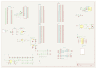
Raphael,
Are you still able to provide an oscilloscope screenshot of what your TRSTn signal looks like when you test connection or try to connect to the C2000 device?
Also, I do not think this Conn_ARM_JTAG_SWD_10 part was included in your last schematic screenshots. What is this part being used for and where is this RESET signal coming from?
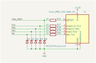
Also, it is good to see that the LED on XRSn is glowing, but could you also monitor the XRSn pin with an oscilloscope? I would be curious to see if it is always high, or if it is pulsing low every 50 ms or so.
Best Regards,
Ben Collier
Ben,
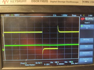
the yellow line is the TRSTn signal and the green is the ERRORSTS and sorry in my last post I meant that my LED is on ERRORSTS but the XRSn in constant 600mV. Sometimes my ERRORSTS signal is 1.2V sometime 400mV.
[Start]
Execute the command:
%ccs_base%/common/uscif/dbgjtag -f %boarddatafile% -rv -o -F inform,logfile=yes -S pathlength -S integrity
[Result]
-----[Print the board config pathname(s)]------------------------------------
C:\Users\FALCEN~1\AppData\Local\TEXASI~1\
CCS\ccs1230\0\0\BrdDat\testBoard.dat
-----[Print the reset-command software log-file]-----------------------------
This utility has selected a 100/110/510 class product.
This utility will load the adapter 'jioserdesusb.dll'.
The library build date was 'Mar 10 2023'.
The library build time was '17:27:27'.
The library package version is '9.11.0.00128'.
The library component version is '35.35.0.0'.
The controller does not use a programmable FPGA.
The controller has a version number of '4' (0x00000004).
The controller has an insertion length of '0' (0x00000000).
This utility will attempt to reset the controller.
This utility has successfully reset the controller.
-----[Print the reset-command hardware log-file]-----------------------------
The scan-path will be reset by toggling the JTAG TRST signal.
The controller is the FTDI FT2232 with USB interface.
The link from controller to target is direct (without cable).
The software is configured for FTDI FT2232 features.
The controller cannot monitor the value on the EMU[0] pin.
The controller cannot monitor the value on the EMU[1] pin.
The controller cannot control the timing on output pins.
The controller cannot control the timing on input pins.
The scan-path link-delay has been set to exactly '0' (0x0000).
-----[The log-file for the JTAG TCLK output generated from the PLL]----------
There is no hardware for programming the JTAG TCLK frequency.
-----[Measure the source and frequency of the final JTAG TCLKR input]--------
There is no hardware for measuring the JTAG TCLK frequency.
-----[Perform the standard path-length test on the JTAG IR and DR]-----------
This path-length test uses blocks of 64 32-bit words.
The test for the JTAG IR instruction path-length failed.
The JTAG IR instruction scan-path is stuck-at-ones.
The test for the JTAG DR bypass path-length failed.
The JTAG DR bypass scan-path is stuck-at-ones.
-----[Perform the Integrity scan-test on the JTAG IR]------------------------
This test will use blocks of 64 32-bit words.
This test will be applied just once.
Do a test using 0xFFFFFFFF.
Scan tests: 1, skipped: 0, failed: 0
Do a test using 0x00000000.
Test 2 Word 0: scanned out 0x00000000 and scanned in 0xFFFFFFFF.
Test 2 Word 1: scanned out 0x00000000 and scanned in 0xFFFFFFFF.
Test 2 Word 2: scanned out 0x00000000 and scanned in 0xFFFFFFFF.
Test 2 Word 3: scanned out 0x00000000 and scanned in 0xFFFFFFFF.
Test 2 Word 4: scanned out 0x00000000 and scanned in 0xFFFFFFFF.
Test 2 Word 5: scanned out 0x00000000 and scanned in 0xFFFFFFFF.
Test 2 Word 6: scanned out 0x00000000 and scanned in 0xFFFFFFFF.
Test 2 Word 7: scanned out 0x00000000 and scanned in 0xFFFFFFFF.
The details of the first 8 errors have been provided.
The utility will now report only the count of failed tests.
Scan tests: 2, skipped: 0, failed: 1
Do a test using 0xFE03E0E2.
Scan tests: 3, skipped: 0, failed: 2
Do a test using 0x01FC1F1D.
Scan tests: 4, skipped: 0, failed: 3
Do a test using 0x5533CCAA.
Scan tests: 5, skipped: 0, failed: 4
Do a test using 0xAACC3355.
Scan tests: 6, skipped: 0, failed: 5
Some of the values were corrupted - 83.3 percent.
The JTAG IR Integrity scan-test has failed.
-----[Perform the Integrity scan-test on the JTAG DR]------------------------
This test will use blocks of 64 32-bit words.
This test will be applied just once.
Do a test using 0xFFFFFFFF.
Scan tests: 1, skipped: 0, failed: 0
Do a test using 0x00000000.
Test 2 Word 0: scanned out 0x00000000 and scanned in 0xFFFFFFFF.
Test 2 Word 1: scanned out 0x00000000 and scanned in 0xFFFFFFFF.
Test 2 Word 2: scanned out 0x00000000 and scanned in 0xFFFFFFFF.
Test 2 Word 3: scanned out 0x00000000 and scanned in 0xFFFFFFFF.
Test 2 Word 4: scanned out 0x00000000 and scanned in 0xFFFFFFFF.
Test 2 Word 5: scanned out 0x00000000 and scanned in 0xFFFFFFFF.
Test 2 Word 6: scanned out 0x00000000 and scanned in 0xFFFFFFFF.
Test 2 Word 7: scanned out 0x00000000 and scanned in 0xFFFFFFFF.
The details of the first 8 errors have been provided.
The utility will now report only the count of failed tests.
Scan tests: 2, skipped: 0, failed: 1
Do a test using 0xFE03E0E2.
Scan tests: 3, skipped: 0, failed: 2
Do a test using 0x01FC1F1D.
Scan tests: 4, skipped: 0, failed: 3
Do a test using 0x5533CCAA.
Scan tests: 5, skipped: 0, failed: 4
Do a test using 0xAACC3355.
Scan tests: 6, skipped: 0, failed: 5
Some of the values were corrupted - 83.3 percent.
The JTAG DR Integrity scan-test has failed.
[End]
it now says Test2 instead of Test 1 what is the difference ?
The Conn_ARM_JTAG_SWD_10 was a solution for an other programer but the chip is not supportend by openocd so it is not populated at the moment
Hi,
Test 2 is referring to the first IR test that is failing. Since the TDO is always high, it passed Test 1 which used 0xFFFFFFFF as a test word. Last time, test 1 passed for some reason, so TDO was likely stuck low instead of stuck high.
From your oscilloscope screenshots, it looks like TRSTn is sitting around 1V. Is that the case, or am I misreading the settings from the screen? Also, about the ERRORSTS pin, have you checked that the correct voltages have been applied to all of your devices ground and power pins? Could you also please check the behavior on the XRS pin?
Best Regards,
Ben Collier
Hi in the last picture the Voltage was set ti 1V/dev so the TRSTn is 0V or 3.2V.
So I measured the supply voltages and they lock ok with 3.2V and 1.2V
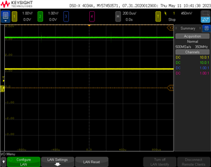
I also measured the Errorsts and XRS signals
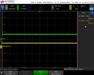
what Voltages would be ok for this signals?
Hi,
If the device has not been programmed before, we would expect the XRSn pin to be around 3.3V and occasionally pulsing low and for the ERRORSTS pin to be low. I will have to look into what could be causing the behavior seen in your oscilloscope screenshots.
Best Regards,
Ben Collier
Hi,
Could you try forcing TRSTn high with a pullup resistor? I would be curious if that changes the behavior at all. Otherwise I think the next step would be to try swapping out the C2000 device.
Best Regards,
Ben Collier