This thread has been locked.

If you have a related question, please click the "Ask a related question" button in the top right corner. The newly created question will be automatically linked to this question.

TMS320F28062: QEPSTS[QDF] toggle

Part Number: TMS320F28062

Hi Team,

There's an issue from the customer need your help:

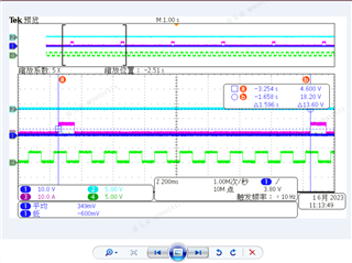
 the phase of the input quadrature signal QA is ahead of the phase of QB by 90°, and remains unchanged. Why does QEPSTS[QDF] toggling?

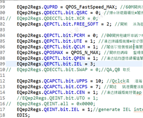
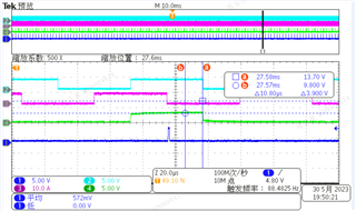
The order in the figure is: QB, QA, index signal and index flag (the index flag is obtained by detecting QFLAG[IEL] using GPIO flipping).

Could you help check this case?

Thanks & Regards,

Ben

  • Hi Ben,

    I have a few questions.

    1. How many quadrature cycles are you testing and this is happening for? Is this happening throughout the use of the EQEP?

    2. What does the system look like? Is this happening on a custom board or one of our EVMs?

    3. Is the customer able to graph the QEPSTS[QDF] bit with respect to the quadrature inputs?

    Regards,

    Peter

  • Hi Peter,

     1. I test many quadrature cycles, but the input quadrature signal is simulated by epwm, and the state register of eqep indicating the direction is changing during the whole process.

    2.This is an input of quadrature QA, QB and index signals in the eqep module of the DSP chip, and then observe the direction after passing through the decoding module; it happened on my company's self-made board, but I don't think it will affect it, because what I measured is Input chip side signal.

    3.Quadrature input QEPSTS[QDF] I think the change is with the QA electric frequency edge, but my program setting is a quadrature module, so it is very strange.

    Best Regards,

    Ben

  • Hi Ben,

    Thank you for the detailed information. It seems strange that this is happening. Can you try enabling input qualification for the QA, QB, and index signals, this will add 3-6 clock cycle delay to inputs but we can see if the QEPSTS[QDF] toggling may be a result of noisy GPIO inputs

    Regards,
    Peter

  • Hi Peter,

    It seems not working.

    Best Regards,

    Ben

  • Hi Ben,

    What is the behavior when QEPCTL[IEL] = 00, opposed to 11? This bit should be ignored when POSCTR is configured to reset on index market, PCRM = 00, but I'm interested in seeing what effect this might have. Otherwise I don't see any issues with the eQEP configuration. 

    Are you making sure that the index event is gated to the QEPB input throughout device operation? 

    Would you be able to get a oscilloscope output of QEPSTS[QDF] with respect to QEP inputs and index events, it will help to be able to see another graph of the issue.

    Regards,

    Peter

  • Hi Peter,

    What is the behavior when QEPCTL[IEL] = 00,

     It is the same phenomenon as QEPCTL[IEL] = 03, this is indeed different from the description in the manual.

    Are you making sure that the index event is gated to the QEPB input throughout device operation? 

    It can be guaranteed that the EQEB input dsp, but the EQEB input is not given by the encoder, it is an epwm analog input.

    Would you be able to get a oscilloscope output of QEPSTS[QDF] with respect to QEP inputs and index events, it will help to be able to see another graph of the issue.

    As shown below, the green line is the QEPSTS[QDF] waveform output, and the pink line index signal.

    Best Regards,

    Ben

  • Hi Ben,

    The repeated pattern on the QDF waveform indicates that this is not due to any glitches in the signal and is instead a result of the configuration. Can you provide the EPWM configuration used to produce the PWM inputs into the QA, QB, and QI?

    Is the customer able to provide some sample example for which I can run on my own hardware?

    Regards,

    Peter