This thread has been locked.

If you have a related question, please click the "Ask a related question" button in the top right corner. The newly created question will be automatically linked to this question.

TIDM-02002: Resetting CTRIPH/CTRIPL twice within a PWM cycle

Part Number: TIDM-02002
Other Parts Discussed in Thread: TMS320F28377D, TMS320F280049

Hi, here I am again with a new question regarding the CMPSS and EPWM interactions. I have solved most of the problems, except for the last (and bigger) one.

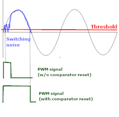
In the TIDM-02002 project, a synchronous rectification scheme has been implemented. Basically a current signal is fed to a comparator, and when it changes sign, the high side or low side PWM is shut down to simulate a diode behavior. When the current goes negative, the high side PWM is shut down; when the current goes positive, the low side PWM is shut down. In the application note (TIDUEG2C) there is a diagram that describes that:

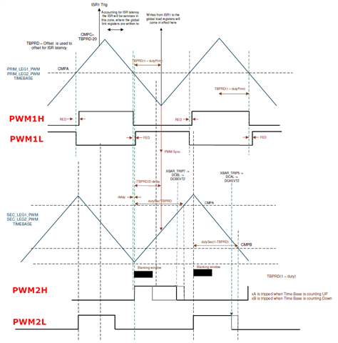
I've added the captions PWMxx for more clarity.

XBAR_TRIP7 is connected to CMPSS2 CTRIPH and it is used to shut down PWM2H, while XBAR_TRIP5 is connected to CMPSS2 CTRIPL and it is used to shut down PWM2L. The CTRIPx signals are latched, and in order for this to work it is necessary to reset the latches at two different times within each PWM cycle: CTRIPH has to be reset during the rising PWM edge, and CTRIPL has to be reset during the falling PWM edge. Otherwise one of the two signals would trip immediately (imagine the current as a sinusoidal signal synchronized with the PWM). And this is exactly what I'm seeing when I run the code.

Each CMPSS module is connected to a single EPWMSYNCPER signal, as shown in the technical reference:

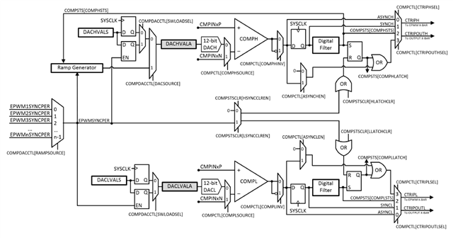
Therefore, unless you can generate two EPWMSYNCPER pulses within each PWM cycle (how?), both CTRIPx signals will be reset at the same time. This is exactly what I'm seeing running the code.

The original TIDM-02002 code was implemented on a TMS320F280049 MCU and had a single feature that is not present in the TMS320F28377D MCU (which I'm currently using), namely the possibility to use the EPWMBLANK signal to reset the CMPSS and to keep it reset for a certain time, in order to filter spurious signals close to the PWM switching. On the first figure you can see the two blanking periods (black rectangles) at the beginning of the PWM2L/PWM2H cycles.

Perhaps is this EPWMBLANK signal that can be generated twice within a cycle? How can I obtain the same result with 377D?

At the moment the only idea I have is to connect the current signal to two different comparators, using the CTRIPH of one of them and the CTRIPL of the other, in order to be able to use two different EPWMSYNCPER signals to reset each of them. But it seems quite a convoluted solution.

Thank you!

L.

  • L.,

    I see a few options.

    1. As you said use two different comparators that are not a CMPSSxH/L pair.
    2. Use the CMPSS's filter for the first filtering event, and use the ePWM's DC module's event filter for the second. The DC sub-module can be reset multiple times by a verity of sources at a time of your choosing, But there is only one instance of the filter per ePWM module. This means it cannot filter two different CMPSS inputs(without being reconfigured between each trip event) even if they are a H/L pair.- You could try using an ISR to reconfigure the DC filer, but I don't think this is an effective solution.
      1. *i'm not 100% confident in this method, but i don't see why it wouldn't work* 
    3. Move to a F2838x class of device which, is very similar to F28379D, but has the enhancements as seen on F28004x. https://www.ti.com/product/TMS320F28388 
      1. you can look at https://www.ti.com/lit/spru566 for some of the finer module type differences and which type was used on each C2000 device.

    Regards,
    Cody  

  • Thank you Cody. I've thought about the interrupt solution myself, but at the end I've used two different comparators. Moreover, I've verified experimentally that it is quite impossible to avoid the blanking functionality for this application. The 28377D provides the EPWMBLANK signal, but just for the EPWM module itself; the comparators are not held in reset during the blanking, therefore they can still trip during this period. To avoid that, I've advanced the EPWMSYNCPER signals to reset the comparators at the end of the blanking periods. Of course this required to use also two EPWM modules, since each one of them can generate only one EPWMSYNCPER pulse for each cycle.

    The solution is very inelegant, but fortunately I have several spare resources.

    Thank you for the hint on the F2838x family, I've never used it! In particular the 28384D seems pin-to-pin compatible with the 28377D, at least at a first glance. I don't think we can switch processors in this phase, but this will definitely come in handy in the future.

    L.

  • L.,

    This is not an elegant solution, but I am glad you were able to make it work. F28388D was designed to be Pin-to-Pin with a few minor PCB changes. Here should be a helpful guide when you potentially decide to move between the two families. https://www.ti.com/lit/pdf/spracq1 

    The 28377D provides the EPWMBLANK signal, but just for the EPWM module itself; the comparators are not held in reset during the blanking, therefore they can still trip during this period. 

    The comparator will trip during that time, but this shouldn't matter if the ePWM's filter is setup. I had assumed you were using the CMPSS output to trip the ePWM, are you using the CMPSS output directly for another purpose? If you are only tripping the ePWM signal with the output, then I believe this is not an issue as the filter in the PWM would keep the output from changing. Perhaps I am missing something though.


    Regards,
    Cody 

  • The comparator will trip during that time, but this shouldn't matter if the ePWM's filter is setup. I had assumed you were using the CMPSS output to trip the ePWM, are you using the CMPSS output directly for another purpose? If you are only tripping the ePWM signal with the output, then I believe this is not an issue as the filter in the PWM would keep the output from changing. Perhaps I am missing something though.

    I am using the blanking to filter out switching noise that is present at the beginning of the PWM cycle, and will wrongly trip the comparator. I've made an ugly sketch to describe that:

    In the first case I don't reset the comparator trip, and therefore as soon as the PWM blanking ends, the PWM output is shut down.

    In the second case I reset the comparator trip when the blanking ends, and therefore the comparator trips where it is supposed to (near to the end of the cycle).

    L.

  • Ah, this is because the signals is  tripping on both the low and high limit, I understand now.


    Regards,
    Cody