This thread has been locked.

If you have a related question, please click the "Ask a related question" button in the top right corner. The newly created question will be automatically linked to this question.

TMDSHVMTRPFCKIT: TMS320F28035

Part Number: TMDSHVMTRPFCKIT

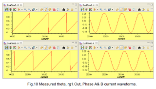
I have designed my own PCB similar to the TMDSHVMTRPFCKIT using the F28035 microcontroller.  I'm working through the levels in HVACI_Sensored but I'm stuck with an issue that I can't resolve on Level3b.  The "Sensored Field Oriented Control of 3-Phase Induction Motors" manual mentions that "ElecTheta and Out are of a Saw-Tooth wave shape and have the same period" as shown in the figure below.

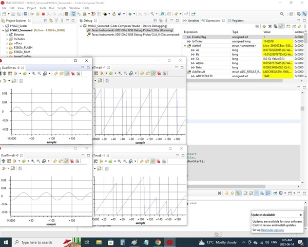
My "rg1.Out and speed1.ElecTheta curves look like the following:

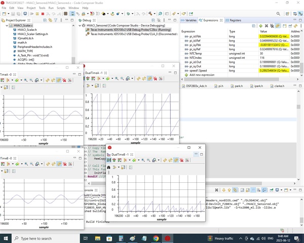
There is some issue with the speed1.ElecTheta curve.  The speed1.Speed signal seems to be working correctly in the watch window.  

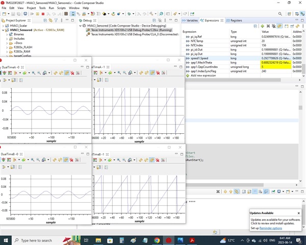
I think the issue has something to do with the QEP index signal.  When I spin the motor by hand, the qep1.QebCountIndex will increment from 4093, 4094, 0, 1, 2 and not increment any further. 

Does anybody have any insight into what may be causing the discrepancy? 

  • Did you change the parameters for the QEP module according to the encoder of the motor you used?

    // Initialize QEP module
    qep1.LineEncoder = 2048;
    qep1.MechScaler = _IQ30(0.25/qep1.LineEncoder);
    qep1.PolePairs = POLES/2;
    qep1.CalibratedAngle = 0;
    QEP_INIT_MACRO(1,qep1)

  • The only parameter I changed is 
    qep1.LineEncoder = 1024;

    I didn't check the number of pole pairs but I'm assuming it's a 4 pole motor since the rated speed is 1750RPM.

  • I added some shielding to my encoder signals and it improved the performance of the speed1.ElecTheta curve.  I have a feeling noise is causing false index signals. I'm going to try to integrate a Low Pass Filter to filter out some of the higher frequency noise.


  • I added a Low Pass Filter to the Encoder Index Signal and it improved the speed1.ElecTheta signal a lot more.  It looks almost as it should right now.  The only issue is that the speed1.ElecTheta signal "walks away" from the rg1.Out signal.  I'm assuming if the Index had some false index signals due to noise, it's likely the A and B signals have some false positives due to noise as well.  I'm going to add Low Pass Filters to A, B signals to help stabilize speed1.ElecTheta relative to rg1.Out.

  • You may try to configure the GPIO Input Qualification for QEP inputs as well. And need to do the index calibration to synchronize the angle between the RG and QEP modules.

  • I have added Low Pass Filters to A, B, and Index signals but the speed1.ElecTheta signal is still moving relative to rg1.Out on each oscilloscope refresh.  

    Please help me to understand these two charts... Since Speed1.Speed signal is always lagging SpeedRef due to slip, wouldn't Speed1.ElecTheta always move away from rg1.Out on each oscilloscope refresh?  I would assume this this movement is normal in an Open Loop system...

  • If the delat is a fixed value, yes, that could be fine.