This thread has been locked.

If you have a related question, please click the "Ask a related question" button in the top right corner. The newly created question will be automatically linked to this question.

TMS320F280041C: Control ePWM outputs based on other ePWM on and off events

Part Number: TMS320F280041
Other Parts Discussed in Thread: C2000WARE

Hi, 

I am implementing control for phase shifted full bridge converter with TMS320F280041 microcontroller. 
Power is controlled with EPWM1-EPWM4 phase shift. EPWM1 and EPWM4 are set in up-down mode and linked (EPWM1 sync out is used as EPWM4 sync in and phase controlled with TBPHS registers). Freq is 100kHz and duty 50%. Phase shift is in range [1; 0,5] (epwm1 lags after epwm4). Control loop frequency is 10kHz


This is working fine for me.

However, I am trying to implement synchronous rectifier control on EPM7 with usage of EPWM1 and EPM4 output OFF and ON events, similar like described with this topic:

https://e2e.ti.com/support/microcontrollers/c2000-microcontrollers-group/c2000/f/c2000-microcontrollers-forum/1158329/tms320f280048-q1-how-to-obtain-sr-waveforms-by-monitoring-other-epwm-channels-on-and-off-edges?tisearch=e2e-sitesearch&keymatch=synchronize%252520rectifier#

I am using T1 event to do that, the idea is:

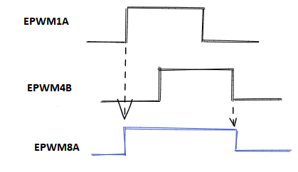
EPWM1: up-down mode, turn ON at CMPA up, turn OFF on CMPA down

EPWM4: up-down mode, turn ON at CMPA up, turn OFF on CMPA down, with phase shift in relation to EPWM1, CMPB-equal to CMPA is sync out for EPWM7 

EPWM7: up-down mode, as default set as EPWM1, but sync in from EPWM4 used as T1 event, so output is controlled with T1 and CMPA  events

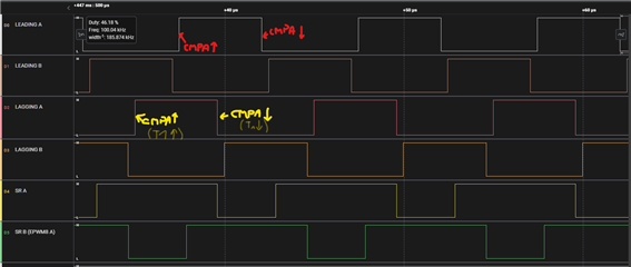
As I see, that logic of T1 is related to phase shift. When phase shift is greater than 0.75, then my event for controlling EPWM7 output is T1D, below 0.75 this event changes to T1U.
So with that I must change "on the fly" configuration of action qualifier for EPWM7.

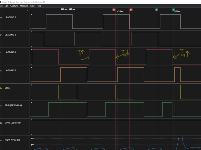
The problem is that, when I change this configuration when phase shift is 0.75 (which I do with checking TBPRD and TBPHS registers and their relation), then it looks like that sometimes it is too soon - 
action qualifier configuration was changed so it reacts to T1U instead of T1D and this is ruining desired PWM waveform.

Could you help me investigate and understand this issue? I will update this topic with code and images later if needed.

I would like to stay with T1 event approach as I am using digital compare module with CMPSS for protection 

  • Hi Dawid:

    Could you clarify this statement:

    "CMPB-equal to CMPA is sync out for EPWM7"

    There is no configuration to generate a sync out pulse on CMPA==CMPB. Is this what you meant?

    Is EPWM7 synchronized with EPWM1? What is the sync in source for EPWM7?

    Thank you,

    Luke

  • This is a complex configuration. If you could also send a scope shot of the waveform you're seeing, a diagram or description of the desired waveform, and list all of the settings that are being changed during run-time that would be helpful to resolve this issue.

  • Hi Luke,

    Sorry for late response, I had a problems with posting anything.

    "CMPB-equal to CMPA is sync out for EPWM7" it means that CMPB of EPWM4 has the same value as CMPA of EPWM4, and CMPB is sync out source for EPWM7.

    Below is my code configuration of relevant settings. Actually descibed configuration changed a little bit: I needed to implement some delay on synchronous rectifier, so it was done with rising edge deadtime on EPWM7A and EPWM8A output.


    Here is a waveform which I want to achieve - example for MODE 2


    And here is my situation with waveforms:

    Above phase shift is more than 0.75, so I am switching SR according to my initial configuration of action qualifiers for EPWM7 and EPWM8.

    But here is a problem:


    Falling edge of EPWM4 becomes my T1 up event before I am able to switch my configuration of action qualifiers.

    I tried many configurations of register shadowing or synchronization but I don't understand why it happens in the first place.

    Any thoughts?

    Best regards
    Dawid

    Fullscreen
    1
    2
    3
    4
    5
    6
    7
    8
    9
    10
    11
    12
    13
    14
    15
    16
    17
    18
    19
    20
    21
    /* EPWM1 setting (master): */
    EPwm1Regs.TBCTL.bit.CLKDIV = 0;
    EPwm1Regs.TBCTL.bit.HSPCLKDIV = 0;
    EPwm1Regs.TBPHS.bit.TBPHS = 0; // set Phase register to zero
    EPwm1Regs.TBCTL.bit.CTRMODE = TB_COUNT_UPDOWN; // symmetrical mode
    EPwm1Regs.TBCTL.bit.PHSEN = TB_DISABLE; // master module
    EPwm1Regs.TBCTL.bit.PRDLD = TB_SHADOW;
    EPwm1Regs.CMPCTL.bit.SHDWAMODE = CC_SHADOW;
    EPwm1Regs.CMPCTL.bit.SHDWBMODE = CC_SHADOW;
    EPwm1Regs.CMPCTL.bit.LOADAMODE = CC_CTR_ZERO_PRD; // load on CTR=Zero and Prd
    EPwm1Regs.CMPCTL.bit.LOADBMODE = CC_CTR_ZERO_PRD; // load on CTR=Zero and Prd
    EPwm1Regs.AQCTLA.bit.CAU = AQ_SET;
    EPwm1Regs.AQCTLA.bit.CAD = AQ_CLEAR;
    EPwm1Regs.AQCTLA.bit.PRD = AQ_NO_ACTION;
    EPwm1Regs.AQCTLA.bit.ZRO = AQ_NO_ACTION;
    EPwm1Regs.DBCTL.bit.OUT_MODE = DB_FULL_ENABLE; // enable Dead-band module
    EPwm1Regs.DBCTL.bit.POLSEL = DB_ACTV_HIC; // active Hi complementary
    EPwm1Regs.TZCTL.bit.TZA = TZ_NO_CHANGE;
    EPwm1Regs.TZCTL.bit.TZB = TZ_NO_CHANGE;
    EPwm1Regs.ETSEL.bit.INTSEL = ET_CTR_ZERO;
    XXXXXXXXXXXXXXXXXXXXXXXXXXXXXXXXXXXXXXXXXXXXXXXXXX

  • Hi Dawid,

    Have you tried using global load? This would ensure that your updated action qualifer settings for EPWM7 and new phase shift for EPWM4 are both loaded at EPWM TBCTR = 0.

    Another option that may be easier to implement is to use the CLB to generate your desired EPWM7 output. You could use the FSM in the CLB to trigger a rising edge on EPWM7 output on any rising edge of EPWM1, and a falling edge of EPWM7 output on any rising edge of EPWM4. This may be more reliable than changing your action qualifer settings for EPWM7 on the fly.

    Thank you,

    Luke

  • Hi

    I tried to set global load, but it doesn't help. Here is my configuration:

    Fullscreen
    1
    2
    3
    4
    5
    6
    7
    8
    9
    10
    11
    12
    13
    14
    15
    16
    17
    18
    19
    20
    21
    /* global load setting */
    // Sync source ePWM1 settings
    EPWM_enableGlobalLoadRegisters(EPWM1_BASE, EPWM_GL_REGISTER_CMPA_CMPAHR|EPWM_GL_REGISTER_CMPB_CMPBHR|
    EPWM_GL_REGISTER_AQCTLA_AQCTLA2);
    EPWM_setGlobalLoadTrigger(EPWM1_BASE, EPWM_GL_LOAD_PULSE_CNTR_PERIOD);
    EPWM_enableGlobalLoadOneShotMode(EPWM1_BASE);
    EPWM_enableGlobalLoad(EPWM1_BASE);
    // Sync receiver ePWM4 settings
    EPWM_enableGlobalLoadRegisters(EPWM4_BASE, EPWM_GL_REGISTER_CMPA_CMPAHR|EPWM_GL_REGISTER_CMPB_CMPBHR|
    EPWM_GL_REGISTER_AQCTLA_AQCTLA2);
    EPWM_setGlobalLoadTrigger(EPWM4_BASE, EPWM_GL_LOAD_PULSE_SYNC);
    EPWM_enableGlobalLoadOneShotMode(EPWM4_BASE);
    EPWM_enableGlobalLoad(EPWM4_BASE);
    EPWM_setupEPWMLinks(EPWM4_BASE, EPWM_LINK_WITH_EPWM_1, EPWM_LINK_GLDCTL2);
    // Sync receiver ePWM7 settings
    EPWM_enableGlobalLoadRegisters(EPWM7_BASE, EPWM_GL_REGISTER_CMPA_CMPAHR|EPWM_GL_REGISTER_CMPB_CMPBHR|
    EPWM_GL_REGISTER_AQCTLA_AQCTLA2);
    EPWM_setGlobalLoadTrigger(EPWM7_BASE, EPWM_GL_LOAD_PULSE_SYNC_OR_CNTR_ZERO);
    EPWM_enableGlobalLoadOneShotMode(EPWM7_BASE);
    XXXXXXXXXXXXXXXXXXXXXXXXXXXXXXXXXXXXXXXXXXXXXXXXXX


    I didn't considered using CLB. Is it possible to introduce some delay with CLB, like with deadtime generator? Could you point me some examples which would be useful if I want to try this?

    Best regards
    Dawid

  • Hi Dawid,

    The CLB provides the option to override the outputs of individual submodules within EPWM. For example, you could override the output of the action qualifier module of EPWM7, and then apply dead-band to that output using the dead-band module of EPWM.

    We have examples in C2000Ware for using the CLB. You would need to use the output override function to override the EPWM_AQ output.

  • Hi, 
    Sorry I made a mistake at the beginning,

    My device is actually TMS320F280041, so unfortunately it does not have CLB. I must try then solution on epwms

  • Hi Dawid,

    I have another proposal. Instead of using EPWM4B syncout to generate a T1 event, you can perform the following configuration:

    • Use EPWM4 TBCTR=CMPB on down-count to generate an ADCSOCB signal
    • enable EPWM4 ADCSOCBO via the ADCSOCOUTSELECT register
    • Select ADCSOCBO in EPWMXBAR trip 4,
    • select trip 4 as your DCAH event for EPWM8,
    • generate a DCAEVT2 when DCAH is high
    • select DCAEVT2 as your cycle by cycle trip to drive the EPWM8A output low.

    This will effectively cause EPWM8A output to go low whenever EPWM4 TBCTR = CMPB on down-count only, so you will not need to update your action qualifer settings for EPWM8 during run-time. The only disadvantage to this approach is you will not be able to apply falling edge delay on EPWM8, since the output is overridden by the trip zone module, however rising edge delay will still be available.

    Thank you,

    Luke