Because of the holidays, TI E2E™ design support forum responses will be delayed from Dec. 25 through Jan. 2. Thank you for your patience.

This thread has been locked.

If you have a related question, please click the "Ask a related question" button in the top right corner. The newly created question will be automatically linked to this question.

TMS320F28379D: External Synchronization Signal

Part Number: TMS320F28379D

Hi,

I have 4 signals which I am routing to Gpio 12,13,14 and 15 (TZ1-TZ4). I want to use these signals for giving synchronization pulse (I will route them to EXTSYNC1 and EXTSYNC2). While going through the technical reference, I saw that TZ1-TZ3 is routed to ePWM but TZ4 is not (pg 1866). I still want to use TZ4 for synchronization. Is there a way this could be possible? Or if there is another pin from where I can send pulse to either EXTSYNC1 or EXTSYNC2?

Thanks

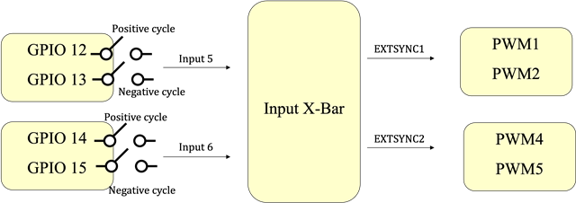
  • Just a clarification. This is what I am doing: Using Input 5 and Input 6 of Input Xbar to select one of GPIO 12-15,and that selected GPIO actually goes to EXTSYNC1/EXTSYNC2. The GPIO pins will be configured for input qualification (TZ1-TZ4).

  • Hello,

    To clarify, are you trying to synchronize the EPWMs based off of an ORed combination of the GPIO12-15 sources? Here is a high level diagram just so I can understand what it is you are trying to do:

    If this is incorrect, could you please provide a diagram of your desired system?

    Best,

    Allison 

  • Hi, this is the architecture. For one Input to Xbar, only one GPIO gets connected, based on position of switch (decided by me).

    Thanks!

  • Hi,

    Thank you for providing the diagram. If you are trying to generate synchronization using the Input X-BAR submodule INPUT5 and INPUT6, you would be limited to two GPIO inputs. If I understand correctly, you are trying to use 2 pairs of GPIO inputs (4 GPIOs total) to generate synchronization- i.e. you want to use GPIO12 and GPIO13 to synchronize PWM1 and PWM2 and also GPIO14 and PGIO15 to synchronize PWM4 and PWM5. If this is the case, you cannot use only INPUT5 and INPUT6 --> EXTSYNC1 and EXTSYNC2, as that only allows for the 2 GPIOs. 

    Instead, you can use the Digital Compare submodule with Input X-Bar for each of the 4 EPWMs to generate synchronization events. This is why, perhaps, you might have been trying to utilize TZ.

    For the Digital Compare submodule, what you could do for EPWM1 and EPWM2 is route GPIO12 and GPIO13 to TRIPIN1 and TRIPIN2 and use these to generate a Digital Compare sync event. For EPWM4 and EPWM5, you can similarly route GPIO14 and GPIO15 to TRIPIN3 and TRIPIN6 to generate another Digital Compare sync event. Note that you have to set this up for all of the 4 EPWMs individually (with EPWM 1 and 2 having the same settings, and EPWM4 and 5 having the same settings). I have highlighted the paths in the diagram below:

    In this way, your EPWM1 and 2 would both sync to the same DCAEVT1.sync event based on GPIO12 and 13, and EPWM4 and 5 would both sync to the same DCAEVT1.sync event but based on GPIO 14 and 15. As a further explanation, note that the DCAEVT1.sync events are ORed with the EPWMxSYNCI input signal (which is where the EXTSYNC1 and 2 are routed in to produce synchronization), so the sync path aligns with what you were trying to accomplish using EXTSYNC. The main difference is that the sync is no longer daisy chained, which is why you have to set up the Digital Compare path for all 4 EPWMs rather than just EPWM1 and EPWM4. 

    Let me know if you have further questions!

    Regards,

    Allison 

  • Thanks for the detailed explanation Allison. Actually, I am just going to use GPIO 12 to trigger EXTSYNC1 and GPIO 15 to trigger EXTSYNC2. GPIO 13 and GPIO 14 are there just to have provision in case I need to use them for triggering. My main question is that can TZ4 be used to connect to Input 6 and EXTSYNC2 like TZ1-3, as the technical reference manual only shows the connection of TZ1-TZ3 to  the Trip Zone as well as Digital Compare Registers? 

    Currently, I am just using GPIO 12 which is configured for input qualification to connect to INPUT 5 and EXTSYNC1.

    Thanks A LOT. Let me know if the above question makes sense.

  • Okay yes I think I understand your question now. I also think you might have some confusion on how these are all connected when you ask:

    can TZ4 be used to connect to Input 6 and EXTSYNC2 like TZ1-3

    First, to answer your most direct question, unfortunately you cannot use TZ4 as an input to any EXTSYNC like you describe. This is because TZ4 is directly sourced from the EQEP error signal and cannot be mapped to INPUT6 for EXTSYNC2 (or INPUT5 for EXTSYNC1). The module is limited in that respect.

    I also wanted to make sure your understanding is clear in regards to the rest of your statement. Yes, you are correct in saying that INPUT6 is what drives EXTSYNC2. However, TZ1-3 do not play any part in this. The signals from your 3 GPIOs go to INPUT1-3 in Input X-BAR and are then mapped to TZ1-3 respectively (and TZ1-3 are then sent to the Trip Zone module). TZ1-3 (INPUT1-3) are thus completely separate from the EXTSYNC1 and 2 (which are sourced from INPUT5 and INPUT6 respectively). Hope this helps clarify things!

    Regards,

    Allison

  • Thanks Allison. Just to understand, in order to generate a sync signal for the PWMS through EXTSYNC, it is not necessary to configure the GPIOs which are carrying the external sync signal to be configured as TZ1-TZ3? In that case, if I  directly configure Input 5/6 to take the sync signal at the GPIO 12/13 without configuring GPIO 12/13 for input qualification, would that be sufficient? (assuming that GPIO 12/13 are configured as input pins)

  • No problem! And yes, that is correct. To use EXTSYNC1 and 2, the GPIOs do not need to go to INPUT1-3 (which would wire to TZ1-3 as you said). Instead, directly configure GPIO12 to INPUT5 for EXTSYNC1 and GPIO13 to INPUT6 for EXTSYNC2. 

    To your second point, input qualification is actually a part of the GPIO module, not the EPWM module. Hence, you can still have input qualification configured for each GPIO before they enter Input X-BAR. You can refer to the Input Qualification section of the GPIO module in the TRM (page 955) for more details on this. 

    Regards,

    Allison

  • Thanks Allison. That make sense!