This thread has been locked.

If you have a related question, please click the "Ask a related question" button in the top right corner. The newly created question will be automatically linked to this question.

TMDSCNCD28388D: Converting example enet_lwip_udp to use RMII with same PHY but on custom board

Part Number: TMDSCNCD28388D
Other Parts Discussed in Thread: TMDSHSECDOCK, , C2000WARE, TMS320F28386S-Q1

TI Development Kit used:
TMDSCNCD28388D with TMDSHSECDOCK

C2000Ware used:
C2000Ware_4_03_00_00

TI example projects used:
driverlib\f2838x\examples\cm\ethernet\CCS\ethernet_c28x_config.projectspec
libraries\communications\Ethernet\third_party\lwip\examples\enet_lwip_udp

Our custom board microcontroller:
TMS320F28386S-Q1 (F28386S)

Our custom board PHY:
DP83826ERHB


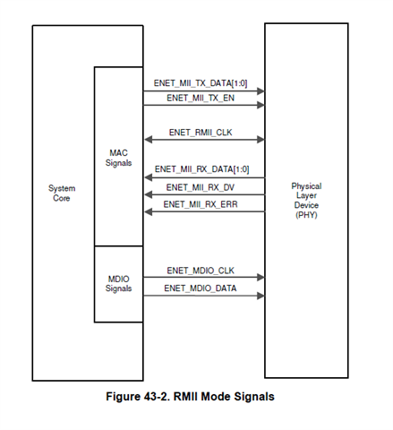
Our board uses a F28386S MCU with a TI DP83826ERHB PHY. It is designed to use RMII ethernet.

After first exercising a TI example successfully on a TI development board kit, I tried to modify
the same example to work on our custom board which uses a F28386S with the same (?) PHY using an RMII ethernet
configuration. The modified example does not work. I am including a zip file of my CCS workspace.

On our board, the CPU1 c28x program partially ran before it stopped itself due to a clock misconfiguration.
It stopped at ESTOP0 within an if-block in Device_init() of project "device.c" line 115.

A code comment there states the check to verify crystal freq is only for XTAL as the PLL source.
My board designer tells me we are using Oscillator 2 as an internal source, not XTAL, so I followed
symbol DEVICE_SETCLOCK_CONFIG to its #define in device.h line 236 using control-click in CCS.
Here I noted several things related to clocks and the clock source which had to be changed
to match our board.

I made some changes, under the assumption that I should maintain a 200Mhz sysclk freq and 125Mhz auxclk.

CHANGES MADE:

File "device.h" (project "ethernet_c28x_config):

(line 230)
I began by changing the DEVICE_OSCSRC_FREQ #define on line 230 from 25000000U to 10000000U
because my board designer told me the internal OSC2 clock runs at 10 MHz, and we use that
instead of an external oscillator.

(line 236)
#define DEVICE_SETCLOCK_CFG (SYSCTL_OSCSRC_XTAL | SYSCTL_IMULT(32) | \
SYSCTL_REFDIV(2) | SYSCTL_ODIV(2) | \
SYSCTL_SYSDIV(1) | SYSCTL_PLL_ENABLE | \
SYSCTL_DCC_BASE_1)

was changed to use OSC2, like this (note the change to IMULT value to maintain 200MHZ SYSCLK freq):

#define DEVICE_SETCLOCK_CFG (SYSCTL_OSCSRC_OSC2 | SYSCTL_IMULT(80) | \
SYSCTL_REFDIV(2) | SYSCTL_ODIV(2) | \
SYSCTL_SYSDIV(1) | SYSCTL_PLL_ENABLE | \
SYSCTL_DCC_BASE_1)

I then changed the next #define, for symbol DEVICE_SYSCLK_FREQ, to match the change to SYSCTL_IMULT
above in order to maintain 200 MHZ:

(line 245)
#define DEVICE_SYSCLK_FREQ ((DEVICE_OSCSRC_FREQ * 32) / (2 * 2 * 1))

was changed to this:

#define DEVICE_SYSCLK_FREQ ((DEVICE_OSCSRC_FREQ * 80) / (2 * 2 * 1))

(line 252)
I left alone the definition of symbol DEVICE_LSPCLK_FREQ, assuming 50 MHZ is still appropriate
(but I really don't know).

For AUXCLK, I made similar changes to adjust for our internal clock frequency and to maintain
125MHZ for AUXCLK:

(line 258)
#define DEVICE_AUXSETCLOCK_CFG (SYSCTL_AUXPLL_OSCSRC_XTAL | SYSCTL_AUXPLL_IMULT(40) | \
SYSCTL_REFDIV(2U) | SYSCTL_ODIV(4U) | \
SYSCTL_AUXPLL_DIV_1 | SYSCTL_AUXPLL_ENABLE | \
SYSCTL_DCC_BASE_0)

was changed to use OSC2, like this (note the change to IMULT to maintain 125MHZ AUXCLK freq)

#define DEVICE_AUXSETCLOCK_CFG (SYSCTL_AUXPLL_OSCSRC_OSC2 | SYSCTL_AUXPLL_IMULT(100) | \
SYSCTL_REFDIV(2U) | SYSCTL_ODIV(4U) | \
SYSCTL_AUXPLL_DIV_1 | SYSCTL_AUXPLL_ENABLE | \
SYSCTL_DCC_BASE_0)

I then changed the next #define, for symbol DEVICE_AUXCLK_FREQ, to match the change to SYSCTL_AUXPLL_IMULT
above in order to maintain 125MHZ:

(line 267)
#define DEVICE_AUXCLK_FREQ ((DEVICE_OSCSRC_FREQ * 40) / (2 * 4 * 1))

was changed to this:

#define DEVICE_AUXCLK_FREQ ((DEVICE_OSCSRC_FREQ * 100) / (2 * 4 * 1))

After making these clock related changes, I rebuilt the example and loaded both programs again and ran them.

I ran the CPU1 program, then the ARM program. This time, the CPU1 software ran to completion (as it had on
the TI board), but pings from Windows failed every time (Request timed out).

When I paused the C28x program, I saw it is in abort() at exit.c:95, called by exit() at exit.c:80.
This is expected, because the program reached its exit brace in main() as it should have done.

When I paused the CM program, I saw it is in Ethernet_resetModule() at ethernet.c:3113
(called by Ethernet_initInterface at ethernet.c:733, called by Ethernet_init at enet_lwip_udp.c:595,
called by main().

After some investigation, I found the example is using an "MII" approach to ethernet on the TI board, but
that our board uses an RMII architecture. I did some reading about the differences between the two. I saw
that I would need to change additional code in the example. So next, I attempted to make those needed changes...


Attempt to reconfigure the code for RMII (instead of default MII) ethernet:

1. Project "enet_lwip_udp", Source file "enet_lwip_udp.c"

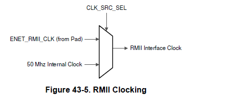
Here I changed Ethernet_init():566 to use
ETHERNET_SS_PHY_INTF_SEL_RMII instead of ETHERNET_SS_PHY_INTF_SEL_MII when assigning phyMode, like this:

initInterfaceConfig.phyMode = ETHERNET_SS_PHY_INTF_SEL_RMII; // jct rmii

I also added this line immediately after it:

initInterfaceConfig.clockSel = ETHERNET_SS_CLK_SRC_EXTERNAL; //jct rmii

2. Project "ethernet_c28x_config", Source file "cm_common_config_c28x.c":

My board designer provided me the pins our board uses for ethernet with RMII:

ETHERNET
MDC  GPIO42
MDIO GPIO43
RX_ER GPIO76
TX0 GPIO75
TX1 GPIO74
REF_CLK GPIO73
RX1 GPIO72
RX0 GPIO71
CRS_DV GPIO70
TX_EN GPIO69

RMII_INRPT GPIO68
PHY_RESET GPIO67

The main() function uses GPIO_setPinConfig() to assign specific pins for MII
ethernet and those pins are different from what my board designer provided (for RMII) on our board).

So between source lines 95 and 129 (in main()), I changed the GPIO_setPinConfig() calls to use the
pin numbers provided by my board design engineer for our board's RMII ethernet.

On lines 131-136 is a series of statements to "bring the external PHY out of Power down" and
on lines 138-144 is a series of statements to "bring the external PHY out of Reset".

My board designer has a line from GPIO 68 connecting to the PHY's PWRDN/INT pin, so I changed the pin
number from GPIO 108 to GPIO 68 in lines 131-136. The comment here in the example states this is to
drive this pin high to bring the external PHY out of Power down.

My board designer shows a PHY_RESET for Ethernet as GPIO67 (not GPIO 119 as used in the example) so
I changed the pin from GPIO 119 to 67 in lines 138-144. The comment here in the example states this is to
drive this pin high to bring the external PHY out of Reset

After making the above changes, I still cannot ping our board when the software is running. The main
loop of the example executes, but never enters its if-block because the board is not reachable via ethernet
(a client cannot connect to it over UDP). Are additional (or different) changes required to the example?
If not, then perhaps our board has a design flaw, or the PHY is not sending us a clock. I believe the PHY
is the same part number used on the TI development board we are using (the unmodified/MII example works on
that board). If this code looks correct, what avenues should I explore next?


TiSupport.zip

  • Hi, 

    Are you able to read and write to the PHY registers ?  PHY also has to be configured in RMII mode.  

    Pls refer the example ethernet_ex2_phy_loopback provided within C2000Ware located at <C200Ware>driverlib\f2838x\examples\cm\ethernet\CCS.  This reads the PHY registers and configures it in MII mode.   Similarly , you will have to configure the PHY to be in RMII mode. 

    Also make sure that RMII interface signals are correctly configured

    If you are configuring the ENET_RMII_CLK as External Clock, then the PHY/external device should provide the clock.

    Best Regards

    Siddharth

  • Siddharth,  as you point out, "ethernet_ex2_phy_loopback" example reads and writes to a PHY register. However, that is merely for setting loopback mode for that test, and seems to have nothing to do with configuring that PHY for RMII mode.  In my application, I don't want packets to loop back.  I want the PHY to transmit outgoing packets. Is there something about the PHY registers that must be prepared specifically for RMII?  From the example you are pointing too, very little seems to concern RMII (vs. MII) configuration: one line in main() which sets initInterfaceConfig.phyMode.  I had already changed such a line in my own code to assign the RMII value to that field: 

    initInterfaceConfig.phyMode = ETHERNET_SS_PHY_INTF_SEL_RMII;

    as detailed above in my original post under number 1.  I also did this:

    initInterfaceConfig.clockSel = ETHERNET_SS_CLK_SRC_EXTERNAL; 

    Yes, we plan on using the clock from the DP83826ERHB PHY. 

    In my c28x code, as detailed above, I configured the pins according to our board schematics, for RMII (or so I intended).  Please review what I changed on the lines of code as described above under number 2. 

    I understand your point that any PHY connected to the microcontroller will need registers setup for any non-default configuration required.

    I have this document from the TI site for TI PHY  DP83826ERHB: "https://www.ti.com/lit/ds/symlink/dp83826e.pdf?ts=1692824765093&ref_url=https%253A%252F%252Fwww.ti.com%252Fproduct%252FDP83826".

    I will study it carefully for anything related to register setup for RMII mode.  It is a close part number to the PHY referenced in the example you cited, but I note that it is not identical. Again, I saw nothing in the example you cited related to REGISTER writes to a PHY for RMII configuration, so I was confused by your reply in that respect.

    [EDIT 8/24 p.m.] - 

    Later today 8/24 after reviewing the PHY documentation linked above, I see that our board is using "pin boostraps" to configure some PHY features without the need for writing to PHY registers. For example, PHY pin 1 is shorted to GND, which means our PHY is in "BASIC mode". In BASIC mode, Pin 21 is for issuing an interrupt only, and does not function as a PWRDN pin at all. So I commented-out code from the examples which tries to bring the PHY out of "power-down" by asserting that pin.  Also, our board uses STRAP4 on pin 18 to bring up the PHY for RMII mode. So YES, the PHY is already configured for RMII mode.  I have set the pin mux (as seen in my notes above) for the RMII signals.  Still, I have no ping after the code runs.  

    After reviewing what I have done and described, what am I missing (if anything) in the software configuration for using RMII mode instead of MII?  Is there anything lacking or incorrect in what I've done in software that would prevent pings from working or my callback from being invoked?

  • As detailed in my Aug 24 post, the board uses "pin bootstraps" to configure the DP83826ERHB PHY in hardware in its BASIC mode and for RMII ethernet. 

    As mentioned earlier, my code sets phMode for RMII and for the external PHY clock:

    initInterfaceConfig.phyMode = ETHERNET_SS_PHY_INTF_SEL_RMII;

    initInterfaceConfig.clockSel = ETHERNET_SS_CLK_SRC_EXTERNAL;

    I exercised the example you cited (ethernet_ex2_phy_loopback) with the C28x project setup for the correct RMII pin assignments, etc, and the CM project assigning the phyMode and clockSel.  The statement which reads the PHY register in the example returns 0xFFFF, which does not seem right.

    I can't see what's missing (if anything). Do you have any ideas about what else I can do in software that I should be doing?  Or do you have any ideas on further troubleshooting this?  

  • Hi, 

    Is there a way to confirm that the PHY is configured correctly ?   which PHY register are you trying to read? .

    Pls read the RCSR register to determine the PHY RMII configuration.  

    Following is the code snippet for reference.

    phyRegContent = Ethernet_readPHYRegister(EMAC_BASE,0x1); //Base,Address

    //
    //Address 0 of PHY corresponds to Basic Mode Control Register(BMCR)
    //Read the register to know the state
    //
    phyRegContent= Ethernet_readPHYRegister(EMAC_BASE,0);

    //
    //Bit 12 of BMCR configures the Auto-Negotiation - turn it off
    //
    phyRegContent &= 0xEFFF;
    //Ethernet_writePHYRegister(EMAC_BASE,0,phyRegContent);

    //
    //Bit 8 of BMCR configures the duplex capability - set to full duplex
    //
    phyRegContent |= 0x100;
    Ethernet_writePHYRegister(EMAC_BASE,0,phyRegContent);

    //
    //Read back the BMCR register to confirm that it is configured properly
    //
    phyRegContent= Ethernet_readPHYRegister(EMAC_BASE,0);

    // configure PHY in RMII Mode in RMII and Status Register (RCSR)
    phyRegContent= Ethernet_readPHYRegister(EMAC_BASE,0x17);

    phyRegContent |= 0x20;
    Ethernet_writePHYRegister(EMAC_BASE,0x17,phyRegContent);

    //
    //Read back the RCSR register to confirm that it is configured properly
    //
    phyRegContent= Ethernet_readPHYRegister(EMAC_BASE,0x17);

    Also, observed that you are selecting external clock for RMII clocking.  In this case, the ENET_RMII_CLK pin of the device should be provided with the required 50-MHz clock.

    Best Regards

    Siddharth

  • Is there a way to confirm that the PHY is configured correctly ?   which PHY register are you trying to read? .

    As mentioned in my prior post, I used the example you cited (ethernet_ex2_phy_loopback).  That example reads the BMCR register.  A read of that register returned 0xFFFF.  The portion of the example main() which does this is as follows:

        //
        //Low Frequency
        //value of 5 for selecting the slowest possible MDIO Clock
        //Clause 22 mode
        //
        Ethernet_configureMDIO(EMAC_BASE,0,5,0);
    
        //
        //The DP83822 External PHY in Control Card
        //takes a PHY address of 1 by default
        //Configure the MDIO module to use PHY address of 0x1
        //
        Ethernet_configurePHYAddress(EMAC_BASE,1);
    
        //
        //Address 0 of PHY corresponds to Basic Mode Control Register(BMCR)
        //Read the register to know the state
        //
        phyRegContent= Ethernet_readPHYRegister(EMAC_BASE,0);
    

    I see you have posted some additional instructions to use MDIO to query the PHY configuration and I will paste those statements into the example and execute it. 

    Also, I am following-up with my board design engineer to verify the clock signal is being sent by the PHY to the microcontroller.

    I will follow up immediately afterward here with the results.

    I added the statements and executed. Here are the results. The hex number in the left margin is the value of phyRegContent after each execution of each statement which might change it:

    0x0
        phyRegContent = Ethernet_readPHYRegister(EMAC_BASE,0x1); //Base,Address
    0xFFFF
    
        //
        //Address 0 of PHY corresponds to Basic Mode Control Register(BMCR)
        //Read the register to know the state
        //
        phyRegContent= Ethernet_readPHYRegister(EMAC_BASE,0);
    0xFFFF
    
        //
        //Bit 12 of BMCR configures the Auto-Negotiation - turn it off
        //
        phyRegContent &= 0xEFFF;
    0xEFFF
        //Ethernet_writePHYRegister(EMAC_BASE,0,phyRegContent);
        //
        //Bit 8 of BMCR configures the duplex capability - set to full duplex
        //
        phyRegContent |= 0x100;
    0xEFFF
        Ethernet_writePHYRegister(EMAC_BASE,0,phyRegContent);
        //
        //Read back the BMCR register to confirm that it is configured properly
        //
        phyRegContent= Ethernet_readPHYRegister(EMAC_BASE,0);
    0xFFFF
        // configure PHY in RMII Mode in RMII and Status Register (RCSR)
        phyRegContent= Ethernet_readPHYRegister(EMAC_BASE,0x17);
    0xFFFF
        phyRegContent |= 0x20;
    0xFFFF
        Ethernet_writePHYRegister(EMAC_BASE,0x17,phyRegContent);
        //
        //Read back the RCSR register to confirm that it is configured properly
        //
        phyRegContent= Ethernet_readPHYRegister(EMAC_BASE,0x17);
    0xFFFF
    

  • James, 

    The EMAC configuration looks correct to me.  If the PHY and the RMII clock is configured correctly , then it should work fine. 

    Let us know your observations regarding the Clock.

    Best Regards

    Siddharth

  • Thank you for evaluating the EMAC configuration. I'll let you know what I find about the PHY clock output to the microcontroller. I'm asking my colleague if we can probe the signal.  But you were guiding me to use MDIO to check the PHY configuration. Does it seem wrong to you that my PHY register read operations are always returning 0xFFFF?  What can cause that?  That doesn't seem right to me.

  • James, 

    The register always returning 0xFFFF doesn;t seem right.   Will request the PHY team to look in to it and see if something is missing.

    Best Regards

    Siddharth

  • I look forward to hearing from you or the PHY team about the MDIO so we can look at PHY registers.  In answer to  your question about the PHY clock output, we did verify the 50 MHz clock is being output from the PHY. So far, you've reviewed my EMAC configuration (looks good), and we have verified the PHY is putting out the 50 MHz clock.  Reads over the MDIO serial interface are returning 0xFF for the BMCR and RCSR registers, which we agree is probably incorrect.  That is where things stand at the moment.  Do you have any other ideas?

  • Hi James,

    Can you please let me know if the register access is not working from the start or you just lost the access recently?

    Can you also share the schematic of the design?

    --
    Regards,
    Gokul.

  • Hi Gokul.  No, I have not yet seen PHY register access work on our board (not working from the start).  We have a Proprietary Information Agreement with TI, so yes, we can share design schematics in a non-public forum.  On 9/14 I requested a meeting (for using screen share) via Brad Caldwell (TI Processor Field Applications) so we can share design details with your team.  Mr. Caldwell replied, "I just pinged our apps manager again to bring this to his attention. I asked if we can get a call setup with an expert, waiting to see what he comes up with. I'll get back to you."  I have not heard back from Brad Caldwell about setting up the call yet.  On 9/21 I emailed him, explaining we are waiting for news about setting up a call with screen-share.

  • Hi James,

    To understand why the MDIO access is not available, we need to check

    1. Circuit or schematic of the MDC, MDIO in your design
    2. Health of the PHY (whether the PHY powered-up, power-up timing etc.)

    I can share my email address over a personal message to you. You can share the schematic over email.

    On the health of the device, can you please let me know the following?

    1. Is there a link observable on the link partner when it is connected?
    2. During the hardware bring-up, are there any signs that the hardware is working fine that are observable by you or your team?

    Can you please do the following captures?

    1. Capture-1:
      Signal on MDI lines (i.e., TD_P and TD_M)
      Disconnect the link partner and terminate TD_P and TD_M with a 100 ohm differential termination.
      Probe the TD_P and TD_M differential signal using a differential probe and capture the waveform.

    2. Capture-2:
      Signal on MDC, MDIO when register access is done
      Read register 0x1 and capture the waveform of MDC and MDIO in a single snap which is zoomed in to see the edge transitions of MDC, MDIO.

    We will look into power-up timing and other captures if the above two captures yield us no results.

    --
    Regards,
    Gokul.