Hi,
In the BissC example the ePWM1 is started and Action on TZ A & B are setup.
// Set the PWMA and B high as default values of bissC clk.
SysCtl_enablePeripheral(SYSCTL_PERIPH_CLK_EPWM1);
// Action on TZ A
EPWM_setTripZoneAction(EPWM4_BASE,
EPWM_TZ_ACTION_EVENT_TZA,
EPWM_TZ_ACTION_HIGH);
// Action on TZ B
EPWM_setTripZoneAction(EPWM4_BASE,
EPWM_TZ_ACTION_EVENT_TZB,
EPWM_TZ_ACTION_HIGH);
// Forces a Trip Zone event
EPWM_forceTripZoneEvent(EPWM4_BASE, EPWM_TZ_FORCE_EVENT_OST);
}
Then it "appears" that ePWM1 is setup in the CLB global inputs to connect to Tile 4 in CLB_IN0 what is this doing in the CLB code example. Is it helping to provide the BissC and SPI clock?
CLB_configGlobalInputMux(CLB4_BASE, CLB_IN0, CLB_GLOBAL_IN_MUX_EPWM1A);
I cannot see anywhere in the example where the EPWM1 is setup for anything but the Trip Zones
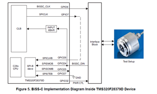
Finally in the example where are the BissC and SPI clocks generated out of the CLB? See the below diagram


