- Ask a related questionWhat is a related question?A related question is a question created from another question. When the related question is created, it will be automatically linked to the original question.

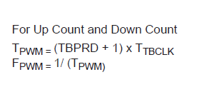
Having a severe problem in developing our pulse width modulator, I have set the TBPRD to 1200 such that the frequency is around 166kHz. However on my scope I am seeing my switching waveform at just 10kHz.
Here is the code for this part of the controller:
void initEPWM1(void) {
// Set up time-base clock.
EPWM_setTimeBasePeriod(EPWM1_BASE, EPWM_TIMER_TBPRD);
EPWM_setPhaseShift(EPWM1_BASE, 0);
EPWM_setTimeBaseCounter(EPWM1_BASE, 0);
// Counter compare config for EPWM1. May just need CMPA if use FED/RED.
EPWM_setCounterCompareValue(EPWM1_BASE,
EPWM_COUNTER_COMPARE_A,
EPWM_TIMER_TBPRD/2);
EPWM_setCounterCompareValue(EPWM1_BASE,
EPWM_COUNTER_COMPARE_B,
EPWM_TIMER_TBPRD/2);
// Set up counter mode.
EPWM_setTimeBaseCounterMode(EPWM1_BASE, EPWM_COUNTER_MODE_UP);
EPWM_disablePhaseShiftLoad(EPWM1_BASE);
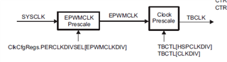
EPWM_setClockPrescaler(EPWM1_BASE,
EPWM_CLOCK_DIVIDER_2,
EPWM_HSCLOCK_DIVIDER_2);
// Set up PWM Shadowing. Load on CTR ZRO.
EPWM_setCounterCompareShadowLoadMode(EPWM1_BASE,
EPWM_COUNTER_COMPARE_A,
EPWM_COMP_LOAD_ON_CNTR_ZERO);
EPWM_setCounterCompareShadowLoadMode(EPWM1_BASE,
EPWM_COUNTER_COMPARE_B,
EPWM_COMP_LOAD_ON_CNTR_ZERO);
// Set up the action qualifier.
EPWM_setActionQualifierAction(EPWM1_BASE,
EPWM_AQ_OUTPUT_A,
EPWM_AQ_OUTPUT_HIGH,
EPWM_AQ_OUTPUT_ON_TIMEBASE_ZERO);
EPWM_setActionQualifierAction(EPWM1_BASE,
EPWM_AQ_OUTPUT_B,
EPWM_AQ_OUTPUT_LOW,
EPWM_AQ_OUTPUT_ON_TIMEBASE_ZERO);
EPWM_setActionQualifierAction(EPWM1_BASE,
EPWM_AQ_OUTPUT_A,
EPWM_AQ_OUTPUT_LOW,
EPWM_AQ_OUTPUT_ON_TIMEBASE_UP_CMPA);
EPWM_setActionQualifierAction(EPWM1_BASE,
EPWM_AQ_OUTPUT_B,
EPWM_AQ_OUTPUT_HIGH,
EPWM_AQ_OUTPUT_ON_TIMEBASE_UP_CMPA);
// Interrupt where we will change execute control code.
// Select INT on time base counter zero event
// Enable INT, but generate on the 15th event
// Bandwidth is then FSW/15.
EPWM_setInterruptSource(EPWM1_BASE, EPWM_INT_TBCTR_ZERO);
EPWM_enableInterrupt(EPWM1_BASE);
EPWM_setInterruptEventCount(EPWM1_BASE, 15);
}
void initEPWM2(void) {
// Set up time-base clock.
EPWM_setTimeBasePeriod(EPWM2_BASE, EPWM_TIMER_TBPRD);
// Initially zero, but test with different TBPHS.
// Ensure Time base is set to same value as phase shift.
EPWM_setPhaseShift(EPWM2_BASE, 300);
EPWM_setTimeBaseCounter(EPWM2_BASE, 300);
// Counter compare config for EPWM2. May just need CMPA if use FED/RED.
EPWM_setCounterCompareValue(EPWM2_BASE,
EPWM_COUNTER_COMPARE_A,
EPWM_TIMER_TBPRD/2);
EPWM_setCounterCompareValue(EPWM2_BASE,
EPWM_COUNTER_COMPARE_B,
EPWM_TIMER_TBPRD/2);
// Set up counter mode.
EPWM_setTimeBaseCounterMode(EPWM2_BASE, EPWM_COUNTER_MODE_UP);
EPWM_disablePhaseShiftLoad(EPWM2_BASE);
EPWM_setClockPrescaler(EPWM2_BASE,
EPWM_CLOCK_DIVIDER_2,
EPWM_HSCLOCK_DIVIDER_2);
// Set up PWM Shadowing. Load on CTR ZRO.
EPWM_setCounterCompareShadowLoadMode(EPWM2_BASE,
EPWM_COUNTER_COMPARE_A,
EPWM_COMP_LOAD_ON_CNTR_ZERO);
EPWM_setCounterCompareShadowLoadMode(EPWM2_BASE,
EPWM_COUNTER_COMPARE_B,
EPWM_COMP_LOAD_ON_CNTR_ZERO);
// Set up the action qualifier.
// Scope these and check if right, most likely need to be different to EPWM1.
EPWM_setActionQualifierAction(EPWM2_BASE,
EPWM_AQ_OUTPUT_A,
EPWM_AQ_OUTPUT_HIGH,
EPWM_AQ_OUTPUT_ON_TIMEBASE_ZERO);
EPWM_setActionQualifierAction(EPWM2_BASE,
EPWM_AQ_OUTPUT_B,
EPWM_AQ_OUTPUT_LOW,
EPWM_AQ_OUTPUT_ON_TIMEBASE_ZERO);
EPWM_setActionQualifierAction(EPWM2_BASE,
EPWM_AQ_OUTPUT_A,
EPWM_AQ_OUTPUT_LOW,
EPWM_AQ_OUTPUT_ON_TIMEBASE_UP_CMPA);
EPWM_setActionQualifierAction(EPWM2_BASE,
EPWM_AQ_OUTPUT_B,
EPWM_AQ_OUTPUT_HIGH,
EPWM_AQ_OUTPUT_ON_TIMEBASE_UP_CMPA);
// Interrupt where we will change execute control code.
// Select INT on time base counter zero event
// Enable INT, but generate on the 15th event
// Bandwidth is then FSW/15.
EPWM_setInterruptSource(EPWM2_BASE, EPWM_INT_TBCTR_ZERO);
EPWM_enableInterrupt(EPWM2_BASE);
EPWM_setInterruptEventCount(EPWM2_BASE, 15);
}
void setupEPWMActiveHighComplementary() {
// As always, use EPWMA as the input for both RED and FED.
EPWM_setRisingEdgeDeadBandDelayInput(EPWM1_BASE, EPWM_DB_INPUT_EPWMA);
EPWM_setRisingEdgeDeadBandDelayInput(EPWM2_BASE, EPWM_DB_INPUT_EPWMA);
EPWM_setFallingEdgeDeadBandDelayInput(EPWM1_BASE, EPWM_DB_INPUT_EPWMA);
EPWM_setFallingEdgeDeadBandDelayInput(EPWM2_BASE, EPWM_DB_INPUT_EPWMA);
// Set the rising and falling edge delay values. One percent of switching period, for now.
EPWM_setFallingEdgeDelayCount(EPWM1_BASE, EPWM_TIMER_TBPRD/100);
EPWM_setFallingEdgeDelayCount(EPWM2_BASE, EPWM_TIMER_TBPRD/100);
EPWM_setRisingEdgeDelayCount(EPWM1_BASE, EPWM_TIMER_TBPRD/100);
EPWM_setRisingEdgeDelayCount(EPWM2_BASE, EPWM_TIMER_TBPRD/100);
// Invert only the falling edge delayed output for active-high complementary mode.
EPWM_setDeadBandDelayPolarity(EPWM1_BASE, EPWM_DB_RED, EPWM_DB_POLARITY_ACTIVE_HIGH);
EPWM_setDeadBandDelayPolarity(EPWM1_BASE, EPWM_DB_FED, EPWM_DB_POLARITY_ACTIVE_LOW);
EPWM_setDeadBandDelayPolarity(EPWM2_BASE, EPWM_DB_RED, EPWM_DB_POLARITY_ACTIVE_HIGH);
EPWM_setDeadBandDelayPolarity(EPWM2_BASE, EPWM_DB_FED, EPWM_DB_POLARITY_ACTIVE_LOW);
// Use the delayed signals instead of the original signals.
EPWM_setDeadBandDelayMode(EPWM1_BASE, EPWM_DB_RED, true);
EPWM_setDeadBandDelayMode(EPWM1_BASE, EPWM_DB_FED, true);
EPWM_setDeadBandDelayMode(EPWM2_BASE, EPWM_DB_RED, true);
EPWM_setDeadBandDelayMode(EPWM2_BASE, EPWM_DB_FED, true);
// Importantly, do not switch output A with output B.
EPWM_setDeadBandOutputSwapMode(EPWM1_BASE, EPWM_DB_OUTPUT_A, false);
EPWM_setDeadBandOutputSwapMode(EPWM1_BASE, EPWM_DB_OUTPUT_B, false);
EPWM_setDeadBandOutputSwapMode(EPWM2_BASE, EPWM_DB_OUTPUT_A, false);
EPWM_setDeadBandOutputSwapMode(EPWM2_BASE, EPWM_DB_OUTPUT_B, false);
}
EPWM2 is set up the exact same way as EPWM with just a variable phase shift, but also switches at just 10kHz.
Could anyone point me in the direction for what may be happening here?
Best regards,
JMH