This thread has been locked.

If you have a related question, please click the "Ask a related question" button in the top right corner. The newly created question will be automatically linked to this question.

TIDM-HV-1PH-DCAC: Transistors break on start-up, closed loop

Part Number: TIDM-HV-1PH-DCAC

Hi, 

I'm working on a single-phase inverter based on the TIDM-HV-1PH-DCAC demo board. The system seems to work, but randomly, my transistors break on start-up. I'm in a closed voltage/current loop. The system works on resistive loads at maximum power and the breakage does not depend on the load.
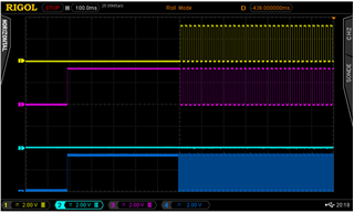
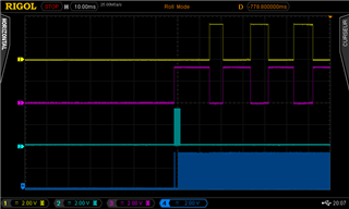
After searching for the cause of the problem, it turns out that the transistors, which switch at 50Hz, are erratically controlled at start-up. I've attached screenshots of the phenomenon: 

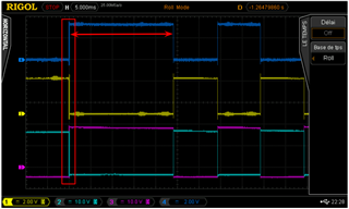
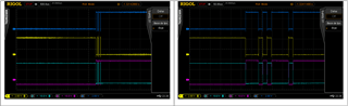
Zoom in on the framed area: 

The arrangement of the probes is as follows:

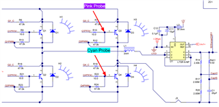
The blue probe corresponds to the control of transistor Q1 on the microcontroller.
The yellow probe corresponds to the control of transistor Q2 on the microcontroller.
The pink probe corresponds to the command taken on the gate of Q1.
The yellow probe corresponds to the command taken from the gate of Q2.

My hypothesis is that the problem could come from PWM initialization, maybe they're started before initialization?

Do you have any idea how to solve this problem?

Thank you very much!

  • Hello Alex 

    What do you mean by Transistor break? Did it get damaged or just some sound due to rapid turn on and off?
    I saw the waveform. Seems weird. I am guessing you are following the userguide and running the Demo mode. When exactly this occurs?  Does it occur as soon as you raise the DC bus to be greater than the maximum voltage of the AC nominal?

    Thanks

    Amir

  • Hi,
    thanks for your answer
    The transistors of a bridge are short-circuited. This doesn't happen often, but it can happen to 1 in 20 start-ups.

    Yes, there's something odd about it, especially as the frequency of this "disturbance" is at the switching frequency of the high-frequency bridge (20kHz in the demo).
    As far as our setup is concerned, we started from the demo board to use the setup on our system. The problem occurs at start-up, when the DC bus is already present and the inverter is controlled with the start command. The first commands are erratic, then stabilize and return to normal.

    To simulate the problem and analyze it more simply, I then used this circuit without the transistors (and power) to analyze the microcontroller commands at start-up, and obtained the same signals.

    Thanks

  • Hello Alex

    The transistors of a bridge are short-circuited. This doesn't happen often, but it can happen to 1 in 20 start-ups

    From your answer, I am guessing the transistors are not permanently short circuited (not permanently damaged). Also, it gets short circuited only for the duration it gets the pulse from microcontroller. I see from the waveform, the pulses are complementary so it does not short circuit the full leg. So you should not be getting over current trip. 

    To answer your question, the low frequency transistor is controlled based on the sign of duty ratio which compute in 20kHz ISR. It is possible that duty may be changing its sign from positive to negative at the startup which makes the low frequency transistor to change its state at the rate of 20kHz. This can be avoided using a soft start in the software which is not included in the existing software. Pls have look on this function for detail

    static inline void updateInverterPWM(uint32_t base1, uint32_t base2,float32_t duty)

    Thanks

    Amir

  • When transistors are short-circuited (about 1 out of 20 times), they're out of order and need to be replaced by new ones. Damaged transistors are cut in two by the shock (hence my hypothesis of a break due to too high a current).
    The complementary nature of the controls is good, as the transitors never drive at the same time.

    As for the soft start, my hypothesis is the same as yours: the low-frequency bridge switches more often than expected (due to changes in the sign of the duty), and as there's no smoothing choke self there, the current draw from the capacitor must be damaging the component (perhaps heating it up more than normal as a result). To test this, I first added a time delay that blocked the commands in the updateInverterPWM function (yellow and pink are low frequency commands) :

    Then a soft start that blocks the low frequency command for part of the period. This fixes the control signals by avoiding erratic switching yellow and pink are low frequency commands and cyan is the soft start duration)

    I'm going to test this hypothesis to see if it's correct. 

    Thank you.

  • ok Alex.

    Good luck

    Amir Hussain