This thread has been locked.

If you have a related question, please click the "Ask a related question" button in the top right corner. The newly created question will be automatically linked to this question.

LAUNCHXL-F28379D: Using fcl_f2837x_tmdxiddk FOC project on Launchxl-F28379D with BoostXL-3phganinv

Part Number: LAUNCHXL-F28379D
Other Parts Discussed in Thread: BOOSTXL-3PHGANINV, TMDXIDDK379D, TMDSCNCD28379D, , BOOSTXL-POSMGR

Hi Texas Instruments,

I hope you can help with this, I will outline this to convey the message a bit better

What we want to do

I am currently trying to drive a PMSM with an SPI Absolute Encoder using boostXL-3phganinv

I know TMDXIDDK379D is probably a better board, but we really want to test this using GaN inverter instead of regular MOSFETs

Also, we have HSEC 180 Pin Docking Card and TMDSCNCD28379D Control Card, but decided not to use it as we do not have a proper PCB to interface the BoostXl-3phganinv other than some jumper cables.

What we evaluated

  • Initially tried to use the dual-axis servo drive project
    • However, I'm not very familiar with CLA's and it was difficult to figure out how we can disable the eQEP saving to pangle from CLA
    • Any suggestion on where to put disable macro for eQEP would be appreciated if possible

What we tried

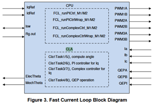
  • So i decided to use the TMDXIDDK FCL project on LaunchXL-F28379D
  • I copied over all of the PWM and ADC masks as seen below
    //
    // ADC and PWM Related defines for M1
    //
    #define M1_IU_ADC_BASE         ADCC_BASE           //C2, NC: Set up based board
    #define M1_IV_ADC_BASE         ADCB_BASE           //B2, NC: Set up based board
    #define M1_IW_ADC_BASE         ADCA_BASE           //A2, NC: Set up based board
    #define M1_VDC_ADC_BASE        ADCD_BASE           //D14, NC: Set up based board
    
    #define M1_IU_ADCRESULT_BASE   ADCCRESULT_BASE     //C2, NC: Set up based board
    #define M1_IV_ADCRESULT_BASE   ADCBRESULT_BASE     //B2, NC: Set up based board
    #define M1_IW_ADCRESULT_BASE   ADCARESULT_BASE     //A2, NC: Set up based board
    #define M1_VDC_ADCRESULT_BASE  ADCDRESULT_BASE     //D14, NC: Set up based board
    
    #define M1_IU_ADC_CH_NUM       ADC_CH_ADCIN2       //C2, NC: Set up based board
    #define M1_IV_ADC_CH_NUM       ADC_CH_ADCIN2       //B2, NC: Set up based board
    #define M1_IW_ADC_CH_NUM       ADC_CH_ADCIN2       //A2, NC: Set up based board
    #define M1_VDC_ADC_CH_NUM      ADC_CH_ADCIN14      //D14, NC: Set up based board
    
    #define M1_IU_ADC_SOC_NUM      ADC_SOC_NUMBER0     //C2, NC: Set up based board
    #define M1_IV_ADC_SOC_NUM      ADC_SOC_NUMBER0     //B2, NC: Set up based board
    #define M1_IW_ADC_SOC_NUM      ADC_SOC_NUMBER0     //A2, NC: Set up based board
    #define M1_VDC_ADC_SOC_NUM     ADC_SOC_NUMBER0     //D14, NC: Set up based board
    
    #define M1_IU_ADC_PPB_NUM      ADC_PPB_NUMBER1     //C2, NC: Set up based board
    #define M1_IV_ADC_PPB_NUM      ADC_PPB_NUMBER1     //B2, NC: Set up based board
    #define M1_IW_ADC_PPB_NUM      ADC_PPB_NUMBER1     //A2, NC: Set up based board
    #define M1_VDC_ADC_PPB_NUM     ADC_PPB_NUMBER1     //D14, NC: Set up based board
    
    #define M1_U_CMPSS_BASE        CMPSS6_BASE         // NC: Set up based board
    #define M1_V_CMPSS_BASE        CMPSS3_BASE         // NC: Set up based board
    #define M1_W_CMPSS_BASE        CMPSS1_BASE         // NC: Set up based board
    
    #define M1_ADC_TRIGGER_SOC     ADC_TRIGGER_EPWM1_SOCA  // NC: Set up based board
    
    #define M1_U_PWM_BASE          EPWM1_BASE          // NC: Set up based board
    #define M1_V_PWM_BASE          EPWM2_BASE          // NC: Set up based board
    #define M1_W_PWM_BASE          EPWM3_BASE          // NC: Set up based board
    
    //
    // Analog scaling with ADC
    //
    #define M1_ADC_PU_SCALE_FACTOR          0.000244140625     // 1/2^12
    #define M1_ADC_PU_PPB_SCALE_FACTOR      0.000488281250     // 1/2^11
    
    // Current Scale
    //
    #define M1_MAXIMUM_SCALE_CURRENT        27.0
    #define M1_CURRENT_SF                   (M1_MAXIMUM_SCALE_CURRENT / 4096.0)
    #define M1_CURRENT_INV_SF               (4096.0 / M1_MAXIMUM_SCALE_CURRENT)
    
    //
    // Voltage Scale
    //
    #define M1_MAXIMUM_SCALE_VOLATGE        74.1
    #define M1_VOLTAGE_SF                   (M1_MAXIMUM_SCALE_VOLATGE / 4096.0)
    #define M1_VOLTAGE_INV_SF               (4096.0 / M1_MAXIMUM_SCALE_VOLATGE)
  • Configured all of the GPIO for my needs
    void configureGPIO(void)
    {
        uint16_t pin;
    
        //
        // main inverter PWM GPIO init
        // PWM1 - U
        // PWM2 - V
        // PWM3 - W
        //
        // GPIO0->EPWM1A->UH_M1
        GPIO_setMasterCore(0, GPIO_CORE_CPU1);
        GPIO_setPinConfig(GPIO_0_EPWM1A);
        GPIO_setPadConfig(0, GPIO_PIN_TYPE_STD);
    
        // GPIO1->EPWM1B->UL_M1
        GPIO_setMasterCore(1, GPIO_CORE_CPU1);
        GPIO_setPinConfig(GPIO_1_EPWM1B);
        GPIO_setPadConfig(1, GPIO_PIN_TYPE_STD);
    
        // GPIO2->EPWM2A->VH_M1
        GPIO_setMasterCore(2, GPIO_CORE_CPU1);
        GPIO_setPinConfig(GPIO_2_EPWM2A);
        GPIO_setPadConfig(2, GPIO_PIN_TYPE_STD);
    
        // GPIO3->EPWM2B->VL_M1
        GPIO_setMasterCore(3, GPIO_CORE_CPU1);
        GPIO_setPinConfig(GPIO_3_EPWM2B);
        GPIO_setPadConfig(3, GPIO_PIN_TYPE_STD);
    
        // GPIO4->EPWM3A->WH_M1
        GPIO_setMasterCore(4, GPIO_CORE_CPU1);
        GPIO_setPinConfig(GPIO_4_EPWM3A);
        GPIO_setPadConfig(4, GPIO_PIN_TYPE_STD);
    
        // GPIO5->EPWM3B->WL_M1
        GPIO_setMasterCore(5, GPIO_CORE_CPU1);
        GPIO_setPinConfig(GPIO_5_EPWM3B);
        GPIO_setPadConfig(5, GPIO_PIN_TYPE_STD);
    
    
        //
        // Configure GPIO8 as ePWM5A for SD1, Ch1/2 clock
        // Configure GPIO9 as ePWM5B for SD1, Ch3 clock
        //
        GPIO_setPadConfig(8, GPIO_PIN_TYPE_STD);
        GPIO_setPinConfig(GPIO_8_EPWM5A);
    
        GPIO_setPadConfig(9, GPIO_PIN_TYPE_STD);
        GPIO_setPinConfig(GPIO_9_EPWM5B);
    
        //
        // GPIO18 is used as PushPull output to indicate the end of computation when
        // compared against the SOC signal
        GPIO_setMasterCore(18, GPIO_CORE_CPU1);
        GPIO_setPinConfig(GPIO_18_GPIO18);
        GPIO_setPadConfig(18, GPIO_PIN_TYPE_STD);
        GPIO_setDirectionMode(18, GPIO_DIR_MODE_OUT);
    
        //
        // Setup GPIO for QEP operation
        //
        // QEP1A
        GPIO_setMasterCore(20, GPIO_CORE_CPU1);
        GPIO_setPadConfig(20, GPIO_PIN_TYPE_STD);
        GPIO_setDirectionMode(20, GPIO_DIR_MODE_IN);
        GPIO_setQualificationMode(20, GPIO_QUAL_3SAMPLE);
        GPIO_setPinConfig(GPIO_20_EQEP1A);
    
        // QEP1B
        GPIO_setMasterCore(21, GPIO_CORE_CPU1);
        GPIO_setPadConfig(21, GPIO_PIN_TYPE_STD);
        GPIO_setDirectionMode(21, GPIO_DIR_MODE_IN);
        GPIO_setQualificationMode(21, GPIO_QUAL_3SAMPLE);
        GPIO_setPinConfig(GPIO_21_EQEP1B);
    
        // QEP1I
        GPIO_setMasterCore(23, GPIO_CORE_CPU1);
        GPIO_setPadConfig(23, GPIO_PIN_TYPE_STD);
        GPIO_setDirectionMode(23, GPIO_DIR_MODE_IN);
        GPIO_setQualificationMode(23, GPIO_QUAL_3SAMPLE);
        GPIO_setPinConfig(GPIO_23_EQEP1I);
    
        // GPIO28->SCIRXDA
        GPIO_setMasterCore(28, GPIO_CORE_CPU1);
        GPIO_setPadConfig(28, GPIO_PIN_TYPE_STD);
        GPIO_setPinConfig(GPIO_28_SCIRXDA);
    
        // GPIO29->SCITXDA
        GPIO_setMasterCore(29, GPIO_CORE_CPU1);
        GPIO_setPadConfig(29, GPIO_PIN_TYPE_STD);
        GPIO_setPinConfig(GPIO_29_SCITXDA);
    
        // Configure GPIO used for Trip Mechanism
    
        // GPIO input for reading the status of the LEM-overcurrent macro block
        // (active low), GPIO40 could trip PWM based on this, if desired
        // Configure as Input
        GPIO_setPinConfig(GPIO_40_GPIO40);           // choose GPIO for mux option
        GPIO_setDirectionMode(40, GPIO_DIR_MODE_IN); // set as input
        GPIO_setPadConfig(40, GPIO_PIN_TYPE_INVERT); // invert the input
    
        //Select GPIO40 as INPUTXBAR2
        XBAR_setInputPin(XBAR_INPUT2, 40);
    
        // Clearing the Fault(active low), GPIO41
        // Configure as Output
        GPIO_setPinConfig(GPIO_41_GPIO41);            // choose GPIO for mux option
        GPIO_setDirectionMode(41, GPIO_DIR_MODE_OUT); // set as output
        GPIO_writePin(41, 1);
    
        // Forcing IPM Shutdown (Trip) using GPIO58 (Active high)
        // Configure as Output
        GPIO_setPinConfig(GPIO_58_GPIO58);            // choose GPIO for mux option
        GPIO_setDirectionMode(58, GPIO_DIR_MODE_OUT); // set as output
        GPIO_writePin(58, 0);
    
        // GPIO31->LED
        GPIO_setMasterCore(31, GPIO_CORE_CPU1);
        GPIO_setPadConfig(31, GPIO_PIN_TYPE_STD);
        GPIO_setPinConfig(GPIO_31_GPIO31);
        GPIO_setDirectionMode(31, GPIO_DIR_MODE_OUT);
    
        //
        // BoostXL enable GPIO17
        // compared against the SOC signal
        GPIO_setMasterCore(124, GPIO_CORE_CPU1);
        GPIO_setPinConfig(GPIO_124_GPIO124);
        GPIO_writePin(124, 1);
        GPIO_setDirectionMode(98, GPIO_DIR_MODE_OUT);
        GPIO_setPadConfig(98, GPIO_PIN_TYPE_PULLUP);
        //
        // SDFM GPIO configurations
        //
        for(pin = 48; pin <= 53; pin++)
        {
            GPIO_setMasterCore(pin, GPIO_CORE_CPU1);
            GPIO_setDirectionMode(pin, GPIO_DIR_MODE_IN);
            GPIO_setPadConfig(pin, GPIO_PIN_TYPE_STD);
            GPIO_setQualificationMode(pin, GPIO_QUAL_ASYNC);
        }
    
        // GPIO58->SPISIMOA_M1
        GPIO_setMasterCore(58, GPIO_CORE_CPU1);
        GPIO_setPinConfig(GPIO_58_SPISIMOA);
        GPIO_setDirectionMode(58, GPIO_DIR_MODE_OUT);
        GPIO_setPadConfig(58, GPIO_PIN_TYPE_STD);
    
        // GPIO59->SPISOMIA_M1
        GPIO_setMasterCore(59, GPIO_CORE_CPU1);
        GPIO_setPinConfig(GPIO_59_SPISOMIA);
        GPIO_setDirectionMode(59, GPIO_DIR_MODE_IN);
        GPIO_setPadConfig(59, GPIO_PIN_TYPE_STD);
    
        // GPIO60->SPICLKA_M1
        GPIO_setMasterCore(60, GPIO_CORE_CPU1);
        GPIO_setPinConfig(GPIO_60_SPICLKA);
        GPIO_setDirectionMode(60, GPIO_DIR_MODE_OUT);
        GPIO_setPadConfig(60, GPIO_PIN_TYPE_STD);
    
        // GPIO61->SPISTEA_M1
        GPIO_setMasterCore(61, GPIO_CORE_CPU1);
        GPIO_setPinConfig(GPIO_61_SPISTEA);
        GPIO_setDirectionMode(61, GPIO_DIR_MODE_OUT);
        GPIO_setPadConfig(61, GPIO_PIN_TYPE_STD);
    
        // SD1 Ch1 - Ishunt - V
        GPIO_setPinConfig(GPIO_48_SD1_D1);
        GPIO_setPinConfig(GPIO_49_SD1_C1);
    
        // SD1 Ch2 - Ishunt - W
        GPIO_setPinConfig(GPIO_50_SD1_D2);
        GPIO_setPinConfig(GPIO_51_SD1_C2);
    
        // SD1 Ch3 - DC Bus
        GPIO_setPinConfig(GPIO_52_SD1_D3);
        GPIO_setPinConfig(GPIO_53_SD1_C3);
    
        return;
    }
  • And flashed it on the LaunchXL-F28379D

What Happened

  • ADCIN14 works and measures VDC properly
  • SPI port works and gets SPI data properly
  • ADC for UVW phase works properly (I think)
  • BuildLevel1 PWM output DOES NOT work
  • Tried to interface quadrature encoder and set the encoder type to QEP Encoder. EPWM1 still will NOT execute even at buildLevel 1
  • HOWEVER, when interfacing the GPIO's from the HSEC card to the BoostXL-3phganinv, the PWM signal is LIVE.
    • I find this weird, aren't these two the same chip? Also, either dual-axis servo drive and tmdxiddk both has the same gpio's defined for the PWM

Any help would be greatly appreciated and let me know if you'd like to see more of the code. We just have SPI function called in the motorcontrolISR this is the only modification to the code

Thanks!

Hansol

  • //#############################################################################
    //
    // FILE:    fcl_f2837x_tmdxiddk.c
    //
    // TITLE:   servo motor drive on the related kits
    //
    // Group:   C2000
    //
    // Target Family: F2837x
    //
    //#############################################################################
    // $Copyright:
    // Copyright (C) 2017-2023 Texas Instruments Incorporated - http://www.ti.com/
    // Redistribution and use in source and binary forms, with or without
    // modification, are permitted provided that the following conditions
    // are met:
    //
    //   Redistributions of source code must retain the above copyright
    //   notice, this list of conditions and the following disclaimer.
    //
    //   Redistributions in binary form must reproduce the above copyright
    //   notice, this list of conditions and the following disclaimer in the
    //   documentation and/or other materials provided with the
    //   distribution.
    //
    //   Neither the name of Texas Instruments Incorporated nor the names of
    //   its contributors may be used to endorse or promote products derived
    //   from this software without specific prior written permission.
    //
    // THIS SOFTWARE IS PROVIDED BY THE COPYRIGHT HOLDERS AND CONTRIBUTORS
    // "AS IS" AND ANY EXPRESS OR IMPLIED WARRANTIES, INCLUDING, BUT NOT
    // LIMITED TO, THE IMPLIED WARRANTIES OF MERCHANTABILITY AND FITNESS FOR
    // A PARTICULAR PURPOSE ARE DISCLAIMED. IN NO EVENT SHALL THE COPYRIGHT
    // OWNER OR CONTRIBUTORS BE LIABLE FOR ANY DIRECT, INDIRECT, INCIDENTAL,
    // SPECIAL, EXEMPLARY, OR CONSEQUENTIAL DAMAGES (INCLUDING, BUT NOT
    // LIMITED TO, PROCUREMENT OF SUBSTITUTE GOODS OR SERVICES; LOSS OF USE,
    // DATA, OR PROFITS; OR BUSINESS INTERRUPTION) HOWEVER CAUSED AND ON ANY
    // THEORY OF LIABILITY, WHETHER IN CONTRACT, STRICT LIABILITY, OR TORT
    // (INCLUDING NEGLIGENCE OR OTHERWISE) ARISING IN ANY WAY OUT OF THE USE
    // OF THIS SOFTWARE, EVEN IF ADVISED OF THE POSSIBILITY OF SUCH DAMAGE.
    // $
    //#############################################################################
    //
    // Peripheral functions:
    // EPWMs
    //  - EPWM1, EPWM2, EPWM3 ---> Inverter PWMs for phases A, B, C
    //  - EPWM5  ---> clk for Sigma Delta
    //  - EPWM6  ---> Resolver feedback sampling @ 160KHz
    //  - EPWM11 ---> sync SD filter windows with motor control PWMs
    //  - EPWM4  ---> Not available for users if EnDAT / BiSS interface is active
    //
    // SPIs
    //  - SPIB  ---> Not available for users if EnDAT / BiSS interface is active
    //
    // Analog to Digital Conversion channels
    //  ADC A4/C+  --->  Ifb-SV
    //  ADC B4/C+  ---> Ifb-SW
    //  ADC A2/C+  ---> LEM V
    //  ADC B2/C+  ---> LEM W
    //  ADC D1     ---> R_SIN
    //  ADC C1     ---> R_COS
    //  ADC C3     ---> Vfb-U
    //  ADC A3     ---> Vfb-V
    //  ADC B3     ---> Vfb-W
    //  ADC B0     ---> Vfb-Bus
    //
    // Analog Signals brought in but not sampled
    //  ADC C2/C+  ---> Ifb-SU
    //  ADC A5     --->
    //  ADC C0/C+  ---> SC-A2
    //  ADC D0/C+  ---> SC-B2
    //  ADC D2/C+  ---> SC-R
    //
    // DAC-A  ---> Resolver carrier excitation
    // DAC-B  ---> General purpose display
    // DAC-C  ---> General purpose display
    //
    // Include header files used in the main function
    // define float maths and then include IQmath library
    //
    
    #include <stdint.h>
    #include "fcl_cpu_cla.h"
    #include "fcl_f2837x_tmdxiddk_settings.h"
    #include "fcl_f2837x_sfra_settings.h"
    #include "fcl_f2837x_enum.h"
    #include "fcl_tformat_f2837x_config.h"
    
    //
    // Instrumentation code for timing verifications
    //
    #define SETGPIO18_HIGH  GPIO_writePin(18, 1);
    #define SETGPIO18_LOW   GPIO_writePin(18, 0);
    //
    //Encoder SPI Mask
    //
    #define MU150_OP_SDAD 0xA6
    #define SPI_PACKET_SIZE (4U)
    
    //
    // display variable A (in pu) on DAC
    //
    #define  DAC_MACRO_PU(A)  ((1.0 + A) * 2048)
    #define  PU_MACRO(A)  ((A > 1000) ? 1000 : (A < -1000) ? -1000 : A)
    
    // **********************************************************
    // ********************* Functions **************************
    // **********************************************************
    #ifdef _FLASH
    #ifndef __cplusplus
    #pragma CODE_SECTION(motorControlISR,".TI.ramfunc");
    #endif
    #endif
    
    // **********************************************************
    // ******************* Extern Functions *********************
    // **********************************************************
    
    // **********************************************************
    // ******** Prototype statements for Local Functions ********
    // **********************************************************
    #pragma INTERRUPT (motorControlISR, LPI)
    __interrupt void motorControlISR(void);
    
    // ****************************************************************************
    // Device / peripheral config functions
    // ****************************************************************************
    void configureADC(void);
    void initSPIAMaster();
    void SPIEncoderRead(int32_t *encoder_readout, int32_t *encoder_revolution);
    void readSPIPosition(int32_t position, int16_t isr_cntr);
    void configureCLA(void);
    void configureCMPSS(uint32_t base, int16_t Hi, int16_t Lo);
    void configureCMPSSFilter(uint32_t base, uint16_t curHi, uint16_t curLo);
    void configureDAC(void);
    void configureGPIO(void);
    void configureHVDMCProtection(void);
    void configurePIControllers(void);
    void configurePositionSensing(void);
    void configurePWM(void);
    void configurePWM_1chUpCnt(uint32_t base, uint16_t period);
    void configurePWM_1chUpDwnCnt(uint32_t base, uint16_t period, int16_t db);
    void configureSDFM(void);
    
    //*****************************************************************************
    // Motor drive utility functions
    //*****************************************************************************
    float32_t refPosGen(float32_t out);
    float32_t refPosGen8(float32_t in, float32_t out);
    float32_t ramper(float32_t in, float32_t out, float32_t rampDelta);
    
    #if(BUILDLEVEL > FCL_LEVEL2)
    static inline void getFCLTime(void);
    #endif
    
    //*****************************************************************************
    // SFRA utility functions
    //*****************************************************************************
    #if(BUILDLEVEL == FCL_LEVEL6)
    static inline void injectSFRA(void);
    static inline void collectSFRA(void);
    #endif
    
    //
    // SDFM current sense
    //
    #if((BUILDLEVEL == FCL_LEVEL2) || (CURRENT_SENSE == SD_CURRENT_SENSE))
    static inline void getSDFMCurrent(void);
    #endif  //((BUILDLEVEL == FCL_LEVEL2) || (CURRENT_SENSE == SD_CURRENT_SENSE))
    
    //
    // T-format functions
    //
    #if (POSITION_ENCODER == T_FORMAT_ENCODER)
    static inline void startTformatEncOperation(void);
    #endif  // (POSITION_ENCODER == T_FORMAT_ENCODER)
    
    static inline float32_t angleEstimator_Tformat(void);
    
    //
    // State Machine function prototypes
    //------------------------------------
    // Alpha states
    //
    void A0(void);  //state A0
    void B0(void);  //state B0
    void C0(void);  //state C0
    
    // A branch states
    void A1(void);  //state A1
    void A2(void);  //state A2
    void A3(void);  //state A3
    
    // B branch states
    void B1(void);  //state B1
    void B2(void);  //state B2
    void B3(void);  //state B3
    
    // C branch states
    void C1(void);  //state C1
    void C2(void);  //state C2
    void C3(void);  //state C3
    
    // Variable declarations
    void (*Alpha_State_Ptr)(void);  // Base States pointer
    void (*A_Task_Ptr)(void);       // State pointer A branch
    void (*B_Task_Ptr)(void);       // State pointer B branch
    void (*C_Task_Ptr)(void);       // State pointer C branch
    
    //*****************************************************************************
    // Cla1Task function externs (tasks 1-4 are owned by the FCL library)
    //*****************************************************************************
    extern __interrupt void Cla1Task5(void);
    extern __interrupt void Cla1Task6(void);
    extern __interrupt void Cla1Task7(void);
    extern __interrupt void Cla1Task8(void);
    
    //
    // These are defined by the linker file
    //
    extern uint32_t Cla1funcsLoadStart;
    extern uint32_t Cla1funcsLoadSize;
    extern uint32_t Cla1funcsRunStart;
    
    extern uint32_t Cla1ConstRunStart;
    extern uint32_t Cla1ConstLoadStart;
    extern uint32_t Cla1ConstLoadSize;
    
    
    // ****************************************************************************
    // Variables for CPU control
    // ****************************************************************************
    uint32_t adcHandle[4] = {ADCA_BASE,
                             ADCB_BASE,
                             ADCC_BASE,
                             ADCD_BASE
    };
    
    // EPWM1 - Phase U
    // EPWM2 - Phase V
    // EPWM3 - Phase W
    uint32_t pwmHandle[3] = {EPWM1_BASE,
                             EPWM2_BASE,
                             EPWM3_BASE
    };
    
    uint32_t dacHandle[3] = {DACA_BASE,
                             DACB_BASE,
                             DACC_BASE
    };
    
    uint16_t vTimer0[4] = {0};  // Virtual Timers slaved off CPU Timer 0 (A events)
    uint16_t vTimer1[4] = {0};  // Virtual Timers slaved off CPU Timer 1 (B events)
    uint16_t vTimer2[4] = {0};  // Virtual Timers slaved off CPU Timer 2 (C events)
    uint16_t serialCommsTimer = 0;
    
    //*********************** USER Variables **************************************
    // Global variables used in this system
    //*****************************************************************************
    
    #if(CNGD == HOT)
    float32_t offset_shntV = 0;    // offset in shunt current V fbk channel @ 0A
    float32_t offset_shntW = 0;    // offset in shunt current W fbk channel @ 0A
    float32_t offset_shntU = 0;    // offset in shunt current U fbk channel @ 0A
    #endif
    
    // ****************************************************************************
    // Variables for current measurement
    // ****************************************************************************
    // Offset calibration routine is run to calibrate for any offsets on the opamps
    
    float32_t offset_lemV = 0;     // offset in LEM current V fbk channel @ 0A
    float32_t offset_lemW = 0;     // offset in LEM current W fbk channel @ 0A
    
    volatile float32_t offset_SDFMV;  // offset in SD current V fbk channel @ 0A
    volatile float32_t offset_SDFMW;  // offset in SD current W fbk channel @ 0A
    
    float32_t K1 = 0.9980001;        // Offset filter coefficient K1: 0.05/(T+0.05);
    float32_t K2 = 0.0019999;        // Offset filter coefficient K2: T/(T+0.05);
    
    uint16_t offsetCalCounter = 0;
    
    //SD Trip Level - scope for additional work
    uint16_t hlt = 0x7FFF;
    uint16_t llt = 0x0;
    
    float32_t curLimit = 8.0;
    
    // CMPSS parameters for Over Current Protection
    uint16_t clkPrescale = 20;
    uint16_t sampWin     = 30;
    uint16_t thresh      = 18;
    uint16_t LEM_curHi   = LEM(8.0);
    uint16_t LEM_curLo   = LEM(8.0);
    uint16_t SHUNT_curHi = SHUNT(8.0);
    uint16_t SHUNT_curLo = SHUNT(8.0);
    
    // ****************************************************************************
    // Flag variables
    // ****************************************************************************
    volatile uint16_t enableFlag = false;
    
    uint32_t isrTicker = 0;
    
    uint16_t backTicker = 0;
    uint16_t tripFlagDMC = 0;        //PWM trip status
    uint16_t clearTripFlagDMC = 0;
    MotorRunStop_e runMotor = MOTOR_STOP;
    
    uint16_t ledCnt1 = 0;
    
    uint16_t speedLoopPrescaler = 10;      // Speed loop pre scalar
    uint16_t speedLoopCount = 1;           // Speed loop counter
    
    volatile uint16_t lsw2EntryFlag = 0;
    
    // ****************************************************************************
    // Variables for Fast Current Loop
    // ****************************************************************************
    volatile  uint16_t FCL_cycleCount = 0;
    uint16_t  fclClrCntr = 0;
    uint16_t  fclCycleCountMax = 0;
    float32_t fclLatencyInMicroSec = 0;    // PWM update latency since sampling
    float32_t maxModIndex = 0;             // max modulation index
    
    // ****************************************************************************
    // Variables for Field Oriented Control
    // ****************************************************************************
    float32_t T = 0.001f / ISR_FREQUENCY;  // Samping period (sec), see parameter.h
    float32_t VdTesting = 0.0f;          // Vd reference (pu)
    float32_t VqTesting = 0.10f;         // Vq reference (pu)
    float32_t IdRef     = 0.0f;          // Id reference (pu)
    float32_t tempIdRef = 0.0f;          // tempId reference (pu)
    float32_t IqRef     = 0.0f;          // Iq reference (pu)
    float32_t speedRef  = 0.0f;          // For Closed Loop tests
    float32_t lsw1Speed = 0.02f;         // initial force rotation speed in search
                                        // of QEP index pulse
    
    // Instance a few transform objects
    IPARK  ipark1  = IPARK_DEFAULTS;
    
    // Instance PI(D) regulators to regulate the d and q  axis currents,
    // speed and position
    PIDREG3         pid_pos = PIDREG3_DEFAULTS;          // (optional - for eval)
    PI_CONTROLLER   pi_pos  = PI_CONTROLLER_DEFAULTS;
    PID_CONTROLLER  pid_spd = {PID_TERM_DEFAULTS,
                               PID_PARAM_DEFAULTS,
                               PID_DATA_DEFAULTS};
    
    // Instance a ramp controller to smoothly ramp the frequency
    RMPCNTL rc1 = RMPCNTL_DEFAULTS;
    
    // Instance a phase voltage calculation
    PHASEVOLTAGE volt1 = PHASEVOLTAGE_DEFAULTS;
    
    // Instance a speed measurement calc
    SPEED_MEAS_QEP  speed1;
    
    // Variables for Position Sensor Suite
    float32_t posEncElecTheta[ENCODER_MAX_TYPES] = {0};
    float32_t posEncMechTheta[ENCODER_MAX_TYPES] = {0};
    
    float32_t alignCntr = 0;
    float32_t alignCnt = 20000;
    float32_t alignInitCnt = 15000;
    float32_t IdRef_start = M_ID_START;
    float32_t IdRef_run = 0;
    
    // Variables for position reference generation and control
    // =========================================================
    float32_t posArray[8] = {1.5, -1.5, 2.5, -2.5};
    float32_t posCntr = 0;
    float32_t posCntrMax = 5000;
    float32_t posSlewRate = 0.001;
    
    int16_t posPtrMax = 2;
    int16_t posPtr = 0;
    
    // ****************************************************************************
    // Variables for Datalog module
    // ****************************************************************************
    float32_t DBUFF_4CH1[200] = {0};
    float32_t DBUFF_4CH2[200] = {0};
    float32_t DBUFF_4CH3[200] = {0};
    float32_t DBUFF_4CH4[200] = {0};
    float32_t dlogCh1 = 0;
    float32_t dlogCh2 = 0;
    float32_t dlogCh3 = 0;
    float32_t dlogCh4 = 0;
    
    // Create an instance of DATALOG Module
    DLOG_4CH_F dlog_4ch1;
    
    // ****************************************************************************
    // Variables for SFRA module
    // ****************************************************************************
    #if(BUILDLEVEL == FCL_LEVEL6)
    extern SFRA_F32 sfra1;
    SFRATest_e      sfraTestLoop = SFRA_TEST_D_AXIS;  //speedLoop;
    uint32_t        sfraCollectStart = 0;
    float32_t       sfraNoiseD = 0;
    float32_t       sfraNoiseQ = 0;
    float32_t       sfraNoiseW = 0;
    #endif
    
    /*-----------------------------------------------------------------------------
    Define the structure of the Encoder Driver Object
    -----------------------------------------------------------------------------*/
    typedef struct {
            float32_t ElecTheta;       // Output: Motor Electrical angle
            float32_t MechTheta;       // Output: Motor Mechanical Angle
            float32_t RawTheta;        // Variable: Raw position data from encoder
            float32_t Speed;           // Variable: Speed data from encoder
            float32_t InitTheta;       // Parameter: Raw angular offset between
                                       //            encoder index and phase A
            float32_t MechScaler;      // Parameter: 0.9999/total count
            float32_t StepsPerTurn;    // Parameter: Number of discrete positions
            uint16_t  PolePairs;       // Parameter: Number of pole pairs
    
        }  ABS_ENCODER;
    
    
    /*-----------------------------------------------------------------------------
    Default initializer for the Encoder Object.
    -----------------------------------------------------------------------------*/
    #define ABSENC_DEFAULTS {                                                      \
                       0x0,            /*  ElecTheta       */                      \
                       0x0,            /*  MechTheta       */                      \
                       0x0,            /*  RawTheta        */                      \
                       0x0,            /*  Speed           */                      \
                       0x0,            /*  InitTheta       */                      \
                       0x00020000,     /*  MechScaler      */                      \
                       0x0,            /*  StepsPerTurn    */                      \
                       4               /*  PolePairs       */                      \
       }
    
    ABS_ENCODER     tFormat = ABSENC_DEFAULTS;
    
    SPD_OBSERVER   spdObs = SPD_OBSERVER_DEFAULTS;     // speed observer
    float32_t      angMax = BASE_FREQ * 0.001 / ISR_FREQUENCY;
    float32_t      tformatAngle;
    float32_t      tformatSpd;
    
    uint16_t tFormat_encCmdStatus = ENC_CLOSE;
    uint16_t tFormat_crcError = 0;
    uint16_t tFormat_dataId;
    
    uint32_t retVal1, crcResult, position, turns; // tformat
    
    // ****************************************************************************
    // Functions
    // ****************************************************************************
    
    //Function that initializes the variables for Fast current Loop library
    void initFCLVars()
    {
    
    #if(SAMPLING_METHOD == SINGLE_SAMPLING)
        maxModIndex = (TPWM_CARRIER - (2 * FCL_COMPUTATION_TIME)) / TPWM_CARRIER;
        FCL_params.carrierMid = maxModIndex * INV_PWM_HALF_TBPRD * 0x10000L;
    #elif(SAMPLING_METHOD == DOUBLE_SAMPLING)
        maxModIndex = (TPWM_CARRIER - (4 * FCL_COMPUTATION_TIME)) / TPWM_CARRIER;
        FCL_params.carrierMid = INV_PWM_HALF_TBPRD * 0x10000L;
    #endif
        FCL_params.adcScale   = -M1_ADC_PU_PPB_SCALE_FACTOR;//ADC_PU_PPB_SCALE_FACTOR * LEM_TO_SHUNT;
        FCL_params.sdfmScale  = SD_PU_SCALE_FACTOR * SDFM_TO_SHUNT;
        FCL_params.cmidsqrt3   = FCL_params.carrierMid * sqrtf(3.0f);
    
        FCL_params.tSamp = (1.0F / SAMPLING_FREQ);
        FCL_params.Rd    = RS;
        FCL_params.Rq    = RS;
        FCL_params.Ld    = LS;
        FCL_params.Lq    = LS;
        FCL_params.BemfK = 0.8;
        FCL_params.Ibase = BASE_SHUNT_CURRENT; // LEM sensing is scaled to match
                                               // with shunt sensing
        FCL_params.Wbase = 2.0 * PI * BASE_FREQ;
        FCL_params.wccD  = CUR_LOOP_BANDWIDTH,
        FCL_params.wccQ  = CUR_LOOP_BANDWIDTH;
    
        return;
    }
    
    //
    // Read and update DC BUS voltage for FCL to use
    //
    static inline float32_t getVdc(void)
    {
        float32_t vdc;
    
        /*vdc = ((int32_t)SDFM_getFilterData(SDFM1_BASE, VDC_SDFM_FILTER) >> 16) *
                          SD_VOLTAGE_SENSE_SCALE;*/
    
        vdc = HWREGH(M1_VDC_ADCRESULT_BASE + ADC_PPBxRESULT_OFFSET_BASE + M1_VDC_ADC_PPB_NUM * 2) * (M1_MAXIMUM_SCALE_VOLATGE / 4096.0);
        if(vdc < 1.0)
        {
            vdc = 1.0;
        }
    
        return(vdc);
    }
    
    //
    // Read motor phase current from shunt resistor using SDFM
    //
    #if((BUILDLEVEL == FCL_LEVEL2) || (CURRENT_SENSE == SD_CURRENT_SENSE))
    static inline void getSDFMCurrent(void)
    {
        currentSenV =
           (float32_t)(((int32_t)SDFM_getFilterData(SDFM1_BASE, IV_SDFM_FILTER)>>16)
                * FCL_params.sdfmScale) - offset_SDFMV;
    
        currentSenW =
           (float32_t)(((int32_t)SDFM_getFilterData(SDFM1_BASE, IW_SDFM_FILTER)>>16)
                * FCL_params.sdfmScale) - offset_SDFMW;
        return;
    }
    #endif  //((BUILDLEVEL == FCL_LEVEL2) || (CURRENT_SENSE == SD_CURRENT_SENSE))
    
    // ****************************************************************************
    // Get FCL timing details - time stamp taken in library after PWM update
    // ****************************************************************************
    #if(BUILDLEVEL > FCL_LEVEL2)
    static inline void getFCLTime(void)
    {
        SETGPIO18_HIGH;
    
        if(EPWM_getTimeBaseCounterValue(EPWM1_BASE) < FCL_cycleCount)
        {
            FCL_cycleCount = EPWM_getTimeBasePeriod(EPWM1_BASE) - FCL_cycleCount;
        }
        if(fclCycleCountMax < FCL_cycleCount)
        {
            fclCycleCountMax = FCL_cycleCount;
        }
        if(fclClrCntr)
        {
            fclCycleCountMax = 0;
            fclClrCntr = 0;
        }
    
        fclLatencyInMicroSec = (fclCycleCountMax) * 0.01; //for 100MHz PWM clock
    
        SETGPIO18_LOW;
    
        return;
    }
    #endif  // (BUILDLEVEL > FCL_LEVEL2)
    
    //
    // Build level 6 : SFRA support functions
    //
    #if(BUILDLEVEL == FCL_LEVEL6)
    // *************************************************************************
    // Using SFRA tool :
    // =================
    //      - INJECT noise
    //      - RUN the controller
    //      - CAPTURE or COLLECT the controller output
    // From a controller analysis standpoint, this sequence will reveal the
    // output of controller for a given input, and therefore, good for analysis
    // *************************************************************************
    static inline void injectSFRA(void)
    {
        if(sfraTestLoop == SFRA_TEST_D_AXIS)
        {
            sfraNoiseD = SFRA_F32_inject(0.0);
        }
        else if(sfraTestLoop == SFRA_TEST_Q_AXIS)
        {
            sfraNoiseQ = SFRA_F32_inject(0.0);
        }
        else if(sfraTestLoop == SFRA_TEST_SPEEDLOOP)
        {
            sfraNoiseW = SFRA_F32_inject(0.0);
        }
    
        return;
    }
    
    // ****************************************************************************
    static inline void collectSFRA(void)
    {
        if(sfraTestLoop == SFRA_TEST_D_AXIS)
        {
            SFRA_F32_collect(&pi_id.out, &pi_id.fbk);
        }
        else if(sfraTestLoop == SFRA_TEST_Q_AXIS)
        {
            SFRA_F32_collect(&pi_iq.out, &pi_iq.fbk);
        }
        else if(sfraTestLoop == SFRA_TEST_SPEEDLOOP)
        {
            SFRA_F32_collect(&pid_spd.term.Out, &pid_spd.term.Fbk);
        }
    
        return;
    }
    #endif
    
    // ****************************************************************************
    // setup CPU Timer
    // ****************************************************************************
    void setupCpuTimer(uint32_t base, uint32_t periodCount)
    {
        CPUTimer_setPreScaler(CPUTIMER0_BASE, 0);  // divide by 1 (SYSCLKOUT)
        CPUTimer_setPeriod(base, periodCount);
        CPUTimer_stopTimer(base);                  // Stop timer / reload / restart
        CPUTimer_setEmulationMode(base,
                                  CPUTIMER_EMULATIONMODE_STOPAFTERNEXTDECREMENT);
        CPUTimer_reloadTimerCounter(base);  // Reload counter with period value
        CPUTimer_resumeTimer(base);
    
        return;
    }
    
    //
    //*****************************************************************************
    // main() function enter
    //*****************************************************************************
    void main(void)
    {
        //
        // Initialize device clock and peripherals
        //
        Device_init();
    
        //
        // Disable pin locks and enable internal pullups.
        //
        Device_initGPIO();
    
        // Waiting for enable flag set
        while(enableFlag == false)
        {
            backTicker++;
        }
    
        //findout the FCL SW version information
        while(FCL_getSwVersion() != 0x00000007)
        {
            backTicker++;
        }
    
        // Clear all interrupts and initialize PIE vector table:
        // Initialize the PIE control registers to their default state.
        // The default state is all PIE interrupts disabled and flags
        // are cleared.
        Interrupt_initModule();
    
        // Initialize the PIE vector table with pointers to the shell Interrupt
        // Service Routines (ISR).
        // This will populate the entire table, even if the interrupt
        // is not used in this example.  This is useful for debug purposes.
        Interrupt_initVectorTable();
    
        // *************** SFRA & SFRA_GUI COMM INIT CODE START *******************
    #if(BUILDLEVEL == FCL_LEVEL6)
        // ************************************************************************
        // NOTE:
        // =====
        // In configureSFRA() below, use 'SFRA_GUI_PLOT_GH_H' to get open loop and
        // plant Bode plots using SFRA_GUI and open loop and closed loop Bode plots
        // using SFRA_GUI_MC. 'SFRA_GUI_PLOT_GH_CL' gives same plots for both GUIs.
        // The CL plot inferences shown in SFRA_GUI is not according to
        // NEMA ICS16 or GBT-16439-2009, so it is not recommended for bandwidth
        // determination purposes in servo drive evaluations. Use SFRA_GUI_MC for
        // that. Recommended to use the default setting (SFRA_GUI_PLOT_GH_H).
        // ************************************************************************
        //
        // configure the SFRA module. SFRA module and settings found in
        // fcl_f2838x_sfra_gui.c/.h
        //
    
        // Plot GH & H plots using SFRA_GUI, GH & CL plots using SFRA_GUI_MC
        configureSFRA(SFRA_GUI_PLOT_GH_H, SAMPLING_FREQ);
    
        // Plot GH & CL plots using SFRA_GUI, GH & CL plots using SFRA_GUI_MC
    //    configureSFRA(SFRA_GUI_PLOT_GH_CL, SAMPLING_FREQ);
    
    #endif
        // **************** SFRA & SFRA_GUI COMM INIT CODE END ********************
    
        // Timing sync for background loops
        setupCpuTimer(CPUTIMER0_BASE, MICROSEC_50);    // A tasks
        setupCpuTimer(CPUTIMER1_BASE, MICROSEC_100);   // B tasks
        setupCpuTimer(CPUTIMER2_BASE, MICROSEC_150);   // C tasks
    
        // Tasks State-machine init
        Alpha_State_Ptr = &A0;
        A_Task_Ptr = &A1;
        B_Task_Ptr = &B1;
        C_Task_Ptr = &C1;
    
    // ****************************************************************************
    // ****************************************************************************
    // GPIO Configuration
    // ****************************************************************************
    // ****************************************************************************
        configureGPIO();
    
        // GPIO11 routes out ADC SOCA, which can be used for timing measurements
        // enable ADCSOCAEN in Sync SOC Regs, this will be linked to
        // OUTPUT7 of the OutputXBar and OUTPUT7 is coming out on
        // GPIO11, GPIO Peripheral mux 3
        SysCtl_enableExtADCSOCSource(SYSCTL_ADCSOC_SRC_PWM1SOCA);
    
        //select Output XBAR, OUTPUT7 MUX13 for ADCSOCAO
        XBAR_setOutputMuxConfig(XBAR_OUTPUT7, XBAR_OUT_MUX13_ADCSOCA);
        XBAR_enableOutputMux(XBAR_OUTPUT7, XBAR_MUX13);
    
        // OUTPUT7 of the OutputXBar and OUTPUT7 is coming out on GPIO11
        GPIO_setPinConfig(GPIO_11_OUTPUTXBAR7);
    
    //
    // PWM Configuration
    //
        configurePWM();
    
    //
    // SDFM configuration
    //
        configureSDFM();
    
    //
    // ADC Configuration
    //
        configureADC();
        initSPIAMaster();
    
    //
    // Initialize FCL library
    //
    
        //
        // This function initializes the ADC PPB result bases, as well as the ADC
        // module used to sample phase W. Ensure that the final argument passed
        // corresponds to the ADC base used to sample phase W on the HW board
        //
        FCL_initADC(ADCARESULT_BASE, ADC_PPB_NUMBER1,
                    ADCBRESULT_BASE, ADC_PPB_NUMBER1,
                    ADCA_BASE);
    
        //
        // ensure that the correct PWM base addresses are being passed to the
        // FCL library here. pwmHandle[0:2] should represent inverter phases
        // U/V/W in the hardware
        //
        FCL_initPWM(EPWM1_BASE, EPWM2_BASE, EPWM3_BASE);
    
        //
        // ensure the correct QEP base is being passed
        //
        FCL_initQEP(EQEP1_BASE);
    
        // Initialize Fast current loop variables
        initFCLVars();
    
    // ****************************************************************************
    // ****************************************************************************
    // Setting up link from EPWM to ADC
    //    - EPWM1 - Inverter currents at sampling frequency (@ PRD or @ (PRD&ZRO) )
    // ****************************************************************************
    // ****************************************************************************
    
    #if(SAMPLING_METHOD == SINGLE_SAMPLING)
        // Select SOC from counter at ctr = prd
        EPWM_setADCTriggerSource(EPWM1_BASE, EPWM_SOC_A, EPWM_SOC_TBCTR_PERIOD);
    #elif(SAMPLING_METHOD == DOUBLE_SAMPLING)
        // Select SOC from counter at ctr = 0 or ctr = prd
        EPWM_setADCTriggerSource(EPWM1_BASE, EPWM_SOC_A,
                                 EPWM_SOC_TBCTR_ZERO_OR_PERIOD);
    #endif
        // Generate pulse on 1st event
        EPWM_setADCTriggerEventPrescale(EPWM1_BASE, EPWM_SOC_A, 1);
    
        // Enable SOC on A group
        EPWM_enableADCTrigger(EPWM1_BASE, EPWM_SOC_A);
    
    // ****************************************************************************
    // ****************************************************************************
    // DAC Configuration
    // ****************************************************************************
    // ****************************************************************************
    
        configureDAC();
    
    // ****************************************************************************
    // ****************************************************************************
    // Position sensor configuration
    // ****************************************************************************
    // ****************************************************************************
    
        configurePositionSensing();
    
    // ****************************************************************************
    // ****************************************************************************
    // Call HVDMC Protection function
    // ****************************************************************************
    // ****************************************************************************
    
        configureHVDMCProtection();
    
    // ****************************************************************************
    // ****************************************************************************
    // Initialize CLA module
    // ****************************************************************************
    // ****************************************************************************
    
        // make sure QEP access is given to CLA as Secondary master
        SysCtl_selectSecMaster(SYSCTL_SEC_MASTER_CLA, SYSCTL_SEC_MASTER_CLA);
    
        // initialize CLA, QEP for FCL library
        configureCLA();
    
    #if(POSITION_ENCODER == QEP_POS_ENCODER)
        // Enable EPWM1 INT trigger for CLA TASK1
        CLA_setTriggerSource(CLA_TASK_1, CLA_TRIGGER_EPWM1INT);
    
        // Enable UTO on QEP
        EQEP_enableInterrupt(EQEP1_BASE, EQEP_INT_UNIT_TIME_OUT);
    #endif // (POSITION_ENCODER == QEP_POS_ENCODER)
    
    // ****************************************************************************
    // ****************************************************************************
    // PI control configuration
    // ****************************************************************************
    // ****************************************************************************
    
    // Note that the vectorial sum of d-q PI outputs should be less than 1.0 which
    // refers to maximum duty cycle for SVGEN. Another duty cycle limiting factor
    // is current sense through shunt resistors which depends on hardware/software
    // implementation. Depending on the application requirements 3,2 or a single
    // shunt resistor can be used for current waveform reconstruction. The higher
    // number of shunt resistors allow the higher duty cycle operation and better
    // dc bus utilization. The users should adjust the PI saturation levels
    // carefully during open loop tests (i.e pi_id.Umax, pi_iq.Umax and Umins) as
    // in project manuals. Violation of this procedure yields distorted  current
    // waveforms and unstable closed loop operations that may damage the inverter.
    
        configurePIControllers();
        FCL_resetController();
    
        // Initialize the RAMPGEN module
        rg1.StepAngleMax = BASE_FREQ * T;
        rg1.Angle = 0;
        rg1.Out = 0;
        rg1.Gain = 1.0;
        rg1.Offset = 1.0;
    
        // set mock REFERENCES for Speed and current loops
        speedRef  = 0.05;
        IdRef     = 0;
    
    #if(BUILDLEVEL == FCL_LEVEL5)
        IqRef = M_IQ_LI5;
    #else
        IqRef = M_IQ_LN5;
    #endif
    
        // Init FLAGS
        lsw      = ENC_ALIGNMENT;
        runMotor = MOTOR_STOP;
        ledCnt1  = 0;
        fclClrCntr = 1;
    
    // ****************************************************************************
    // ****************************************************************************
    // Initialize Datalog module
    // ****************************************************************************
    // ****************************************************************************
    
        DLOG_4CH_F_init(&dlog_4ch1);
        dlog_4ch1.input_ptr1 = &dlogCh1;    //data value
        dlog_4ch1.input_ptr2 = &dlogCh2;
        dlog_4ch1.input_ptr3 = &dlogCh3;
        dlog_4ch1.input_ptr4 = &dlogCh4;
        dlog_4ch1.output_ptr1 = &DBUFF_4CH1[0];
        dlog_4ch1.output_ptr2 = &DBUFF_4CH2[0];
        dlog_4ch1.output_ptr3 = &DBUFF_4CH3[0];
        dlog_4ch1.output_ptr4 = &DBUFF_4CH4[0];
        dlog_4ch1.size = 200;
        dlog_4ch1.pre_scalar = 5;
        dlog_4ch1.trig_value = 0.01;
        dlog_4ch1.status = 2;
    
    // ****************************************************************************
    // ****************************************************************************
    // Configure INTerrupts
    // ****************************************************************************
    // ****************************************************************************
        GPIO_writePin(124, 0);
    
        // Enable EPWM11 INT to reset SDFM in sync with control PWMs
        // Select INT @ ctr = CMPA up
        EPWM_setInterruptSource(EPWM11_BASE, EPWM_INT_TBCTR_U_CMPA);
    
        // Generate INT on every event
        EPWM_setInterruptEventCount(EPWM11_BASE, 1);
    
        // Enable Interrupt Generation from the PWM module
        EPWM_enableInterrupt(EPWM11_BASE);
    
        // Clear ePWM Interrupt flag
        EPWM_clearEventTriggerInterruptFlag(EPWM11_BASE);
    
        // Enable EPWM1 INT to generate MotorControlISR
    #if(SAMPLING_METHOD == SINGLE_SAMPLING)
        // Select INT @ ctr = 0
        EPWM_setInterruptSource(EPWM1_BASE, EPWM_INT_TBCTR_PERIOD);
    #elif(SAMPLING_METHOD == DOUBLE_SAMPLING)
        // Select INT @ ctr = 0 or ctr = prd
        EPWM_setInterruptSource(EPWM1_BASE, EPWM_INT_TBCTR_ZERO_OR_PERIOD);
    #endif
    
        // This needs to be 1 for the INTFRC to work
        EPWM_setInterruptEventCount(EPWM1_BASE, 1);
    
        // Enable Interrupt Generation from the PWM module
        EPWM_enableInterrupt(EPWM1_BASE);
    
        // Clear ePWM Interrupt flag
        EPWM_clearEventTriggerInterruptFlag(EPWM1_BASE);
    
    #if(CURRENT_SENSE != SD_CURRENT_SENSE)
        // specify the ISR handler function
        Interrupt_register(INT_EPWM1, &motorControlISR);
    #else
        // specify the ISR handler function
        Interrupt_register(INT_EPWM11, &motorControlISR);
    #endif
    
        // Enable AdcA-ADCINT1- to help verify EoC before result data read
        ADC_setInterruptSource(ADCA_BASE, ADC_INT_NUMBER1, ADC_SOC_NUMBER0);
        ADC_enableContinuousMode(ADCA_BASE, ADC_INT_NUMBER1);
        ADC_enableInterrupt(ADCA_BASE, ADC_INT_NUMBER1);
    
    //
    // PWM Clocks Enable
    //
        SysCtl_enablePeripheral(SYSCTL_PERIPH_CLK_TBCLKSYNC);
        EQEP_enableModule(EQEP1_BASE);
    
    //
    // Feedbacks OFFSET Calibration Routine
    //
    #if(CNGD == HOT)
        offset_shntV = 0;
        offset_shntW = 0;
        offset_shntU = 0;
    #endif
        offset_lemW  = 0;
        offset_lemV  = 0;
        offset_SDFMV = 0;
        offset_SDFMW = 0;
    
        for(offsetCalCounter = 0; offsetCalCounter < 22000; offsetCalCounter++)
        {
            // Compatible with SDFM current sensing
            EPWM_clearEventTriggerInterruptFlag(EPWM11_BASE);
            // wait interrupt event
            while(EPWM_getEventTriggerInterruptStatus(EPWM11_BASE) == false);
    
            if(offsetCalCounter > 2000)
            {
                // Offsets in phase current sensing using SDFM are obtained
                // below. In the current example project, this is not used.
                // The user can use it for their projects using SDFM.
                offset_SDFMV = K1 * offset_SDFMV + K2 *
                (float32_t)(((int32_t)SDFM_getFilterData(SDFM1_BASE, IV_SDFM_FILTER)>>16)
                        * FCL_params.sdfmScale);
    
                offset_SDFMW = K1 * offset_SDFMW + K2 *
                (float32_t)(((int32_t)SDFM_getFilterData(SDFM1_BASE, IW_SDFM_FILTER)>>16)
                        * FCL_params.sdfmScale);
    
    #if(CNGD == HOT)
                //Phase A offset
                offset_shntV = K1 * offset_shntV +
                               K2 * (IFB_SV)*ADC_PU_SCALE_FACTOR;
    
                //Phase B offset
                offset_shntW = K1 * offset_shntW +
                               K2 * (IFB_SW)*ADC_PU_SCALE_FACTOR;
    #endif
                offset_lemV  = K1 * offset_lemV +
                               K2 * (IFB_LEMV) * ADC_PU_SCALE_FACTOR;
    
                offset_lemW  = K1 * offset_lemW +
                               K2 * (IFB_LEMW) * ADC_PU_SCALE_FACTOR;
    
            }
        }
    
        // ***********************************************
        // Read and update DC BUS voltage for FCL to use
        // ***********************************************
        FCL_params.Vdcbus = getVdc();
    
        // ********************************************
        // Init OFFSET regs with identified values
        // ********************************************
    #if(CNGD == HOT)
        // setting shunt Iv offset
        ADC_setPPBReferenceOffset(ADCA_BASE, ADC_PPB_NUMBER2,
                                  (uint16_t)(offset_shntV * 4096.0));
        // setting shunt Iw offset
        ADC_setPPBReferenceOffset(ADCB_BASE, ADC_PPB_NUMBER2,
                                  (uint16_t)(offset_shntW * 4096.0));
    
    #endif
        // setting LEM Iv offset
        ADC_setPPBReferenceOffset(ADCA_BASE, ADC_PPB_NUMBER1,
                                  (uint16_t)(offset_lemV * 4096.0));
        // setting LEM Iw offset
        ADC_setPPBReferenceOffset(ADCB_BASE, ADC_PPB_NUMBER1,
                                  (uint16_t)(offset_lemW * 4096.0));
    
    #if(POSITION_ENCODER == T_FORMAT_ENCODER)
    // ****************************************************************************
    // ****************************************************************************
    // T-Format encoder initialization
    // ****************************************************************************
    // ****************************************************************************
    //
        Interrupt_register(INT_SPIB_RX, &spiRxFIFOISR);
    
        //
        //Initialization routine for tformat operation - defined in tformat.c
        //Configures the peripherals and enables clocks for required modules
        //Configures GPIO and XBar as needed for t-format operation
        //Sets up the SPI peripheral in tformat data structure and enables interrupt
        //
        Interrupt_enable(INT_SPIB_RX);
    
        tformat_init();
        DEVICE_DELAY_US(800L);
    #endif  // (POSITION_ENCODER == T_FORMAT_ENCODER)
    
    // ****************************************************************************
    // ****************************************************************************
    // Enable all mapped INTerrupts
    // ****************************************************************************
    // ****************************************************************************
    
    #if(CURRENT_SENSE != SD_CURRENT_SENSE)
        // clear pending INT event
        EPWM_clearEventTriggerInterruptFlag(EPWM1_BASE);
    
        // Enable PWM1INT in PIE group 3
        Interrupt_enable(INT_EPWM1);
    #else   // SD_CURRENT_SENSE
        // clear pending INT event
        EPWM_clearEventTriggerInterruptFlag(EPWM11_BASE);
    
        // Enable PWM1INT in PIE group 3
        Interrupt_enable(INT_EPWM11);
    #endif
    
    
        // Enable group 3 interrupts - EPWM1/EPWM11 is here
        Interrupt_enableInCPU(INTERRUPT_CPU_INT3);
    
    
        EINT;          // Enable Global interrupt INTM
        ERTM;          // Enable Global realtime interrupt DBGM
    
        //
        // Initializations COMPLETE
        //  - IDLE loop. Just loop forever
        //
        for(;;)  //infinite loop
        {
            // State machine entry & exit point
            //===========================================================
            (*Alpha_State_Ptr)();   // jump to an Alpha state (A0,B0,...)
            //===========================================================
        }
    } //END MAIN CODE
    
    //****************************************************************************
    // Angle Observer and Estimator Algorithms
    //****************************************************************************
    
    //
    // Angle predictor for QEP encoder
    //
    float32_t angleEstimator_QEP()
    {
        float32_t angleEstimate;
    
        switch (lsw)
        {
            case ENC_CALIBRATION_DONE :
                // use 'ElecTheta' if latest sensed angle should be the basis
                angleEstimate = spdObs.Fbk + (spdObs.Out * T);
    
                // roll "angleEstimate" within -pi to pi
                angleEstimate = (angleEstimate >  1.0f) ? (angleEstimate - 1.0f) :
                                (angleEstimate <  0.0f) ? (angleEstimate + 1.0f) :
                                                           angleEstimate;
                break;
    
            case ENC_WAIT_FOR_INDEX :
                angleEstimate = rg1.Out;   //spdObs.Fbk =
                break;
    
            case ENC_ALIGNMENT :
            default:
                spdObs.Fbk = spdObs.Out = rg1.Out = angleEstimate = 0;
                break;
        }
    
        return(angleEstimate);
    }
    
    //
    // Angle predictor for absolute encoder
    //
    static inline float32_t angleEstimator_Tformat(void)
    {
        float32_t angleEstimate;
    
        // use 'ElecTheta' if latest sensed angle should be the basis
        angleEstimate = spdObs.Fbk + (spdObs.Out * T);
    
        /* roll "angleEstimate" within -pi to pi */
        angleEstimate = (angleEstimate >  1.0f) ? (angleEstimate - 1.0f) :
                        (angleEstimate <  0.0f) ? (angleEstimate + 1.0f) :
                                                  angleEstimate;
        return(angleEstimate);
    }
    
    #if (POSITION_ENCODER == T_FORMAT_ENCODER)
    //=============================================================================
    //  Read position data from absolute encoder
    //=============================================================================
    // Send the command to encoder to start read the data
    static inline void startTformatEncOperation(void)
    {
        EINT;
    
        PM_tformat_setupCommandReadoutOrReset(PM_TFORMAT_ID3,
                                PM_TFORMAT_RX_CLOCKS_ID3,
                                PM_TFORMAT_RX_FIELDS_ID3,
                                PM_TFORMAT_TX_CLOCKS_ID3,
                                PM_TFORMAT_FIFO_LEVEL_ID3);
        PM_tformat_startOperation();
        tFormat_dataId = PM_TFORMAT_ID3;
    
        if(tFormat_encCmdStatus == ENC_CLOSE)
        {
            tFormat_encCmdStatus = ENC_OPEN;
        }
        else
        {
            runMotor = MOTOR_STOP;
        }
    
        return;
    }
    #endif // (POSITION_ENCODER == T_FORMAT_ENCODER)
    
    //
    // read position information from encoder
    //
    inline void readTformatEncPosition(void)
    {
    
        if(tFormat_dataId == PM_TFORMAT_ID3)
        {
            PM_tformat_receiveDataID3();
            if(tformatData.crcCheck != tformatData.crcField)
            {
                 tFormat_crcError = 1;
                 runMotor = MOTOR_STOP;
            }
    
            position = PM_tformat_updatePositionOrTurns(tformatData.dataField0,
                                                        tformatData.dataField1,
                                                        tformatData.dataField2);
    
            turns = PM_tformat_updatePositionOrTurns(tformatData.dataField4,
                                                        tformatData.dataField5,
                                                        tformatData.dataField6);
    
            tFormat_encCmdStatus = ENC_CLOSE;
            tFormat_dataId = 0;  // reset the ID log
    
            // ====================================================================
            //  T-format encoder interface
            // ====================================================================
            tFormat.RawTheta = position * tFormat.MechScaler;
            if (lsw == ENC_ALIGNMENT)
            {
                tFormat.InitTheta = tFormat.InitTheta * 0.90 +
                                    tFormat.RawTheta  * 0.10;
            }
    
            tFormat.MechTheta = tFormat.RawTheta - tFormat.InitTheta;
    
            if(tFormat.MechTheta < 0.0)
                tFormat.MechTheta += 1.0;
    
            tFormat.ElecTheta = tFormat.MechTheta * tFormat.PolePairs;
            tFormat.ElecTheta -= ((float32_t)((int32_t)(tFormat.ElecTheta)));
    
            // link the feedback speed to FCL
            speedWe = SPD_OBSERVER_run(&spdObs, tFormat.ElecTheta, 0.0, T, angMax);
    
            // angle estimator
            pangle = angleEstimator_Tformat();  // link the angle to FCL
        }
    
        return;
    }
    
    //=============================================================================
    //  STATE-MACHINE SEQUENCING AND SYNCRONIZATION FOR SLOW BACKGROUND TASKS
    //=============================================================================
    
    //--------------------------------- FRAMEWORK ---------------------------------
    void A0(void)
    {
        // loop rate synchronizer for A-tasks
        if(CPUTimer_getTimerOverflowStatus(CPUTIMER0_BASE))
        {
            CPUTimer_clearOverflowFlag(CPUTIMER0_BASE);  // clear flag
    
            //-----------------------------------------------------------
            (*A_Task_Ptr)();        // jump to an A Task (A1,A2,A3,...)
            //-----------------------------------------------------------
    
            vTimer0[0]++;           // virtual timer 0, instance 0 (spare)
            serialCommsTimer++;
        }
    
        Alpha_State_Ptr = &B0;      // Comment out to allow only A tasks
    }
    
    void B0(void)
    {
        // loop rate synchronizer for B-tasks
        if(CPUTimer_getTimerOverflowStatus(CPUTIMER1_BASE))
        {
            CPUTimer_clearOverflowFlag(CPUTIMER1_BASE);  // clear flag
    
            //-----------------------------------------------------------
            (*B_Task_Ptr)();        // jump to a B Task (B1,B2,B3,...)
            //-----------------------------------------------------------
    
            vTimer1[0]++;           // virtual timer 1, instance 0 (spare)
        }
    
        Alpha_State_Ptr = &C0;      // Allow C state tasks
    }
    
    void C0(void)
    {
        // loop rate synchronizer for C-tasks
        if(CPUTimer_getTimerOverflowStatus(CPUTIMER2_BASE))
        {
            CPUTimer_clearOverflowFlag(CPUTIMER2_BASE);  // clear flag
    
            //-----------------------------------------------------------
            (*C_Task_Ptr)();        // jump to a C Task (C1,C2,C3,...)
            //-----------------------------------------------------------
            vTimer2[0]++;           //virtual timer 2, instance 0 (spare)
        }
    
        Alpha_State_Ptr = &A0;  // Back to State A0
    }
    
    //==============================================================================
    //  A - TASKS (executed in every 50 usec)
    //==============================================================================
    
    //--------------------------------------------------------
    void A1(void) // SPARE (not used)
    //--------------------------------------------------------
    {
        // *******************************************************
        // Current limit setting / tuning in Debug environment
        // *******************************************************
        LEM_curHi = 2048 + LEM(curLimit);
        LEM_curLo = 2048 - LEM(curLimit);
        SHUNT_curHi = 2048 + SHUNT(curLimit);
        SHUNT_curLo = 2048 - SHUNT(curLimit);
    
        configureCMPSSFilter(CMPSS1_BASE, LEM_curHi, LEM_curLo);      // LEM - V
        configureCMPSSFilter(CMPSS3_BASE, LEM_curHi, LEM_curLo);      // LEM - W
    
    #if(CGND == HOT)
        configureCMPSSFilter(CMPSS2_BASE, SHUNT_curHi, SHUNT_curLo);  // SHUNT - V
        configureCMPSSFilter(CMPSS6_BASE, SHUNT_curHi, SHUNT_curLo);  // SHUNT - U
    #endif
    
        // Check for PWM trip due to over current
    /*    if((EPWM_getTripZoneFlagStatus(EPWM1_BASE) & EPWM_TZ_FLAG_OST) ||
           (EPWM_getTripZoneFlagStatus(EPWM2_BASE) & EPWM_TZ_FLAG_OST) ||
           (EPWM_getTripZoneFlagStatus(EPWM3_BASE) & EPWM_TZ_FLAG_OST))
        {
            // if any EPwm's OST is set, force OST on all three to DISABLE inverter
            EPWM_forceTripZoneEvent(EPWM1_BASE, EPWM_TZ_FORCE_EVENT_OST);
            EPWM_forceTripZoneEvent(EPWM2_BASE, EPWM_TZ_FORCE_EVENT_OST);
            EPWM_forceTripZoneEvent(EPWM3_BASE, EPWM_TZ_FORCE_EVENT_OST);
            tripFlagDMC = 1;      // Trip on DMC (halt and IPM fault trip )
            runMotor = MOTOR_STOP;
        }*/
    
        // If clear cmd received, reset PWM trip
        if(clearTripFlagDMC)
        {
            // clear the ocp latch in macro M6
            GPIO_writePin(41, 0);
            tripFlagDMC = 0;
            clearTripFlagDMC = 0;
            GPIO_writePin(41, 1);
    
            // clear EPWM trip flags
            DEVICE_DELAY_US(1L);
    
            // clear OST & DCAEVT1 flags
            EPWM_clearTripZoneFlag(EPWM1_BASE, (EPWM_TZ_FLAG_OST |
                                                EPWM_TZ_FLAG_DCAEVT1));
            EPWM_clearTripZoneFlag(EPWM2_BASE, (EPWM_TZ_FLAG_OST |
                                                EPWM_TZ_FLAG_DCAEVT1));
            EPWM_clearTripZoneFlag(EPWM3_BASE, (EPWM_TZ_FLAG_OST |
                                                EPWM_TZ_FLAG_DCAEVT1));
    
            // clear HLATCH - (not in TRIP gen path)
            CMPSS_clearFilterLatchHigh(CMPSS1_BASE);
            CMPSS_clearFilterLatchHigh(CMPSS3_BASE);
            CMPSS_clearFilterLatchHigh(CMPSS2_BASE);
            CMPSS_clearFilterLatchHigh(CMPSS6_BASE);
    
            // clear LLATCH - (not in TRIP gen path)
            CMPSS_clearFilterLatchLow(CMPSS1_BASE);
            CMPSS_clearFilterLatchLow(CMPSS3_BASE);
            CMPSS_clearFilterLatchLow(CMPSS2_BASE);
            CMPSS_clearFilterLatchLow(CMPSS6_BASE);
        }
    
        //-------------------
        //the next time CpuTimer0 'counter' reaches Period value go to A2
        A_Task_Ptr = &A2;
        //-------------------
    }
    
    //-----------------------------------------------------------------
    void A2(void) // SPARE (not used)
    //-----------------------------------------------------------------
    {
    
        //-------------------
        //the next time CpuTimer0 'counter' reaches Period value go to A3
        A_Task_Ptr = &A3;
        //-------------------
    }
    
    //-----------------------------------------
    void A3(void) // SPARE (not used)
    //-----------------------------------------
    {
    
        //-----------------
        //the next time CpuTimer0 'counter' reaches Period value go to A1
        A_Task_Ptr = &A1;
        //-----------------
    }
    
    //==============================================================================
    //  B - TASKS (executed in every 100 usec)
    //==============================================================================
    
    //----------------------------------- USER -------------------------------------
    
    //----------------------------------------
    void B1(void) // Toggle GPIO-00
    //----------------------------------------
    {
    
    #if(BUILDLEVEL == FCL_LEVEL6)
        //
        // SFRA test
        //
        SFRA_F32_runBackgroundTask(&sfra1);
        SFRA_GUI_runSerialHostComms(&sfra1);
    #endif
        //-----------------
        //the next time CpuTimer1 'counter' reaches Period value go to B2
        B_Task_Ptr = &B2;
        //-----------------
    }
    
    //----------------------------------------
    void B2(void) // SPARE
    //----------------------------------------
    {
    
        //-----------------
        //the next time CpuTimer1 'counter' reaches Period value go to B3
        B_Task_Ptr = &B3;
        //-----------------
    }
    
    //----------------------------------------
    void B3(void) // SPARE
    //----------------------------------------
    {
    
        //-----------------
        //the next time CpuTimer1 'counter' reaches Period value go to B1
        B_Task_Ptr = &B1;
        //-----------------
    }
    
    //==============================================================================
    //  C - TASKS (executed in every 150 usec)
    //==============================================================================
    
    //--------------------------------- USER ---------------------------------------
    
    //----------------------------------------
    void C1(void)   // Toggle GPIO-34
    //----------------------------------------
    {
    
        if(ledCnt1 == 0)
        {
            ledCnt1 = 200;
        }
        else
        {
            ledCnt1--;
        }
    
        //-----------------
        //the next time CpuTimer2 'counter' reaches Period value go to C2
        C_Task_Ptr = &C2;
        //-----------------
    
    }
    
    //----------------------------------------
    void C2(void) // SPARE
    //----------------------------------------
    {
    
        //-----------------
        //the next time CpuTimer2 'counter' reaches Period value go to C3
        C_Task_Ptr = &C3;
        //-----------------
    }
    
    //-----------------------------------------
    void C3(void) // SPARE
    //-----------------------------------------
    {
    
        //-----------------
        //the next time CpuTimer2 'counter' reaches Period value go to C1
        C_Task_Ptr = &C1;
        //-----------------
    }
    //
    // ****************************************************************************
    //   Various Incremental Build levels
    // ****************************************************************************
    //
    
    //
    // INCRBUILD 1
    //
    #if(BUILDLEVEL == FCL_LEVEL1)
    // =============================== FCL_LEVEL 1 =================================
    // Level 1 verifies
    //  - PWM Generation blocks and DACs
    // =============================================================================
    
    static void buildLevel1(void)
    {
    
    #if(CURRENT_SENSE == SD_CURRENT_SENSE)
        // read current from SDFM
        getSDFMCurrent();
    #endif  // (CURRENT_SENSE == SD_CURRENT_SENSE)
    
    // -------------------------------------------------------------------------
    // control force angle generation based on 'runMotor'
    // -------------------------------------------------------------------------
        GPIO_writePin(124, 0);
        if(runMotor == MOTOR_STOP)
        {
            rc1.TargetValue = 0;
            rc1.SetpointValue = 0;
        }
        else
        {
            rc1.TargetValue = speedRef;
        }
    
    // -----------------------------------------------------------------------------
    // Connect inputs of the RMP module and call the ramp control module
    // -----------------------------------------------------------------------------
        fclRampControl(&rc1);
    
    // -----------------------------------------------------------------------------
    // Connect inputs of the RAMP GEN module and call the ramp generator module
    // -----------------------------------------------------------------------------
        rg1.Freq = rc1.SetpointValue;
        fclRampGen((RAMPGEN *)&rg1);
    
    // -----------------------------------------------------------------------------
    // Connect inputs of the INV_PARK module and call the inverse park module
    // -----------------------------------------------------------------------------
        ipark1.Ds = VdTesting;
        ipark1.Qs = VqTesting;
        ipark1.Sine = __sinpuf32(rg1.Out);
        ipark1.Cosine = __cospuf32(rg1.Out);
        runIPark(&ipark1);
    
    #if(POSITION_ENCODER == QEP_POS_ENCODER)
    // -----------------------------------------------------------------------------
    // Position encoder suite module
    // -----------------------------------------------------------------------------
        FCL_runQEPWrap(); // to wrap up the CLA functions in library
    #endif  // (POSITION_ENCODER == QEP_POS_ENCODER)
    
    // -----------------------------------------------------------------------------
    // Connect inputs of the SVGEN_DQ module and call the space-vector gen. module
    // -----------------------------------------------------------------------------
        svgen1.Ualpha = ipark1.Alpha;
        svgen1.Ubeta  = ipark1.Beta;
        runSVGenDQ(&svgen1);
    
    // -----------------------------------------------------------------------------
    // Computed Duty and Write to CMPA register
    // -----------------------------------------------------------------------------
        EPWM_setCounterCompareValue(EPWM1_BASE, EPWM_COUNTER_COMPARE_A,
                            (uint16_t)((INV_PWM_HALF_TBPRD * svgen1.Tc) +
                                        INV_PWM_HALF_TBPRD));
        EPWM_setCounterCompareValue(EPWM2_BASE, EPWM_COUNTER_COMPARE_A,
                            (uint16_t)((INV_PWM_HALF_TBPRD * svgen1.Ta) +
                                        INV_PWM_HALF_TBPRD));
        EPWM_setCounterCompareValue(EPWM3_BASE, EPWM_COUNTER_COMPARE_A,
                            (uint16_t)((INV_PWM_HALF_TBPRD * svgen1.Tb) +
                                        INV_PWM_HALF_TBPRD));
    
    // -----------------------------------------------------------------------------
    // Connect inputs of the DATALOG module
    // -----------------------------------------------------------------------------
        dlogCh1 = rg1.Out;
        dlogCh2 = svgen1.Ta;
        dlogCh3 = svgen1.Tb;
        dlogCh4 = svgen1.Tc;
    
    //------------------------------------------------------------------------------
    // Variable display on DACs B and C
    //------------------------------------------------------------------------------
        DAC_setShadowValue(DACB_BASE, DAC_MACRO_PU(svgen1.Ta));
        DAC_setShadowValue(DACC_BASE, DAC_MACRO_PU(svgen1.Tb));
    
        return;
    }
    
    #endif // (BUILDLEVEL==FCL_LEVEL1)
    
    //
    // INCRBUILD 2
    //
    #if(BUILDLEVEL == FCL_LEVEL2)
    // =============================== FCL_LEVEL 2 =================================
    // Level 2 verifies
    //   - LEM current sense schems
    //     - analog-to-digital conversion (LEM)
    //   - Current Limit Settings for over current protection
    //   - Position sensor interface is taken care by FCL lib using QEP
    //     - speed estimation
    // =============================================================================
    
    static void buildLevel2(void)
    {
    
    #if((BUILDLEVEL == FCL_LEVEL2) || (CURRENT_SENSE == SD_CURRENT_SENSE))
        // read current from SDFM
        getSDFMCurrent();
    #endif  // ((BUILDLEVEL == FCL_LEVEL2) || (CURRENT_SENSE == SD_CURRENT_SENSE))
    
        clarke2.As = currentSenV;
        clarke2.Bs = currentSenW;
        runClarke(&clarke2);
    
        // -------------------------------------------------------------------------
        // Alignment Routine: this routine aligns the motor to zero electrical
        // angle and in case of QEP also finds the index location and initializes
        // the angle w.r.t. the index location
        // -------------------------------------------------------------------------
        if(runMotor == MOTOR_STOP)
        {
            lsw = ENC_ALIGNMENT;
            IdRef = 0;
            pi_id.ref = IdRef;
            FCL_resetController();
        }
        else if(lsw == ENC_ALIGNMENT)
        {
            // for restarting from (runMotor = STOP)
            rc1.TargetValue = 0;
            rc1.SetpointValue = 0;
    
    #if(POSITION_ENCODER == QEP_POS_ENCODER)
            // for QEP, spin the motor to find the index pulse
            lsw = ENC_WAIT_FOR_INDEX;
    #else
            // for absolute encoders no need for lsw = ENC_WAIT_FOR_INDEX
            lsw = ENC_CALIBRATION_DONE;
    
            tFormat.InitTheta = tFormat.RawTheta;
    #endif
        } // end else if(lsw == ENC_ALIGNMENT)
    
    // ----------------------------------------------------------------------------
    //  Connect inputs of the RMP module and call the ramp control module
    // ----------------------------------------------------------------------------
        if(lsw == ENC_ALIGNMENT)
        {
            rc1.TargetValue = 0;
        }
        else
        {
            rc1.TargetValue = speedRef;
        }
    
        fclRampControl(&rc1);
    
    // ----------------------------------------------------------------------------
    //  Connect inputs of the RAMP GEN module and call the ramp generator module
    // ----------------------------------------------------------------------------
        rg1.Freq = rc1.SetpointValue;
        fclRampGen((RAMPGEN *)&rg1);
    
    // ----------------------------------------------------------------------------
    //  Measure phase currents, subtract the offset and normalize from (-0.5,+0.5)
    //  to (-1,+1). Connect inputs of the CLARKE module and call the clarke
    //  transformation module
    // ----------------------------------------------------------------------------
    
        //wait on ADC EOC
        while(ADC_getInterruptStatus(ADCA_BASE, ADC_INT_NUMBER1) == 0);
        NOP;    //1 cycle delay for ADC PPB result
    
        clarke1.As = (float32_t)IFB_LEMV_PPB * FCL_params.adcScale;
        clarke1.Bs = (float32_t)IFB_LEMW_PPB * FCL_params.adcScale;
        runClarke(&clarke1);
    
    // ----------------------------------------------------------------------------
    //  Measure DC Bus voltage using SDFM Filter3
    // ----------------------------------------------------------------------------
        FCL_params.Vdcbus = getVdc();
    
    // ----------------------------------------------------------------------------
    // Connect inputs of the PARK module and call the park module
    // ----------------------------------------------------------------------------
        park1.Alpha  = clarke1.Alpha;
        park1.Beta   = clarke1.Beta;
        park1.Angle  = rg1.Out;
        park1.Sine   = __sinpuf32(park1.Angle);
        park1.Cosine = __cospuf32(park1.Angle);
        runPark(&park1);
    
    // ----------------------------------------------------------------------------
    // Connect inputs of the INV_PARK module and call the inverse park module
    // ----------------------------------------------------------------------------
        ipark1.Ds = VdTesting;
        ipark1.Qs = VqTesting;
        ipark1.Sine = park1.Sine;
        ipark1.Cosine = park1.Cosine;
        runIPark(&ipark1);
    
    #if(POSITION_ENCODER == QEP_POS_ENCODER)
    // ----------------------------------------------------------------------------
    // Position encoder suite module
    // ----------------------------------------------------------------------------
        FCL_runQEPWrap();
    
    // Position Sensing is performed in CLA
        posEncElecTheta[POSITION_ENCODER] = qep1.ElecTheta;
        posEncMechTheta[POSITION_ENCODER] = qep1.MechTheta;
    
    // ----------------------------------------------------------------------------
    // Connect inputs of the SPEED_FR module and call the speed calculation module
    // ----------------------------------------------------------------------------
        speed1.ElecTheta = posEncElecTheta[POSITION_ENCODER];
    
        runSpeedFR(&speed1);
    
        speedWe = speed1.Speed;
    #endif  // (POSITION_ENCODER == QEP_POS_ENCODER)
    
    #if(POSITION_ENCODER == T_FORMAT_ENCODER)
    // =========================================================================
    // T-format encoder interface - angles based off previous ISR read
    // This ISR's read (startTformatEncOperation()) is placed at the end of this ISR
    // =========================================================================
        posEncElecTheta[POSITION_ENCODER] = tFormat.ElecTheta;
        posEncMechTheta[POSITION_ENCODER] = tFormat.MechTheta;
    #endif // (POSITION_ENCODER == T_FORMAT_ENCODER)
    
    // ----------------------------------------------------------------------------
    // Connect inputs of the SVGEN_DQ module and call the space-vector gen. module
    // ----------------------------------------------------------------------------
        svgen1.Ualpha = ipark1.Alpha;
        svgen1.Ubeta  = ipark1.Beta;
        runSVGenDQ(&svgen1);
    
    // ----------------------------------------------------------------------------
    //  Computed Duty and Write to CMPA register
    // ----------------------------------------------------------------------------
        EPWM_setCounterCompareValue(EPWM1_BASE, EPWM_COUNTER_COMPARE_A,
                            (uint16_t)((INV_PWM_HALF_TBPRD * svgen1.Tc) +
                                        INV_PWM_HALF_TBPRD));
        EPWM_setCounterCompareValue(EPWM2_BASE, EPWM_COUNTER_COMPARE_A,
                            (uint16_t)((INV_PWM_HALF_TBPRD * svgen1.Ta) +
                                        INV_PWM_HALF_TBPRD));
        EPWM_setCounterCompareValue(EPWM3_BASE, EPWM_COUNTER_COMPARE_A,
                            (uint16_t)((INV_PWM_HALF_TBPRD * svgen1.Tb) +
                                        INV_PWM_HALF_TBPRD));
    
    #if(CURRENT_SENSE == SD_CURRENT_SENSE)
    // ----------------------------------------------------------------------------
    //    Connect inputs of the DATALOG module
    // ----------------------------------------------------------------------------
        dlogCh1 = clarke2.As;
        dlogCh2 = clarke2.Bs;
        dlogCh3 = clarke1.As;
        dlogCh4 = clarke1.Bs;
    
    //-----------------------------------------------------------------------------
    // Variable display on DACs B and C
    //-----------------------------------------------------------------------------
    //    DAC_setShadowValue(DACB_BASE, DAC_MACRO_PU(clarke2.As));
    //    DAC_setShadowValue(DACC_BASE, DAC_MACRO_PU(clarke2.Bs));
    
    #else
    // ----------------------------------------------------------------------------
    //    Connect inputs of the DATALOG module
    // ----------------------------------------------------------------------------
        dlogCh1 = rg1.Out;
        dlogCh2 = posEncElecTheta[POSITION_ENCODER];
        dlogCh3 = clarke1.As;
        dlogCh4 = clarke1.Bs;
    
    //-----------------------------------------------------------------------------
    // Variable display on DACs B and C
    //-----------------------------------------------------------------------------
        DAC_setShadowValue(DACB_BASE, DAC_MACRO_PU(rg1.Out));
        DAC_setShadowValue(DACC_BASE,
                           DAC_MACRO_PU(posEncElecTheta[POSITION_ENCODER]));
    #endif  // CURRENT_SENSE != SD_CURRENT_SENSE
    
        return;
    }
    
    #endif // (BUILDLEVEL==FCL_LEVEL2)
    
    //
    // INCRBUILD 3
    //
    #if(BUILDLEVEL == FCL_LEVEL3)
    // =============================== FCL_LEVEL 3 ================================
    //  Level 3 verifies the dq-axis current regulation performed by PID and speed
    //  measurement modules
    //  lsw = ENC_ALIGNMENT      : lock the rotor of the motor
    //  lsw = ENC_WAIT_FOR_INDEX : close the current loop
    //  NOTE:-
    //      1. Iq loop is closed using actual QEP angle.
    //         Therefore, motor speed races to high speed with lighter load. It is
    //         better to ensure the motor is loaded during this test. Otherwise,
    //         the motor will run at higher speeds where it can saturate.
    //         It may be typically around the rated speed of the motor or higher.
    //      2. clarke1.As and clarke1.Bs are not brought out from the FCL library
    //         as of library release version 0x02
    // ============================================================================
    
    static void buildLevel3(void)
    {
    
    #if(CURRENT_SENSE == SD_CURRENT_SENSE)
        // read the convert value from SDFM
        getSDFMCurrent();
    #endif  // SD_CURRENT_SENSE
    
    #if(POSITION_ENCODER == QEP_POS_ENCODER)
    
    #if(FCL_CNTLR ==  PI_CNTLR)
    
    #if(CURRENT_SENSE != SD_CURRENT_SENSE)
        // run PI FCL with ADC and QEP
        FCL_runPICtrl();
    #else
        // run PI FCL with SDFM and QEP
        FCL_runSDFMPICtrl();
    #endif  // (CURRENT_SENSE = SD_CURRENT_SENSE)
    
    #elif(FCL_CNTLR ==  CMPLX_CNTLR)
    
    #if(CURRENT_SENSE != SD_CURRENT_SENSE)
        // run complex FCL with ADC and QEP
        FCL_runComplexCtrl();
    #else
        // run complex FCL with SDFM and QEP
        FCL_runSDFMComplexCtrl();
    #endif  // (CURRENT_SENSE == SD_CURRENT_SENSE)
    
    #endif  // (FCL_CNTLR ==  CMPLX_CNTLR)
    
    #endif  // (POSITION_ENCODER == QEP_POS_ENCODER)
    
    #if(POSITION_ENCODER == T_FORMAT_ENCODER)
    
    #if(FCL_CNTLR ==  PI_CNTLR)
    
    #if(CURRENT_SENSE != SD_CURRENT_SENSE)
        // run PI FCL with ADC and T-format encoder
        FCL_runAbsEncPICtrl();
    #else
        // run PI FCL with SDFM and T-format encoder
        FCL_runSDFMAbsEncPICtrl();
    #endif  // (CURRENT_SENSE = SD_CURRENT_SENSE)
    
    #elif(FCL_CNTLR ==  CMPLX_CNTLR)
    
    #if(CURRENT_SENSE != SD_CURRENT_SENSE)
        // run complex FCL with ADC and T-format encoder
        FCL_runAbsEncComplexCtrl();
    #else
        // run complex FCL with SDFM and T-format encoder
        FCL_runSDFMAbsEncComplexCtrl();
    #endif  // (CURRENT_SENSE = SD_CURRENT_SENSE)
    
    #endif  // (FCL_CNTLR ==  CMPLX_CNTLR)
    
    #endif  // (POSITION_ENCODER == T_FORMAT_ENCODER)
    
    // ----------------------------------------------------------------------------
    // FCL_cycleCount calculations for debug
    // customer can remove the below code in final implementation
    // ----------------------------------------------------------------------------
        getFCLTime();
    
    // ----------------------------------------------------------------------------
    // Measure DC Bus voltage using SDFM Filter3
    // ----------------------------------------------------------------------------
        FCL_params.Vdcbus = getVdc();
    
    // ----------------------------------------------------------------------------
    // Fast current loop controller wrapper
    // ----------------------------------------------------------------------------
    #if(POSITION_ENCODER == QEP_POS_ENCODER)
    #if(FCL_CNTLR ==  PI_CNTLR)
        FCL_runPICtrlWrap();
    
    #elif(FCL_CNTLR ==  CMPLX_CNTLR)
        FCL_runComplexCtrlWrap();
    #endif
    #endif
    
    #if(POSITION_ENCODER == T_FORMAT_ENCODER)
    #if(FCL_CNTLR ==  PI_CNTLR)
        FCL_runAbsEncPICtrlWrap();
    
    #elif(FCL_CNTLR ==  CMPLX_CNTLR)
        FCL_runAbsEncComplexCtrlWrap();
    #endif
    #endif
    
    // ----------------------------------------------------------------------------
    // Alignment Routine: this routine aligns the motor to zero electrical angle
    // and in case of QEP also finds the index location and initializes the angle
    // w.r.t. the index location
    // ----------------------------------------------------------------------------
        if(runMotor == MOTOR_STOP)
        {
            lsw = ENC_ALIGNMENT;
            pi_id.ref = 0;
            IdRef = 0;
            FCL_resetController();
        }
        else if(lsw == ENC_ALIGNMENT)
        {
            // alignment current
            IdRef = IdRef_start;  //0.1;
    
            // set up an alignment and hold time for shaft to settle down
            if(pi_id.ref >= IdRef)
            {
                alignCntr++;
    
                if(alignCntr >= alignCnt)
                {
                    alignCntr  = 0;
    
                #if(POSITION_ENCODER == QEP_POS_ENCODER)
                    // for QEP, spin the motor to find the index pulse
                    lsw = ENC_WAIT_FOR_INDEX;
                #else
                    // for absolute encoders no need for lsw = ENC_WAIT_FOR_INDEX
                    lsw = ENC_CALIBRATION_DONE;
                #endif
                }
            }
        } // end else if(lsw == ENC_ALIGNMENT)
        else if(lsw == ENC_CALIBRATION_DONE)
        {
            IdRef = IdRef_run;
        }
    
    // ----------------------------------------------------------------------------
    // Connect inputs of the RMP module and call the ramp control module
    // ----------------------------------------------------------------------------
        if(lsw == ENC_ALIGNMENT)
        {
            rc1.TargetValue = 0;
            rc1.SetpointValue = 0;
        }
        else
        {
            rc1.TargetValue = speedRef;
        }
    
        fclRampControl(&rc1);
    
    // ----------------------------------------------------------------------------
    // Connect inputs of the RAMP GEN module and call the ramp generator module
    // ----------------------------------------------------------------------------
        rg1.Freq = rc1.SetpointValue;
        fclRampGen((RAMPGEN *)&rg1);
    
    #if(POSITION_ENCODER == QEP_POS_ENCODER)
        // Position Sensing is performed in CLA
        posEncElecTheta[POSITION_ENCODER] = qep1.ElecTheta;
        posEncMechTheta[QEP_POS_ENCODER] = qep1.MechTheta;
    
    // -----------------------------------------------------------------------------
    //  Connect inputs of the SPEED_FR module and call the speed calculation module
    // -----------------------------------------------------------------------------
        speed1.ElecTheta = posEncElecTheta[POSITION_ENCODER];
    
        runSpeedFR(&speed1);
    
        speedWe = speed1.Speed;
    #endif  // (POSITION_ENCODER == QEP_POS_ENCODER)
    
    #if(POSITION_ENCODER == T_FORMAT_ENCODER)
    // =========================================================================
    // T-format encoder interface - angles based off previous ISR read
    // This ISR's read (startTformatEncOperation()) is placed at the end of this ISR
    // =========================================================================
        posEncElecTheta[POSITION_ENCODER] = tFormat.ElecTheta;
        posEncMechTheta[POSITION_ENCODER] = tFormat.MechTheta;
    #endif // (POSITION_ENCODER == T_FORMAT_ENCODER)
    
    //-----------------------------------------------------------------------------
    // Variable display on DACs B and C
    //-----------------------------------------------------------------------------
        DAC_setShadowValue(DACB_BASE, DAC_MACRO_PU(pi_iq.ref)); //rg1.Out*4096;
    
        //posEncElecTheta[POSITION_ENCODER]*4096;
        DAC_setShadowValue(DACC_BASE, DAC_MACRO_PU(pi_iq.fbk));
    
    // ----------------------------------------------------------------------------
    // setup iqref for FCL
    // ----------------------------------------------------------------------------
        pi_iq.ref = (lsw == ENC_ALIGNMENT) ? 0 : IqRef;
    
    // ----------------------------------------------------------------------------
    // setup idref for FCL
    // ----------------------------------------------------------------------------
        pi_id.ref = ramper(IdRef, pi_id.ref, 0.00001);
    
    // ----------------------------------------------------------------------------
    // Connect inputs of the DATALOG module
    // ----------------------------------------------------------------------------
        dlogCh1 = posEncElecTheta[POSITION_ENCODER];
        dlogCh2 = rg1.Out;
        dlogCh3 = pi_iq.ref;
        dlogCh4 = pi_iq.fbk;
    
        return;
    }
    #endif // (BUILDLEVEL==FCL_LEVEL3)
    
    //
    // INCRBUILD 4, 6
    //
    #if( (BUILDLEVEL == FCL_LEVEL4) || (BUILDLEVEL == FCL_LEVEL6) )
    // =============================== FCL_LEVEL 4 ================================
    // Level 4 verifies the speed regulator performed by PID module.
    // The system speed loop is closed by using the measured speed as feedback
    //  lsw = ENC_ALIGNMENT      : lock the rotor of the motor
    //  lsw = ENC_WAIT_FOR_INDEX : - needed only with QEP encoders until first
    //                               index pulse
    //                             - Loops shown for 'lsw=ENC_CALIBRATION_DONE' are
    //                                closed in this stage
    //  lsw = ENC_CALIBRATION_DONE      : close speed loop and current loops Id, Iq
    //
    //  ****************************************************************
    //
    //  Level 6 verifies the SFRA functions used to verify bandwidth.
    //  This demo code uses Level 4 code to perform SFRA analysis on
    //  a current loop inside the speed loop
    //
    // ============================================================================
    
    static void buildLevel46(void)
    {
    
    #if(CURRENT_SENSE == SD_CURRENT_SENSE)
        // read the convert value from SDFM
        getSDFMCurrent();
    #endif  // SD_CURRENT_SENSE
    
    #if(POSITION_ENCODER == QEP_POS_ENCODER)
    
    #if(FCL_CNTLR ==  PI_CNTLR)
    
    #if(CURRENT_SENSE != SD_CURRENT_SENSE)
        // run PI FCL with ADC and QEP
        FCL_runPICtrl();
    #else
        // run PI FCL with SDFM and QEP
        FCL_runSDFMPICtrl();
    #endif  // (CURRENT_SENSE = SD_CURRENT_SENSE)
    
    #elif(FCL_CNTLR ==  CMPLX_CNTLR)
    
    #if(CURRENT_SENSE != SD_CURRENT_SENSE)
        // run complex FCL with ADC and QEP
        FCL_runComplexCtrl();
    #else
        // run complex FCL with SDFM and QEP
        FCL_runSDFMComplexCtrl();
    #endif  // (CURRENT_SENSE == SD_CURRENT_SENSE)
    
    #endif  // (FCL_CNTLR ==  CMPLX_CNTLR)
    
    #endif  // (POSITION_ENCODER == QEP_POS_ENCODER)
    
    #if(POSITION_ENCODER == T_FORMAT_ENCODER)
    
    #if(FCL_CNTLR ==  PI_CNTLR)
    
    #if(CURRENT_SENSE != SD_CURRENT_SENSE)
        // run PI FCL with ADC and T-format encoder
        FCL_runAbsEncPICtrl();
    #else
        // run PI FCL with SDFM and T-format encoder
        FCL_runSDFMAbsEncPICtrl();
    #endif  // (CURRENT_SENSE = SD_CURRENT_SENSE)
    
    #elif(FCL_CNTLR ==  CMPLX_CNTLR)
    
    #if(CURRENT_SENSE != SD_CURRENT_SENSE)
        // run complex FCL with ADC and T-format encoder
        FCL_runAbsEncComplexCtrl();
    #else
        // run complex FCL with SDFM and T-format encoder
        FCL_runSDFMAbsEncComplexCtrl();
    #endif  // (CURRENT_SENSE = SD_CURRENT_SENSE)
    
    #endif  // (FCL_CNTLR ==  CMPLX_CNTLR)
    
    #endif  // (POSITION_ENCODER == T_FORMAT_ENCODER)
    
    // ----------------------------------------------------------------------------
    // FCL_cycleCount calculations for debug
    // customer can remove the below code in final implementation
    // ----------------------------------------------------------------------------
        getFCLTime();
    
    // -----------------------------------------------------------------------------
    // Measure DC Bus voltage using SDFM Filter3
    // ----------------------------------------------------------------------------
        FCL_params.Vdcbus = getVdc();
    
    // ----------------------------------------------------------------------------
    // Fast current loop controller wrapper
    // ----------------------------------------------------------------------------
    #if(POSITION_ENCODER == QEP_POS_ENCODER)
    #if(FCL_CNTLR ==  PI_CNTLR)
        FCL_runPICtrlWrap();
    
    #elif(FCL_CNTLR ==  CMPLX_CNTLR)
        FCL_runComplexCtrlWrap();
    #endif
    #endif // (POSITION_ENCODER == QEP_POS_ENCODER)
    
    #if(POSITION_ENCODER == T_FORMAT_ENCODER)
    #if(FCL_CNTLR ==  PI_CNTLR)
        FCL_runAbsEncPICtrlWrap();
    
    #elif(FCL_CNTLR ==  CMPLX_CNTLR)
        FCL_runAbsEncComplexCtrlWrap();
    #endif
    #endif // (POSITION_ENCODER == T_FORMAT_ENCODER)
    
        // ------------------------------------------------------------------------
        // Alignment Routine: this routine aligns the motor to zero electrical
        // angle and in case of QEP also finds the index location and initializes
        // the angle w.r.t. the index location
        // ------------------------------------------------------------------------
        if(runMotor == MOTOR_STOP)
        {
            lsw = ENC_ALIGNMENT;
            IdRef = 0;
            tempIdRef = IdRef;
            FCL_resetController();
        }
        else if(lsw == ENC_ALIGNMENT)
        {
            // alignment current
            IdRef = IdRef_start;  //(0.1);
    
            // set up an alignment and hold time for shaft to settle down
            if(tempIdRef >= IdRef)
            {
                alignCntr++;
    
                if(alignCntr >= alignCnt)
                {
                    alignCntr  = 0;
    
                #if(POSITION_ENCODER == QEP_POS_ENCODER)
                    // for QEP, spin the motor to find the index pulse
                    lsw = ENC_WAIT_FOR_INDEX;
                #else
                    // for absolute encoders no need for lsw = ENC_WAIT_FOR_INDEX
                    lsw = ENC_CALIBRATION_DONE;
                #endif
                }
            }
        } // end else if(lsw == ENC_ALIGNMENT)
        else if(lsw == ENC_CALIBRATION_DONE)
        {
            IdRef = IdRef_run;
        }
    
    // -----------------------------------------------------------------------------
    //  Connect inputs of the RMP module and call the ramp control module
    // -----------------------------------------------------------------------------
        if(lsw == ENC_ALIGNMENT)
        {
            rc1.TargetValue = 0;
            rc1.SetpointValue = 0;
        }
        else if(lsw == ENC_WAIT_FOR_INDEX)
        {
            rc1.TargetValue = lsw1Speed * (speedRef > 0 ? 1 : -1);
        }
        else
        {
            rc1.TargetValue = speedRef;
        }
    
        fclRampControl(&rc1);
    
    // -----------------------------------------------------------------------------
    //  Connect inputs of the RAMP GEN module and call the ramp generator module
    // -----------------------------------------------------------------------------
        rg1.Freq = rc1.SetpointValue;
        fclRampGen((RAMPGEN *)&rg1);
    
    #if(POSITION_ENCODER == QEP_POS_ENCODER)
    
        // Position Sensing is performed in CLA
        posEncElecTheta[QEP_POS_ENCODER] = qep1.ElecTheta;
        posEncMechTheta[QEP_POS_ENCODER] = qep1.MechTheta;
    
    // -----------------------------------------------------------------------------
    //  Connect inputs of the SPEED_FR module and call the speed calculation module
    // -----------------------------------------------------------------------------
        speed1.ElecTheta = posEncElecTheta[POSITION_ENCODER];
    
        runSpeedFR(&speed1);
    
        speedWe = speed1.Speed;
    #endif  // (POSITION_ENCODER == QEP_POS_ENCODER)
    
    #if(POSITION_ENCODER == T_FORMAT_ENCODER)
    // =========================================================================
    // T-format encoder interface - angles based off previous ISR read
    // This ISR's read (startTformatEncOperation()) is placed at the end of this ISR
    // =========================================================================
        posEncElecTheta[POSITION_ENCODER] = tFormat.ElecTheta;
        posEncMechTheta[POSITION_ENCODER] = tFormat.MechTheta;
    #endif // (POSITION_ENCODER == T_FORMAT_ENCODER)
    
    #if(BUILDLEVEL == FCL_LEVEL6)
    // -----------------------------------------------------------------------------
    //    SFRA collect routine, only to be called after SFRA inject has occurred 1st
    // -----------------------------------------------------------------------------
        if(sfraCollectStart)
        {
            collectSFRA();    // Collect noise feedback from loop
        }
    
    // -----------------------------------------------------------------------------
    //  SFRA injection
    // -----------------------------------------------------------------------------
        injectSFRA();               // create SFRA Noise per 'sfraTestLoop'
        sfraCollectStart = 1;       // enable SFRA data collection
    #endif
    
    // -----------------------------------------------------------------------------
    //    Connect inputs of the PI module and call the PID speed controller module
    // -----------------------------------------------------------------------------
        speedLoopCount++;
    
        if(speedLoopCount >= speedLoopPrescaler)
        {
               pid_spd.term.Ref = rc1.SetpointValue  //speedRef;
    #if(BUILDLEVEL == FCL_LEVEL6)
                       + sfraNoiseW           // SFRA Noise injection in speed loop
    #endif
                       ;
               pid_spd.term.Fbk = speedWe;
               runPID(&pid_spd);
    
               speedLoopCount = 0;
        }
    
        if((lsw == ENC_ALIGNMENT) || (lsw == ENC_WAIT_FOR_INDEX))
        {
               pid_spd.data.d1 = 0;
               pid_spd.data.d2 = 0;
               pid_spd.data.i1 = 0;
               pid_spd.data.ud = 0;
               pid_spd.data.ui = 0;
               pid_spd.data.up = 0;
        }
    
    // -----------------------------------------------------------------------------
    //    setup iqref and idref
    // -----------------------------------------------------------------------------
        pi_iq.ref = (lsw == ENC_ALIGNMENT) ? 0 :
                    (lsw == ENC_WAIT_FOR_INDEX) ? IqRef :
                    pid_spd.term.Out
    #if(BUILDLEVEL == FCL_LEVEL6)
                       + sfraNoiseQ           // SFRA Noise injection in Q axis
    #endif
                       ;
    
    // -----------------------------------------------------------------------------
    //  setup idref for FCL
    // -----------------------------------------------------------------------------
        tempIdRef = ramper(IdRef, tempIdRef, 0.00001);
        pi_id.ref = tempIdRef
    #if(BUILDLEVEL == FCL_LEVEL6)
                       + sfraNoiseD           // SFRA Noise injection in D axis
    #endif
                       ;
    
    // -----------------------------------------------------------------------------
    //    Connect inputs of the DATALOG module
    // -----------------------------------------------------------------------------
        dlogCh1 = posEncElecTheta[POSITION_ENCODER];
        dlogCh2 = speedWe;
        dlogCh3 = pi_id.fbk;
        dlogCh4 = pi_iq.fbk;
    
    //------------------------------------------------------------------------------
    // Variable display on DACs B and C
    //------------------------------------------------------------------------------
       DAC_setShadowValue(DACB_BASE, DAC_MACRO_PU(rg1.Out));
       DAC_setShadowValue(DACC_BASE,
                          DAC_MACRO_PU(posEncElecTheta[POSITION_ENCODER]));
    
       return;
    }
    
    #endif // ( (BUILDLEVEL==FCL_LEVEL4) || (BUILDLEVEL == FCL_LEVEL6) )
    
    //
    // INCRBUILD 5
    //
    #if(BUILDLEVEL == FCL_LEVEL5)
    // =============================== FCL_LEVEL 5 =================================
    //  Level 5 verifies the position control
    //  Position references generated locally from a posArray
    //  lsw = ENC_ALIGNMENT      : lock the rotor of the motor
    //  lsw = ENC_WAIT_FOR_INDEX : - needed only with QEP encoders until first
    //                               index pulse
    //                             - Loops shown for 'lsw=ENC_CALIBRATION_DONE' are
    //                               closed in this stage
    //  lsw = ENC_CALIBRATION_DONE : close all loops, position/speed/currents(Id/Iq)
    //
    //    NOTE:-
    //       clarke1.As and clarke1.Bs are not brought out from the FCL library
    //       as of library release version 0x02
    //
    // =============================================================================
    static void buildLevel5(void)
    {
    
    #if(CURRENT_SENSE == SD_CURRENT_SENSE)
        // read the convert value from SDFM
        getSDFMCurrent();
    #endif  // SD_CURRENT_SENSE
    
    #if(POSITION_ENCODER == QEP_POS_ENCODER)
    
    #if(FCL_CNTLR ==  PI_CNTLR)
    
    #if(CURRENT_SENSE != SD_CURRENT_SENSE)
        // run PI FCL with ADC and QEP
        FCL_runPICtrl();
    #else
        // run PI FCL with SDFM and QEP
        FCL_runSDFMPICtrl();
    #endif  // (CURRENT_SENSE = SD_CURRENT_SENSE)
    
    #elif(FCL_CNTLR ==  CMPLX_CNTLR)
    
    #if(CURRENT_SENSE != SD_CURRENT_SENSE)
        // run complex FCL with ADC and QEP
        FCL_runComplexCtrl();
    #else
        // run complex FCL with SDFM and QEP
        FCL_runSDFMComplexCtrl();
    #endif  // (CURRENT_SENSE == SD_CURRENT_SENSE)
    
    #endif  // (FCL_CNTLR ==  CMPLX_CNTLR)
    
    #endif  // (POSITION_ENCODER == QEP_POS_ENCODER)
    
    #if(POSITION_ENCODER == T_FORMAT_ENCODER)
    
    #if(FCL_CNTLR ==  PI_CNTLR)
    
    #if(CURRENT_SENSE != SD_CURRENT_SENSE)
        // run PI FCL with ADC and T-format encoder
        FCL_runAbsEncPICtrl();
    #else
        // run PI FCL with SDFM and T-format encoder
        FCL_runSDFMAbsEncPICtrl();
    #endif  // (CURRENT_SENSE = SD_CURRENT_SENSE)
    
    #elif(FCL_CNTLR ==  CMPLX_CNTLR)
    
    #if(CURRENT_SENSE != SD_CURRENT_SENSE)
        // run complex FCL with ADC and T-format encoder
        FCL_runAbsEncComplexCtrl();
    #else
        // run complex FCL with SDFM and T-format encoder
        FCL_runSDFMAbsEncComplexCtrl();
    #endif  // (CURRENT_SENSE = SD_CURRENT_SENSE)
    
    #endif  // (FCL_CNTLR ==  CMPLX_CNTLR)
    
    #endif  // (POSITION_ENCODER == T_FORMAT_ENCODER)
    
    // -----------------------------------------------------------------------------
    //    FCL_cycleCount calculations for debug
    //    customer can remove the below code in final implementation
    // -----------------------------------------------------------------------------
        getFCLTime();
    
    // -----------------------------------------------------------------------------
    //  Measure DC Bus voltage using SDFM Filter3
    // -----------------------------------------------------------------------------
        FCL_params.Vdcbus = getVdc();
    
    // -----------------------------------------------------------------------------
    // Fast current loop controller wrapper
    // -----------------------------------------------------------------------------
    #if(POSITION_ENCODER == QEP_POS_ENCODER)
    #if(FCL_CNTLR ==  PI_CNTLR)
        FCL_runPICtrlWrap();
    
    #elif(FCL_CNTLR ==  CMPLX_CNTLR)
        FCL_runComplexCtrlWrap();
    #endif
    #endif // (POSITION_ENCODER == QEP_POS_ENCODER)
    
    #if(POSITION_ENCODER == T_FORMAT_ENCODER)
    #if(FCL_CNTLR ==  PI_CNTLR)
        FCL_runAbsEncPICtrlWrap();
    
    #elif(FCL_CNTLR ==  CMPLX_CNTLR)
        FCL_runAbsEncComplexCtrlWrap();
    #endif
    #endif // (POSITION_ENCODER == T_FORMAT_ENCODER)
    
    // -----------------------------------------------------------------------------
    //  Alignment Routine: this routine aligns the motor to zero electrical angle
    //  and in case of QEP also finds the index location and initializes the angle
    //  w.r.t. the index location
    // -----------------------------------------------------------------------------
        if(runMotor == MOTOR_STOP)
        {
            lsw = ENC_ALIGNMENT;
            lsw2EntryFlag = 0;
            alignCntr = 0;
            posCntr = 0;
            posPtr = 0;
            IdRef = 0;
            pi_id.ref = IdRef;
            FCL_resetController();
        }
        else if(lsw == ENC_ALIGNMENT)
        {
            // alignment curretnt
            IdRef = IdRef_start;  //(0.1);
    
            // for restarting from (runMotor = STOP)
            rc1.TargetValue = 0;
            rc1.SetpointValue = 0;
    
            // set up an alignment and hold time for shaft to settle down
            if(pi_id.ref >= IdRef)
            {
                alignCntr++;
    
                if(alignCntr >= alignCnt)
                {
                    alignCntr  = 0;
    
                #if(POSITION_ENCODER == QEP_POS_ENCODER)
                    // for QEP, spin the motor to find the index pulse
                    lsw = ENC_WAIT_FOR_INDEX;
                #else
                    // for absolute encoders no need for lsw = ENC_WAIT_FOR_INDEX
                    lsw = ENC_CALIBRATION_DONE;
                #endif
                }
            }
        } // end else if(lsw == ENC_ALIGNMENT)
        else if(lsw == ENC_CALIBRATION_DONE)
        {
            IdRef = IdRef_run;
        }
    
    // -----------------------------------------------------------------------------
    //  Connect inputs of the RAMP GEN module and call the ramp generator module
    // -----------------------------------------------------------------------------
        rg1.Freq = speedRef * 0.1;
        fclRampGen((RAMPGEN *)&rg1);
    
    #if(POSITION_ENCODER == QEP_POS_ENCODER)
        // Position Sensing is performed in CLA
        posEncElecTheta[QEP_POS_ENCODER] = qep1.ElecTheta;
        posEncMechTheta[QEP_POS_ENCODER] = qep1.MechTheta;
    
    // -----------------------------------------------------------------------------
    //   Connect inputs of the SPEED_FR module and call the speed calculation module
    // -----------------------------------------------------------------------------
        speed1.ElecTheta = posEncElecTheta[POSITION_ENCODER];
    
        runSpeedFR(&speed1);
    
        speedWe = speed1.Speed;
    #endif  // (POSITION_ENCODER == QEP_POS_ENCODER)
    
    #if(POSITION_ENCODER == T_FORMAT_ENCODER)
    // =========================================================================
    // T-format encoder interface - angles based off previous ISR read
    // This ISR's read (startTformatEncOperation()) is placed at the end of this ISR
    // =========================================================================
        posEncElecTheta[POSITION_ENCODER] = tFormat.ElecTheta;
        posEncMechTheta[POSITION_ENCODER] = tFormat.MechTheta;
    #endif // (POSITION_ENCODER == T_FORMAT_ENCODER)
    
    // -----------------------------------------------------------------------------
    //    Connect inputs of the PID module and call the PID speed controller module
    // -----------------------------------------------------------------------------
        speedLoopCount++;
    
        if(speedLoopCount >= speedLoopPrescaler)
        {
            if(lsw == ENC_CALIBRATION_DONE)
            {
                if(!lsw2EntryFlag)
                {
                    lsw2EntryFlag = 1;
                    rc1.TargetValue = posEncMechTheta[POSITION_ENCODER];
                    pi_pos.Fbk = rc1.TargetValue;
                    pi_pos.Ref = pi_pos.Fbk;
                }
                else
                {
                    // ========== reference position setting =========
    #if(BUILDLEVEL == FCL_LEVEL5)
                    // choose between 1 of 2 position commands
                    // The user can choose between a position reference table
                    // used within refPosGen() or feed it in from rg1.Out
                    // Position command read from a table
                    rc1.TargetValue = refPosGen(rc1.TargetValue);
    #endif
    
                    rc1.SetpointValue = rc1.TargetValue -
                                        (float32_t)((int32_t)rc1.TargetValue);
    
                    // Rolling in angle within 0 to 1pu
                    if(rc1.SetpointValue < 0)
                    {
                        rc1.SetpointValue += 1.0;
                    }
    
                    pi_pos.Ref = rc1.SetpointValue;
                    pi_pos.Fbk = posEncMechTheta[POSITION_ENCODER];
                }
    
                runPIPos(&pi_pos);
    
                // speed PI regulator
                pid_spd.term.Ref = pi_pos.Out;
                pid_spd.term.Fbk = speedWe;
                runPID(&pid_spd);
            }
    
            speedLoopCount = 0;
        }
    
        if(lsw == ENC_ALIGNMENT)
        {
           rc1.SetpointValue = 0;  // position = 0 deg
           pid_spd.data.d1 = 0;
           pid_spd.data.d2 = 0;
           pid_spd.data.i1 = 0;
           pid_spd.data.ud = 0;
           pid_spd.data.ui = 0;
           pid_spd.data.up = 0;
           pi_pos.ui = 0;
           pi_pos.i1 = 0;
           rg1.Out = 0;
           lsw2EntryFlag = 0;
        }
    
    // -----------------------------------------------------------------------------
    //  Setup iqref for FCL
    // -----------------------------------------------------------------------------
        pi_iq.ref = (lsw == ENC_ALIGNMENT) ? 0 :
                    (lsw == ENC_WAIT_FOR_INDEX) ? IqRef : pid_spd.term.Out;
    
    // -----------------------------------------------------------------------------
    //  Setup idref for FCL
    // -----------------------------------------------------------------------------
        pi_id.ref = ramper(IdRef, pi_id.ref, 0.00001);
    
    // -----------------------------------------------------------------------------
    //  Connect inputs of the DATALOG module
    // -----------------------------------------------------------------------------
        dlogCh1 = pi_pos.Ref;
        dlogCh2 = pi_pos.Fbk;
        dlogCh3 = pi_id.fbk;
        dlogCh4 = pi_iq.fbk;
    
    //------------------------------------------------------------------------------
    // Variable display on DACs B and C
    //------------------------------------------------------------------------------
        DAC_setShadowValue(DACB_BASE, DAC_MACRO_PU(pi_pos.Ref));
        DAC_setShadowValue(DACC_BASE, DAC_MACRO_PU(pi_pos.Fbk));
    
        return;
    }
    
    #endif // (BUILDLEVEL==FCL_LEVEL5)
    
    
    // ****************************************************************************
    // ****************************************************************************
    //  Motor Control ISR
    // ****************************************************************************
    // ****************************************************************************
    
    //
    // motorControlISR() enter
    //
    __interrupt void motorControlISR(void)
    {
        SPIEncoderRead(&encoder_readout, &encoder_revolution);
        readSPIPosition(encoder_readout, init_cntr);
        init_cntr =1;
    #if(BUILDLEVEL == FCL_LEVEL1)
        buildLevel1();
    
    #elif(BUILDLEVEL == FCL_LEVEL2)
        buildLevel2();
    
    #elif(BUILDLEVEL == FCL_LEVEL3)
        buildLevel3();
    
    #elif(BUILDLEVEL == FCL_LEVEL4)
        buildLevel46();
    
    #elif(BUILDLEVEL == FCL_LEVEL5)
        buildLevel5();
    
    #elif(BUILDLEVEL == FCL_LEVEL6)
        buildLevel46();
    
    #endif
    
    #if(POSITION_ENCODER == T_FORMAT_ENCODER)
        startTformatEncOperation();  // send command to read tformat encoder
    #endif
    
    // ----------------------------------------------------------------------------
    //    Call the DATALOG update function.
    // ----------------------------------------------------------------------------
        DLOG_4CH_F_FUNC(&dlog_4ch1);
    
    
    #if(CURRENT_SENSE != SD_CURRENT_SENSE)
        // Clear ePWM Interrupt flag
        EPWM_clearEventTriggerInterruptFlag(EPWM1_BASE);
    #else
        EPWM_clearEventTriggerInterruptFlag(EPWM1_BASE);
    
        // Clear ePWM Interrupt flag
        EPWM_clearEventTriggerInterruptFlag(EPWM11_BASE);
    #endif
    
        // clear ADCINT1 INT and ack PIE INT
        ADC_clearInterruptStatus(ADCA_BASE, ADC_INT_NUMBER1);
    
        // ACK PIE for CLA INT GROUP
        // FCL is not clearing the ACK bit for CLA group
        // because the example might have other CLA Tasks
    
        // ACK the PWM, ADC and CLA interrupts
        Interrupt_clearACKGroup(INTERRUPT_ACK_GROUP3 | INTERRUPT_ACK_GROUP11);
    
        isrTicker++;
    
    } // motorControlISR Ends Here
    
    // ****************************************************************************
    // ****************************************************************************
    // ****************************************************************************
    // ****************************************************************************
    
    // ****************************************************************************
    // ****************************************************************************
    // Configure ADC
    // ****************************************************************************
    // ****************************************************************************
    void configureADC()
    {
    
        uint16_t cnt;
    
        //
        // setup ADC modules A, B, C, D
        //
    
        for(cnt = 0; cnt < 4; cnt++)
        {
            //
            // Set 12-bit single ended conversion mode
            //
            ADC_setMode(adcHandle[cnt],
                        ADC_RESOLUTION_12BIT, ADC_MODE_SINGLE_ENDED);
    
            // Set main clock scaling factor (100MHz max clock for the ADC module)
            // Set the ADC clock to 50MHz
            ADC_setPrescaler(adcHandle[cnt], ADC_CLK_DIV_4_0);
    
            // set the ADC interrupt pulse generation to end of conversion
            ADC_setInterruptPulseMode(adcHandle[cnt], ADC_PULSE_END_OF_CONV);
    
            // enable the ADC
            ADC_enableConverter(adcHandle[cnt]);
    
            // set priority of SOCs
            ADC_setSOCPriority(adcHandle[cnt], ADC_PRI_ALL_HIPRI);
        }
    
        // delay to allow ADCs to power up
        DEVICE_DELAY_US(1500U);
    
        //-------------------------------------------------------------------------
        // For motor 1
        //-------------------------------------------------------------------------
        // Shunt Motor Currents (M1-Iu) @ C2
        // SOC0 will convert pin C2, sample window in SYSCLK cycles
        // trigger on ePWM1 SOCA/C
        ADC_setupSOC(M1_IU_ADC_BASE, M1_IU_ADC_SOC_NUM,
                     M1_ADC_TRIGGER_SOC, M1_IU_ADC_CH_NUM, 14);
    
        // Configure PPB to eliminate subtraction related calculation
        // PPB is associated with SOC0
        ADC_setupPPB(M1_IU_ADC_BASE, M1_IU_ADC_PPB_NUM, M1_IU_ADC_SOC_NUM);
    
        // Write zero to this for now till offset ISR is run
        ADC_setPPBCalibrationOffset(M1_IU_ADC_BASE, M1_IU_ADC_PPB_NUM, 0);
    
        // Shunt Motor Currents (M1-Iv) @ B2
        // SOC0 will convert pin B2, sample window in SYSCLK cycles
        // trigger on ePWM1 SOCA/C
        ADC_setupSOC(M1_IV_ADC_BASE, M1_IV_ADC_SOC_NUM,
                     M1_ADC_TRIGGER_SOC, M1_IV_ADC_CH_NUM, 14);
    
        // Configure PPB to eliminate subtraction related calculation
        // PPB is associated with SOC0
        ADC_setupPPB(M1_IV_ADC_BASE, M1_IV_ADC_PPB_NUM, M1_IV_ADC_SOC_NUM);
    
        // Write zero to this for now till offset ISR is run
        ADC_setPPBCalibrationOffset(M1_IV_ADC_BASE, M1_IV_ADC_PPB_NUM, 0);
    
        // Shunt Motor Currents (M1-Iw) @ A2
        // SOC0 will convert pin A2, sample window in SYSCLK cycles
        // trigger on ePWM1 SOCA/C
        ADC_setupSOC(M1_IW_ADC_BASE, M1_IW_ADC_SOC_NUM,
                     M1_ADC_TRIGGER_SOC, M1_IW_ADC_CH_NUM, 14);
    
        // Configure PPB to eliminate subtraction related calculation
        // PPB is associated with SOC0
        ADC_setupPPB(M1_IW_ADC_BASE, M1_IW_ADC_PPB_NUM, M1_IW_ADC_SOC_NUM);
    
        // Write zero to this for now till offset ISR is run
        ADC_setPPBCalibrationOffset(M1_IW_ADC_BASE, M1_IW_ADC_PPB_NUM, 0);
    
        // Phase Voltage (M1-Vfb-dc) @ D14
        // SOC1 will convert pin D14, sample window in SYSCLK cycles
        // trigger on ePWM1 SOCA/C
        ADC_setupSOC(M1_VDC_ADC_BASE, M1_VDC_ADC_SOC_NUM,
                     M1_ADC_TRIGGER_SOC, M1_VDC_ADC_CH_NUM, 14);
    
        // Configure PPB to eliminate subtraction related calculation
        // PPB is associated with SOC0
        ADC_setupPPB(M1_VDC_ADC_BASE, M1_VDC_ADC_PPB_NUM, M1_VDC_ADC_SOC_NUM);
    
        // Write zero to this for now till offset ISR is run
        ADC_setPPBCalibrationOffset(M1_VDC_ADC_BASE, M1_VDC_ADC_PPB_NUM, 0);
    
    /*    // Analog signals that are sampled
        // LEM V   ADC A2/C+
        // LEM W   ADC B2/C+
        // Vfb-U   ADC C3
        // Vfb-V   ADC A3
        // Vfb-W   ADC B3
        // Vfb-Bus ADC B0
    
        // Analog Signals brought in but not sampled
        // SC-A2   ADC C0/C+
        // SC-B2   ADC D0/C+
        // SC-R    ADC D2/C+
        // R_SIN   ADC D1
        // R_COS   ADC C1
        // Ifb-SU  ADC C2/C+ (& A5 not used)
        // Ifb-SV  ADC A4/C+
        // Ifb-SW  ADC B4/C+
    
        // Configure the SOC0 on ADC a-d
    
        uint16_t base;
    
        for(base = 0; base < 3; base++)
        {
            // Set 12-bit single ended conversion mode
            ADC_setMode(adcHandle[base], ADC_RESOLUTION_12BIT,
                        ADC_MODE_SINGLE_ENDED);
    
            // Set main clock scaling factor (100MHz max clock for the ADC module)
            ADC_setPrescaler(adcHandle[base], ADC_CLK_DIV_4_0);
    
            // set the ADC interrupt pulse generation to end of conversion
            ADC_setInterruptPulseMode(adcHandle[base], ADC_PULSE_END_OF_CONV);
    
            // enable the ADC
            ADC_enableConverter(adcHandle[base]);
    
            // set priority of SOCs
            ADC_setSOCPriority(adcHandle[base], ADC_PRI_ALL_HIPRI);
        }
    
        // delay to allow ADCs to power up
        DEVICE_DELAY_US(1500U);
    
        // ********************************
        // LEM motor current LEM-V @ at A2
        // ********************************
        // SOC0 will convert pin A2, sample window in SYSCLK cycles,
        // trigger on ePWM1 SOCA/C
        ADC_setupSOC(ADCA_BASE, ADC_SOC_NUMBER0, ADC_TRIGGER_EPWM1_SOCA,
                     ADC_CH_ADCIN2, 25);
    
        // Configure the post processing block (PPB) to eliminate subtraction
        // related calculation
        // PPB is associated with SOC0
        ADC_setupPPB(ADCA_BASE, ADC_PPB_NUMBER1, ADC_SOC_NUMBER0);
        // Write zero to this for now till offset ISR is run
        ADC_setPPBCalibrationOffset(ADCA_BASE, ADC_PPB_NUMBER1, 0);
    
        // ********************************
        // LEM motor current LEM-W @ at B2
        // ********************************
        // SOC0 will convert pin B2, sample window in SYSCLK cycles,
        // trigger on ePWM1 SOCA/C
        ADC_setupSOC(ADCB_BASE, ADC_SOC_NUMBER0, ADC_TRIGGER_EPWM1_SOCA,
                     ADC_CH_ADCIN2, 25);
    
        // Configure PPB to eliminate subtraction related calculation
        // PPB is associated with SOC0
        ADC_setupPPB(ADCB_BASE, ADC_PPB_NUMBER1, ADC_SOC_NUMBER0);
    
        // Write zero to this for now till offset ISR is run
        ADC_setPPBCalibrationOffset(ADCB_BASE, ADC_PPB_NUMBER1, 0);*/
    
    #if(CGND == HOT)
        // ********************************
        // Shunt Motor Currents (SV) @ A4
        // ********************************
        // SOC0 will convert pin A4, sample window in SYSCLK cycles
        // trigger on ePWM1 SOCA/C
        ADC_setupSOC(ADCA_BASE, ADC_SOC_NUMBER0, ADC_TRIGGER_EPWM1_SOCA,
                     ADC_CH_ADCIN4, 14);
        // Configure PPB to eliminate subtraction related calculation
        // PPB is associated with SOC1
        ADC_setupPPB(ADCA_BASE, ADC_PPB_NUMBER2, ADC_SOC_NUMBER1);
        // Write zero to this for now till offset ISR is run
        ADC_setPPBCalibrationOffset(ADCA_BASE, ADC_PPB_NUMBER2, 0);
    
        // ********************************
        // Shunt Motor Currents (SW) @ B4
        // ********************************
        // SOC0 will convert pin B4, sample window in SYSCLK cycles
        // trigger on ePWM1 SOCA/C
        ADC_setupSOC(ADCB_BASE, ADC_SOC_NUMBER0, ADC_TRIGGER_EPWM1_SOCA,
                     ADC_CH_ADCIN4, 14);
        // Configure PPB to eliminate subtraction related calculation
        // PPB is associated with SOC1
        ADC_setupPPB(ADCB_BASE, ADC_PPB_NUMBER2, ADC_SOC_NUMBER1);
        // Write zero to this for now till offset ISR is run
        ADC_setPPBCalibrationOffset(ADCB_BASE, ADC_PPB_NUMBER2, 0);
    
        // ***************************
        // Phase Voltage Vfb-V @ A3
        // ***************************
        // SOC2 will convert pin A3, sample window in SYSCLK cycles
        // trigger on ePWM1 SOCA/C
        ADC_setupSOC(ADCA_BASE, ADC_SOC_NUMBER2, ADC_TRIGGER_EPWM1_SOCA,
                     ADC_CH_ADCIN3, 14);
        // Configure PPB to eliminate subtraction related calculation
        ADC_setupPPB(ADCA_BASE, ADC_PPB_NUMBER3, ADC_SOC_NUMBER2);
        // Write zero to this for now till offset ISR is run
        ADC_setPPBCalibrationOffset(ADCA_BASE, ADC_PPB_NUMBER3, 0);
    
        // Phase Voltage Vfb-W @ B3
        // ***************************
        // SOC2 will convert pin B3, sample window in SYSCLK cycles
        // trigger on ePWM1 SOCA/C
        ADC_setupSOC(ADCB_BASE, ADC_SOC_NUMBER2, ADC_TRIGGER_EPWM1_SOCA,
                     ADC_CH_ADCIN3, 14);
        ADC_setupPPB(ADCB_BASE, ADC_PPB_NUMBER3, ADC_SOC_NUMBER2);
        // Write zero to this for now till offset ISR is run
        ADC_setPPBCalibrationOffset(ADCB_BASE, ADC_PPB_NUMBER3, 0)
    
        // ****************************
        // Phase Voltage Vfb-U @ C3
        // ****************************
        // SOC2 will convert pin C3, sample window in SYSCLK cycles
        // trigger on ePWM1 SOCA/C
        ADC_setupSOC(ADCC_BASE, ADC_SOC_NUMBER2, ADC_TRIGGER_EPWM1_SOCA,
                     ADC_CH_ADCIN3, 14);
        // Configure PPB to eliminate subtraction related calculation
        ADC_setupPPB(ADCC_BASE, ADC_PPB_NUMBER3, ADC_SOC_NUMBER2);
        // Write zero to this for now till offset ISR is run
        ADC_setPPBCalibrationOffset(ADCC_BASE, ADC_PPB_NUMBER3, 0)
    
    #endif
    
        return;
    }
    
    // ****************************************************************************
    // ****************************************************************************
    // Configure CLA
    // ****************************************************************************
    // ****************************************************************************
    void configureCLA()
    {
        EALLOW;
    
    #ifdef _FLASH
        //
        // Copy CLA code from its load address (FLASH) to CLA program RAM
        //
        // Note: during debug the load and run addresses can be
        // the same as Code Composer Studio can load the CLA program
        // RAM directly.
        //
        // The ClafuncsLoadStart, ClafuncsLoadEnd, and ClafuncsRunStart
        // symbols are created by the linker.
        //
        memcpy((uint32_t *)&Cla1funcsRunStart, (uint32_t *)&Cla1funcsLoadStart,
                (uint32_t)&Cla1funcsLoadSize);
    
        memcpy((uint32_t *)&Cla1ConstRunStart, (uint32_t *)&Cla1ConstLoadStart,
                (uint32_t)&Cla1ConstLoadSize);
    #endif //_FLASH
    
        // Initialize and wait for CLA1ToCPUMsgRAM
    
        MemCfg_initSections(MEMCFG_SECT_MSGCLA1TOCPU);
        while(MemCfg_getInitStatus(MEMCFG_SECT_MSGCLA1TOCPU) != 1);
    
        // Initialize and wait for CPUToCLA1MsgRAM
    
        MemCfg_initSections(MEMCFG_SECT_MSGCPUTOCLA1);
        while(MemCfg_getInitStatus(MEMCFG_SECT_MSGCPUTOCLA1) != 1);
    
        // Select LS5RAM to be the programming space for the CLA
        // First configure the CLA to be the master for LS5 and then
        // set the space to be a program block
    
        MemCfg_setLSRAMMasterSel(MEMCFG_SECT_LS4, MEMCFG_LSRAMMASTER_CPU_CLA1);
        MemCfg_setCLAMemType(MEMCFG_SECT_LS4, MEMCFG_CLA_MEM_PROGRAM);
    
        MemCfg_setLSRAMMasterSel(MEMCFG_SECT_LS5, MEMCFG_LSRAMMASTER_CPU_CLA1);
        MemCfg_setCLAMemType(MEMCFG_SECT_LS5, MEMCFG_CLA_MEM_PROGRAM);
    
        // Next configure LS2RAM and LS3RAM as data spaces for the CLA
        // First configure the CLA to be the master and then
        // set the spaces to be code blocks
        MemCfg_setLSRAMMasterSel(MEMCFG_SECT_LS2, MEMCFG_LSRAMMASTER_CPU_CLA1);
        MemCfg_setCLAMemType(MEMCFG_SECT_LS2, MEMCFG_CLA_MEM_DATA);
    
        MemCfg_setLSRAMMasterSel(MEMCFG_SECT_LS3, MEMCFG_LSRAMMASTER_CPU_CLA1);
        MemCfg_setCLAMemType(MEMCFG_SECT_LS3, MEMCFG_CLA_MEM_DATA);
    
        // Compute all CLA task vectors
        // On Type-1 CLAs the MVECT registers accept full 16-bit task addresses as
        // opposed to offsets used on older Type-0 CLAs
    #pragma diag_suppress = 770
        CLA_mapTaskVector(CLA1_BASE, CLA_MVECT_1, (uint16_t)(&Cla1Task1));
        CLA_mapTaskVector(CLA1_BASE, CLA_MVECT_2, (uint16_t)(&Cla1Task2));
        CLA_mapTaskVector(CLA1_BASE, CLA_MVECT_3, (uint16_t)(&Cla1Task3));
        CLA_mapTaskVector(CLA1_BASE, CLA_MVECT_4, (uint16_t)(&Cla1Task4));
        CLA_mapTaskVector(CLA1_BASE, CLA_MVECT_5, (uint16_t)(&Cla1Task5));
        CLA_mapTaskVector(CLA1_BASE, CLA_MVECT_6, (uint16_t)(&Cla1Task6));
        CLA_mapTaskVector(CLA1_BASE, CLA_MVECT_7, (uint16_t)(&Cla1Task7));
        CLA_mapTaskVector(CLA1_BASE, CLA_MVECT_8, (uint16_t)(&Cla1Task8));
    #pragma diag_suppress = 770
    
        // Enable the IACK instruction to start a task on CLA in software
        // for all  8 CLA tasks. Also, globally enable all 8 tasks (or a
        // subset of tasks) by writing to their respective bits in the
        // MIER register
        CLA_enableIACK(CLA1_BASE);
        CLA_enableTasks(CLA1_BASE, CLA_TASKFLAG_ALL);
    
        EDIS;
    
        return;
    }
    
    // ****************************************************************************
    // ****************************************************************************
    // CMPSS Configuration
    // ****************************************************************************
    // ****************************************************************************
    void configureCMPSS(uint32_t base, int16_t Hi, int16_t Lo)
    {
        // Set up COMPCTL register
        // NEG signal from DAC for COMP-H
        CMPSS_configHighComparator(base, CMPSS_INSRC_DAC);
    
        // NEG signal from DAC for COMP-L, COMP-L output is inverted
        CMPSS_configLowComparator(base, CMPSS_INSRC_DAC | CMPSS_INV_INVERTED);
    
        // Dig filter output ==> CTRIPH, Dig filter output ==> CTRIPOUTH
        CMPSS_configOutputsHigh(base, CMPSS_TRIP_FILTER | CMPSS_TRIPOUT_FILTER);
    
        // Dig filter output ==> CTRIPL, Dig filter output ==> CTRIPOUTL
        CMPSS_configOutputsLow(base, CMPSS_TRIP_FILTER | CMPSS_TRIPOUT_FILTER);
    
        // Set up COMPHYSCTL register
        CMPSS_setHysteresis(base, 2); // COMP hysteresis set to 2x typical value
    
        // set up COMPDACCTL register
        // VDDA is REF for CMPSS DACs, DAC updated on sysclock, Ramp bypassed
        CMPSS_configDAC(base,
                       CMPSS_DACREF_VDDA | CMPSS_DACVAL_SYSCLK | CMPSS_DACSRC_SHDW);
    
        // Load DACs - High and Low
        CMPSS_setDACValueHigh(base, Hi);    // Set DAC-H to allowed MAX +ve current
        CMPSS_setDACValueLow(base, Lo);     // Set DAC-L to allowed MAX -ve current
    
        // digital filter settings - HIGH side
        // set time between samples, max : 1023, # of samples in window,
        // max : 31, recommended : thresh > sampWin/2
        CMPSS_configFilterHigh(base, clkPrescale, sampWin, thresh);
        CMPSS_initFilterHigh(base); // Init samples to filter input value
    
        // digital filter settings - LOW side
        // set time between samples, max : 1023, # of samples in window,
        // max : 31, recommended : thresh > sampWin/2
        CMPSS_configFilterLow(base, clkPrescale, sampWin, thresh);
        CMPSS_initFilterLow(base); // Init samples to filter input value
    
        // Clear the status register for latched comparator events
        CMPSS_clearFilterLatchHigh(base);
        CMPSS_clearFilterLatchLow(base);
    
        // Enable CMPSS
        CMPSS_enableModule(base);
    
        DEVICE_DELAY_US(500);
    
        return;
    }
    
    // ****************************************************************************
    // Setup OCP limits and digital filter parameters of CMPSS
    // ****************************************************************************
    void configureCMPSSFilter(uint32_t base, uint16_t curHi, uint16_t curLo)
    {
        // comparator references
        CMPSS_setDACValueHigh(base, curHi);
        CMPSS_setDACValueLow(base, curLo);
    
        // digital filter settings - HIGH side
        CMPSS_configFilterHigh(base, clkPrescale, sampWin, thresh);
    
        // digital filter settings - LOW side
        CMPSS_configFilterLow(base, clkPrescale, sampWin, thresh);
    
        return;
    }
    
    // ****************************************************************************
    // ****************************************************************************
    // DAC Configuration
    // ****************************************************************************
    // ****************************************************************************
    void configureDAC(void)
    {
        //
        // DAC-A  ---> Resolver carrier excitation
        // DAC-B  ---> General purpose display
        // DAC-C  ---> General purpose display
        //
    
        uint16_t base;
    
        for(base = 0; base < 3; base++)
        {
            // Set DAC voltage reference to VRefHi
            DAC_setReferenceVoltage(dacHandle[base], DAC_REF_ADC_VREFHI);
    
            // Set DAC shadow value register
            DAC_setShadowValue(dacHandle[base], 1024);
    
            //Enable DAC output
            DAC_enableOutput(dacHandle[base]);
        }
    
        //
        // Resolver carrier excitation signal additional initialization
        //
    
        // enable value change only on sync signal
        DAC_setLoadMode(DACA_BASE, DAC_LOAD_PWMSYNC);
    
        // sync sel 5 means sync from pwm 6
        DAC_setPWMSyncSignal(DACA_BASE, 5);
    
        return;
    }
    
    //
    // GPIO Configuration
    //
    void configureGPIO(void)
    {
        uint16_t pin;
    
        //
        // main inverter PWM GPIO init
        // PWM1 - U
        // PWM2 - V
        // PWM3 - W
        //
        // GPIO0->EPWM1A->UH_M1
        GPIO_setMasterCore(0, GPIO_CORE_CPU1);
        GPIO_setPinConfig(GPIO_0_EPWM1A);
        GPIO_setPadConfig(0, GPIO_PIN_TYPE_STD);
    
        // GPIO1->EPWM1B->UL_M1
        GPIO_setMasterCore(1, GPIO_CORE_CPU1);
        GPIO_setPinConfig(GPIO_1_EPWM1B);
        GPIO_setPadConfig(1, GPIO_PIN_TYPE_STD);
    
        // GPIO2->EPWM2A->VH_M1
        GPIO_setMasterCore(2, GPIO_CORE_CPU1);
        GPIO_setPinConfig(GPIO_2_EPWM2A);
        GPIO_setPadConfig(2, GPIO_PIN_TYPE_STD);
    
        // GPIO3->EPWM2B->VL_M1
        GPIO_setMasterCore(3, GPIO_CORE_CPU1);
        GPIO_setPinConfig(GPIO_3_EPWM2B);
        GPIO_setPadConfig(3, GPIO_PIN_TYPE_STD);
    
        // GPIO4->EPWM3A->WH_M1
        GPIO_setMasterCore(4, GPIO_CORE_CPU1);
        GPIO_setPinConfig(GPIO_4_EPWM3A);
        GPIO_setPadConfig(4, GPIO_PIN_TYPE_STD);
    
        // GPIO5->EPWM3B->WL_M1
        GPIO_setMasterCore(5, GPIO_CORE_CPU1);
        GPIO_setPinConfig(GPIO_5_EPWM3B);
        GPIO_setPadConfig(5, GPIO_PIN_TYPE_STD);
    
    
        //
        // Configure GPIO8 as ePWM5A for SD1, Ch1/2 clock
        // Configure GPIO9 as ePWM5B for SD1, Ch3 clock
        //
        GPIO_setPadConfig(8, GPIO_PIN_TYPE_STD);
        GPIO_setPinConfig(GPIO_8_EPWM5A);
    
        GPIO_setPadConfig(9, GPIO_PIN_TYPE_STD);
        GPIO_setPinConfig(GPIO_9_EPWM5B);
    
        //
        // GPIO18 is used as PushPull output to indicate the end of computation when
        // compared against the SOC signal
        GPIO_setMasterCore(18, GPIO_CORE_CPU1);
        GPIO_setPinConfig(GPIO_18_GPIO18);
        GPIO_setPadConfig(18, GPIO_PIN_TYPE_STD);
        GPIO_setDirectionMode(18, GPIO_DIR_MODE_OUT);
    
        //
        // Setup GPIO for QEP operation
        //
        // QEP1A
        GPIO_setMasterCore(20, GPIO_CORE_CPU1);
        GPIO_setPadConfig(20, GPIO_PIN_TYPE_STD);
        GPIO_setDirectionMode(20, GPIO_DIR_MODE_IN);
        GPIO_setQualificationMode(20, GPIO_QUAL_3SAMPLE);
        GPIO_setPinConfig(GPIO_20_EQEP1A);
    
        // QEP1B
        GPIO_setMasterCore(21, GPIO_CORE_CPU1);
        GPIO_setPadConfig(21, GPIO_PIN_TYPE_STD);
        GPIO_setDirectionMode(21, GPIO_DIR_MODE_IN);
        GPIO_setQualificationMode(21, GPIO_QUAL_3SAMPLE);
        GPIO_setPinConfig(GPIO_21_EQEP1B);
    
        // QEP1I
        GPIO_setMasterCore(23, GPIO_CORE_CPU1);
        GPIO_setPadConfig(23, GPIO_PIN_TYPE_STD);
        GPIO_setDirectionMode(23, GPIO_DIR_MODE_IN);
        GPIO_setQualificationMode(23, GPIO_QUAL_3SAMPLE);
        GPIO_setPinConfig(GPIO_23_EQEP1I);
    
        // GPIO28->SCIRXDA
        GPIO_setMasterCore(28, GPIO_CORE_CPU1);
        GPIO_setPadConfig(28, GPIO_PIN_TYPE_STD);
        GPIO_setPinConfig(GPIO_28_SCIRXDA);
    
        // GPIO29->SCITXDA
        GPIO_setMasterCore(29, GPIO_CORE_CPU1);
        GPIO_setPadConfig(29, GPIO_PIN_TYPE_STD);
        GPIO_setPinConfig(GPIO_29_SCITXDA);
    
        // Configure GPIO used for Trip Mechanism
    
        // GPIO input for reading the status of the LEM-overcurrent macro block
        // (active low), GPIO40 could trip PWM based on this, if desired
        // Configure as Input
        GPIO_setPinConfig(GPIO_40_GPIO40);           // choose GPIO for mux option
        GPIO_setDirectionMode(40, GPIO_DIR_MODE_IN); // set as input
        GPIO_setPadConfig(40, GPIO_PIN_TYPE_INVERT); // invert the input
    
        //Select GPIO40 as INPUTXBAR2
        XBAR_setInputPin(XBAR_INPUT2, 40);
    
        // Clearing the Fault(active low), GPIO41
        // Configure as Output
        GPIO_setPinConfig(GPIO_41_GPIO41);            // choose GPIO for mux option
        GPIO_setDirectionMode(41, GPIO_DIR_MODE_OUT); // set as output
        GPIO_writePin(41, 1);
    
        // Forcing IPM Shutdown (Trip) using GPIO58 (Active high)
        // Configure as Output
        GPIO_setPinConfig(GPIO_58_GPIO58);            // choose GPIO for mux option
        GPIO_setDirectionMode(58, GPIO_DIR_MODE_OUT); // set as output
        GPIO_writePin(58, 0);
    
        // GPIO31->LED
        GPIO_setMasterCore(31, GPIO_CORE_CPU1);
        GPIO_setPadConfig(31, GPIO_PIN_TYPE_STD);
        GPIO_setPinConfig(GPIO_31_GPIO31);
        GPIO_setDirectionMode(31, GPIO_DIR_MODE_OUT);
    
        //
        // BoostXL enable GPIO17
        // compared against the SOC signal
        GPIO_setMasterCore(124, GPIO_CORE_CPU1);
        GPIO_setPinConfig(GPIO_124_GPIO124);
        GPIO_writePin(124, 1);
        GPIO_setDirectionMode(98, GPIO_DIR_MODE_OUT);
        GPIO_setPadConfig(98, GPIO_PIN_TYPE_PULLUP);
        //
        // SDFM GPIO configurations
        //
        for(pin = 48; pin <= 53; pin++)
        {
            GPIO_setMasterCore(pin, GPIO_CORE_CPU1);
            GPIO_setDirectionMode(pin, GPIO_DIR_MODE_IN);
            GPIO_setPadConfig(pin, GPIO_PIN_TYPE_STD);
            GPIO_setQualificationMode(pin, GPIO_QUAL_ASYNC);
        }
    
        // GPIO58->SPISIMOA_M1
        GPIO_setMasterCore(58, GPIO_CORE_CPU1);
        GPIO_setPinConfig(GPIO_58_SPISIMOA);
        GPIO_setDirectionMode(58, GPIO_DIR_MODE_OUT);
        GPIO_setPadConfig(58, GPIO_PIN_TYPE_STD);
    
        // GPIO59->SPISOMIA_M1
        GPIO_setMasterCore(59, GPIO_CORE_CPU1);
        GPIO_setPinConfig(GPIO_59_SPISOMIA);
        GPIO_setDirectionMode(59, GPIO_DIR_MODE_IN);
        GPIO_setPadConfig(59, GPIO_PIN_TYPE_STD);
    
        // GPIO60->SPICLKA_M1
        GPIO_setMasterCore(60, GPIO_CORE_CPU1);
        GPIO_setPinConfig(GPIO_60_SPICLKA);
        GPIO_setDirectionMode(60, GPIO_DIR_MODE_OUT);
        GPIO_setPadConfig(60, GPIO_PIN_TYPE_STD);
    
        // GPIO61->SPISTEA_M1
        GPIO_setMasterCore(61, GPIO_CORE_CPU1);
        GPIO_setPinConfig(GPIO_61_SPISTEA);
        GPIO_setDirectionMode(61, GPIO_DIR_MODE_OUT);
        GPIO_setPadConfig(61, GPIO_PIN_TYPE_STD);
    
        // SD1 Ch1 - Ishunt - V
        GPIO_setPinConfig(GPIO_48_SD1_D1);
        GPIO_setPinConfig(GPIO_49_SD1_C1);
    
        // SD1 Ch2 - Ishunt - W
        GPIO_setPinConfig(GPIO_50_SD1_D2);
        GPIO_setPinConfig(GPIO_51_SD1_C2);
    
        // SD1 Ch3 - DC Bus
        GPIO_setPinConfig(GPIO_52_SD1_D3);
        GPIO_setPinConfig(GPIO_53_SD1_C3);
    
        return;
    }
    // ****************************************************************************
    // ****************************************************************************
    // Configure HVDMC Protection Against Over Current
    // ****************************************************************************
    // ****************************************************************************
    void configureHVDMCProtection(void)
    {
        uint16_t base;
    
        // GPIO40 - input, used to read status of the LEM overcurrent macro block
        // GPIO41 - output, used to clear the LEM overcurrent fault
        // GPIO58 - output, used to force IPM shutdown on TRIP
        // These GPIO are initialized in configureGPIO()
    
        // LEM Current phase V(ADC A2, COMP1) and W(ADC B2, COMP3),
        // High Low Compare event trips
        LEM_curHi = 2048 + LEM(curLimit);
        LEM_curLo = 2048 - LEM(curLimit);
    
        configureCMPSS(CMPSS1_BASE, LEM_curHi, LEM_curLo);  //Enable CMPSS1 - LEM V
        configureCMPSS(CMPSS3_BASE, LEM_curHi, LEM_curLo);  //Enable CMPSS3 - LEM W
    
    #if(CNGD == HOT)
        // Shunt Current phase V(ADC A4, COMP2) and W(ADC C2, COMP6),
        // High Low Compare event trips
        SHUNT_curHi = 2048 + SHUNT(curLimit);
        SHUNT_curLo = 2048 - SHUNT(curLimit);
    
        //Enable CMPSS2 - Shunt V
        configureCMPSS(CMPSS2_BASE, SHUNT_curHi, SHUNT_curLo);
        //Enable CMPSS6 - Shunt U
        configureCMPSS(CMPSS6_BASE, SHUNT_curHi, SHUNT_curLo);
    #endif
    
        // Configure TRIP 4 to OR the High and Low trips from both comparator 1 & 3
        // Clear everything first
        EALLOW;
        HWREG(XBAR_EPWM_CFG_REG_BASE + XBAR_O_TRIP4MUX0TO15CFG) = 0;
        HWREG(XBAR_EPWM_CFG_REG_BASE + XBAR_O_TRIP4MUX16TO31CFG) = 0;
        EDIS;
    
        // Enable Muxes for ored input of CMPSS1H and 1L, mux for MUX0x
        //cmpss1 - tripH or tripL
        XBAR_setEPWMMuxConfig(XBAR_TRIP4, XBAR_EPWM_MUX00_CMPSS1_CTRIPH_OR_L);
    
        //cmpss3 - tripH or tripL
        XBAR_setEPWMMuxConfig(XBAR_TRIP4, XBAR_EPWM_MUX04_CMPSS3_CTRIPH_OR_L);
    
        //cmpss2 - tripH or tripL
        XBAR_setEPWMMuxConfig(XBAR_TRIP4, XBAR_EPWM_MUX02_CMPSS2_CTRIPH_OR_L);
    
        //cmpss6 - tripH or tripL
        XBAR_setEPWMMuxConfig(XBAR_TRIP4, XBAR_EPWM_MUX10_CMPSS6_CTRIPH_OR_L);
    
        //inputxbar2 trip
        XBAR_setEPWMMuxConfig(XBAR_TRIP4, XBAR_EPWM_MUX03_INPUTXBAR2);
    
        // Disable all the muxes first
        XBAR_disableEPWMMux(XBAR_TRIP4, 0xFFFF);
    
        // Enable Mux 0  OR Mux 4 to generate TRIP4
        XBAR_enableEPWMMux(XBAR_TRIP4, XBAR_MUX00 | XBAR_MUX04 | XBAR_MUX02 |
                                       XBAR_MUX10 | XBAR_MUX03);
    
        //
        // Configure TRIP for motor inverter phases
        //
        for(base = 0; base < 3; base++)
        {
            //Trip 4 is the input to the DCAHCOMPSEL
            EPWM_selectDigitalCompareTripInput(pwmHandle[base],
                                               EPWM_DC_TRIP_TRIPIN4,
                                               EPWM_DC_TYPE_DCAH);
            EPWM_setTripZoneDigitalCompareEventCondition(pwmHandle[base],
                                                         EPWM_TZ_DC_OUTPUT_A1,
                                                         EPWM_TZ_EVENT_DCXH_HIGH);
            EPWM_setDigitalCompareEventSource(pwmHandle[base], EPWM_DC_MODULE_A,
                                              EPWM_DC_EVENT_1,
                                              EPWM_DC_EVENT_SOURCE_ORIG_SIGNAL);
            EPWM_setDigitalCompareEventSyncMode(pwmHandle[base], EPWM_DC_MODULE_A,
                                                EPWM_DC_EVENT_1,
                                                EPWM_DC_EVENT_INPUT_NOT_SYNCED);
            EPWM_enableTripZoneSignals(pwmHandle[base], EPWM_TZ_SIGNAL_DCAEVT1);
    
            // Emulator Stop
            EPWM_enableTripZoneSignals(pwmHandle[base], EPWM_TZ_SIGNAL_CBC6);
    
            // What do we want the OST/CBC events to do?
            // TZA events can force EPWMxA
            // TZB events can force EPWMxB
    
            // EPWMxA will go low
            // EPWMxB will go low
            EPWM_setTripZoneAction(pwmHandle[base], EPWM_TZ_ACTION_EVENT_TZA,
                                   EPWM_TZ_ACTION_LOW);
            EPWM_setTripZoneAction(pwmHandle[base], EPWM_TZ_ACTION_EVENT_TZB,
                                   EPWM_TZ_ACTION_LOW);
    
            // Clear any spurious OV trip
            EPWM_clearTripZoneFlag(pwmHandle[base], EPWM_TZ_FLAG_DCAEVT1);
            EPWM_clearTripZoneFlag(pwmHandle[base], EPWM_TZ_FLAG_OST);
            EPWM_clearTripZoneFlag(pwmHandle[base], EPWM_TZ_FLAG_CBC);
        }
    
        return;
    }
    
    // ****************************************************************************
    // ****************************************************************************
    // Position Sensing Configuration
    // ****************************************************************************
    // ****************************************************************************
    void configurePositionSensing(void)
    {
        // Init QEP parameters
        qep1.LineEncoder = ENC_SLOTS;    // set the number of slots in the encoder
        qep1.MechScaler  = 0.25 / qep1.LineEncoder;
        qep1.PolePairs   = POLES / 2;
        qep1.CalibratedAngle = 0;
    
        // Configure the decoder for quadrature count mode, counting both
        // rising and falling edges (that is, 2x resolution)
        EQEP_setDecoderConfig(EQEP1_BASE, (EQEP_CONFIG_2X_RESOLUTION |
                                           EQEP_CONFIG_QUADRATURE |
                                           EQEP_CONFIG_NO_SWAP));
    
        EQEP_setEmulationMode(EQEP1_BASE, EQEP_EMULATIONMODE_RUNFREE);
    
        // Configure the position counter to be latched on a unit time out
        // and latch on rising edge of index pulse
        EQEP_setLatchMode(EQEP1_BASE, (EQEP_LATCH_RISING_INDEX |
                                       EQEP_LATCH_UNIT_TIME_OUT));
    
        // Configure the position counter to reset on a maximum position
        EQEP_setPositionCounterConfig(EQEP1_BASE, EQEP_POSITION_RESET_MAX_POS,
                                                  (4 * qep1.LineEncoder) - 1);
    
        // Disables the eQEP module position-compare unit
        EQEP_disableCompare(EQEP1_BASE);
    
        // Enable the unit timer, setting the frequency to 10KHz
        EQEP_enableUnitTimer(EQEP1_BASE, QEP_UNIT_TIMER_TICKS - 1);
    
        // Configure and enable the edge-capture unit. The capture clock divider is
        // SYSCLKOUT/128. The unit-position event divider is QCLK/32.
        EQEP_setCaptureConfig(EQEP1_BASE, EQEP_CAPTURE_CLK_DIV_128,
                                          EQEP_UNIT_POS_EVNT_DIV_32);
    
        // Enable QEP edge-capture unit
        EQEP_enableCapture(EQEP1_BASE);
    
        // Init T-format parameters
        tFormat.StepsPerTurn = TFORMAT_ENCODER_STEPS_PER_TURN;
        tFormat.MechScaler   = 1.0 / TFORMAT_ENCODER_STEPS_PER_TURN;
        tFormat.PolePairs    = POLES / 2;
        tFormat.InitTheta    = 0.938;
    
        // Initialize speed observer
        spdObs.Kp = 10.0;
        spdObs.Ki = 30.0;
        spdObs.Umax = 1.0;
        spdObs.Umin = -1.0;
        spdObs.IqMax = 0.95;
        spdObs.IqKf = 0.1;
        spdObs.ui = 0.0;
    
        // Initialize the Speed module for speed calculation from QEP/RESOLVER
        speed1.K1 = 1 / (BASE_FREQ * T);
        speed1.K2 = 1 / (1 + 2 * PI * T * 5);      // Low-pass cut-off frequency
        speed1.K3 = 1 - speed1.K2;
        speed1.BaseRpm = 120 * (BASE_FREQ / POLES);
    
        return;
    }
    
    //
    // PWM Configuration
    //
    void configurePWM(void)
    {
        uint16_t base;
    
        SysCtl_disablePeripheral(SYSCTL_PERIPH_CLK_TBCLKSYNC);
    
        // *****************************************
        // Inverter PWM configuration - PWM 1, 2, 3
        // *****************************************
        for(base = 0; base < 3; base++)
        {
            // Time Base SubModule Registers
            // set Immediate load
            EPWM_setPeriodLoadMode(pwmHandle[base], EPWM_PERIOD_DIRECT_LOAD);
            EPWM_setTimeBasePeriod(pwmHandle[base], INV_PWM_TICKS / 2);
            EPWM_setPhaseShift(pwmHandle[base], 0);
            EPWM_setTimeBaseCounter(pwmHandle[base], 0);
            EPWM_setTimeBaseCounterMode(pwmHandle[base], EPWM_COUNTER_MODE_UP_DOWN);
            EPWM_setClockPrescaler(pwmHandle[base], EPWM_CLOCK_DIVIDER_1,
                                   EPWM_HSCLOCK_DIVIDER_1);
    
            EPWM_disablePhaseShiftLoad(pwmHandle[base]);
    
            // sync "down-stream"
            EPWM_setSyncOutPulseMode(pwmHandle[base],
                                          EPWM_SYNC_OUT_PULSE_ON_COUNTER_ZERO);
    
            // Counter Compare Submodule Registers
            // set duty 0% initially
            EPWM_setCounterCompareValue(pwmHandle[base], EPWM_COUNTER_COMPARE_A, 0);
            EPWM_setCounterCompareShadowLoadMode(pwmHandle[base],
                                                 EPWM_COUNTER_COMPARE_A,
                                                 EPWM_COMP_LOAD_ON_CNTR_ZERO);
    
            // Action Qualifier SubModule Registers
            EPWM_setActionQualifierActionComplete(pwmHandle[base], EPWM_AQ_OUTPUT_A,
                    (EPWM_ActionQualifierEventAction)(EPWM_AQ_OUTPUT_LOW_UP_CMPA |
                                                   EPWM_AQ_OUTPUT_HIGH_DOWN_CMPA));
    
            // Active high complementary PWMs - Set up the deadband
            EPWM_setRisingEdgeDeadBandDelayInput(pwmHandle[base],
                                                 EPWM_DB_INPUT_EPWMA);
            EPWM_setFallingEdgeDeadBandDelayInput(pwmHandle[base],
                                                  EPWM_DB_INPUT_EPWMA);
    
            EPWM_setDeadBandDelayMode(pwmHandle[base], EPWM_DB_RED, true);
            EPWM_setDeadBandDelayMode(pwmHandle[base], EPWM_DB_FED, true);
            EPWM_setDeadBandDelayPolarity(pwmHandle[base], EPWM_DB_RED,
                                          EPWM_DB_POLARITY_ACTIVE_HIGH);
            EPWM_setDeadBandDelayPolarity(pwmHandle[base],
                                          EPWM_DB_FED, EPWM_DB_POLARITY_ACTIVE_LOW);
            EPWM_setRisingEdgeDelayCount(pwmHandle[base], 200);
            EPWM_setFallingEdgeDelayCount(pwmHandle[base], 200);
        }
    
        // configure 2 and 3 as slaves
        EPWM_setSyncOutPulseMode(EPWM2_BASE, EPWM_SYNC_OUT_PULSE_ON_EPWMxSYNCIN);
        EPWM_enablePhaseShiftLoad(EPWM2_BASE);
        EPWM_setPhaseShift(EPWM2_BASE, 2);
        EPWM_setCountModeAfterSync(EPWM2_BASE, EPWM_COUNT_MODE_UP_AFTER_SYNC);
    
        EPWM_setSyncOutPulseMode(EPWM3_BASE, EPWM_SYNC_OUT_PULSE_ON_EPWMxSYNCIN);
        EPWM_enablePhaseShiftLoad(EPWM3_BASE);
        EPWM_setPhaseShift(EPWM3_BASE, 2);
        EPWM_setCountModeAfterSync(EPWM3_BASE, EPWM_COUNT_MODE_UP_AFTER_SYNC);
    
        // **********************************************
        // Sigma Delta clock set up - pwm5
        // **********************************************
        // Configure PWM5A for SD Clock i.e. 20Mhz
        // 20 Mhz => 50ns => 50ns/10
        // PWM5B - clock SDFM for DCBUS voltage sensing
        // PWM5A - clock SDFM for Phase current sensing (not used)
        // set Immediate load
        EPWM_setPeriodLoadMode(EPWM5_BASE, EPWM_PERIOD_DIRECT_LOAD);
    
        // PWM frequency = 1 / period
        EPWM_setTimeBasePeriod(EPWM5_BASE, SDFM_TICKS-1);
        EPWM_setPhaseShift(EPWM5_BASE, 0);
        EPWM_setTimeBaseCounter(EPWM5_BASE, 0);
        EPWM_setTimeBaseCounterMode(EPWM5_BASE, EPWM_COUNTER_MODE_UP);
        EPWM_setClockPrescaler(EPWM5_BASE, EPWM_CLOCK_DIVIDER_1,
                               EPWM_HSCLOCK_DIVIDER_1);
    
        EPWM_disablePhaseShiftLoad(EPWM5_BASE);
    
        // sync "down-stream"
        EPWM_setSyncOutPulseMode(EPWM5_BASE, EPWM_SYNC_OUT_PULSE_ON_COUNTER_ZERO);
    
        // Counter Compare Submodule Registers
        // set duty 0% initially
        EPWM_setCounterCompareValue(EPWM5_BASE, EPWM_COUNTER_COMPARE_A, 0);
        EPWM_setCounterCompareShadowLoadMode(EPWM5_BASE, EPWM_COUNTER_COMPARE_A,
                                             EPWM_COMP_LOAD_ON_CNTR_ZERO);
    
        // Action Qualifier SubModule Registers
        EPWM_setActionQualifierActionComplete(EPWM5_BASE, EPWM_AQ_OUTPUT_A,
                (EPWM_ActionQualifierEventAction)(EPWM_AQ_OUTPUT_LOW_UP_CMPA |
                                                  EPWM_AQ_OUTPUT_HIGH_ZERO));
    
        EPWM_setActionQualifierActionComplete(EPWM5_BASE, EPWM_AQ_OUTPUT_B,
                (EPWM_ActionQualifierEventAction)(EPWM_AQ_OUTPUT_LOW_UP_CMPA |
                                                  EPWM_AQ_OUTPUT_HIGH_ZERO));
    
        EPWM_setCounterCompareValue(EPWM5_BASE, EPWM_COUNTER_COMPARE_A,
                               (uint16_t)(EPWM_getTimeBasePeriod(EPWM5_BASE) >> 1));
    
        EPWM_setSyncOutPulseMode(EPWM5_BASE, EPWM_SYNC_OUT_PULSE_ON_EPWMxSYNCIN);
    
    
        // ****************************************************************
        // pwm10 is used to passover pwm1 sync to pwm11 for SDFM sync
        // ****************************************************************
        SysCtl_setSyncInputConfig(SYSCTL_SYNC_IN_EPWM10,
                                  SYSCTL_SYNC_IN_SRC_EPWM1SYNCOUT);
    
        EPWM_setSyncOutPulseMode(EPWM10_BASE, EPWM_SYNC_OUT_PULSE_ON_EPWMxSYNCIN);
    
        // ****************************************************************
        // sync SDFM filter windows with motor control PWMs - pwm11
        // ****************************************************************
    #if(SAMPLING_METHOD == SINGLE_SAMPLING)
        configurePWM_1chUpCnt(EPWM11_BASE, INV_PWM_TICKS);
    #elif(SAMPLING_METHOD == DOUBLE_SAMPLING)
        configurePWM_1chUpCnt(EPWM11_BASE, INV_PWM_TICKS / 2);
    #endif
    
        EPWM_enablePhaseShiftLoad(EPWM11_BASE);
        EPWM_setPhaseShift(EPWM11_BASE, 2);
        EPWM_setCountModeAfterSync(EPWM11_BASE, EPWM_COUNT_MODE_UP_AFTER_SYNC);
    
        //for SDFM current sensing
        EPWM_setCounterCompareValue(EPWM11_BASE,
                                    EPWM_COUNTER_COMPARE_C,
                                    (uint16_t)(EPWM_getTimeBasePeriod(EPWM11_BASE) -
                                    SDFM_TICKS * (OSR_RATE + 1) * 3 / 2));
        //for SDFM voltage sensing
        EPWM_setCounterCompareValue(EPWM11_BASE,
                                    EPWM_COUNTER_COMPARE_D,
                                    (uint16_t)(EPWM_getTimeBasePeriod(EPWM11_BASE) -
                                    SDFM_TICKS * (OSR_RATE + 1) * 3 / 2));
    
        // 500 is arbitrary - to call motorISR
        EPWM_setCounterCompareValue(EPWM11_BASE, EPWM_COUNTER_COMPARE_A,
                           (uint16_t)((SDFM_TICKS * (OSR_RATE + 1) * 3 / 2) + 500));
    
        SysCtl_disablePeripheral(SYSCTL_PERIPH_CLK_TBCLKSYNC);
    
        return;
    }
    
    // ****************************************************************************
    // Specific PWM configuration - 1 channel, up count
    // ****************************************************************************
    void configurePWM_1chUpCnt(uint32_t base, uint16_t period)
    {
        // Time Base SubModule Registers
        EPWM_setPeriodLoadMode(base, EPWM_PERIOD_DIRECT_LOAD); // set Immediate load
        EPWM_setTimeBasePeriod(base, period-1); // PWM frequency = 1 / period
        EPWM_setPhaseShift(base, 0);
        EPWM_setTimeBaseCounter(base, 0);
        EPWM_setTimeBaseCounterMode(base, EPWM_COUNTER_MODE_UP);
        EPWM_setClockPrescaler(base, EPWM_CLOCK_DIVIDER_1, EPWM_HSCLOCK_DIVIDER_1);
    
        EPWM_disablePhaseShiftLoad(base);
        // sync "down-stream"
        EPWM_setSyncOutPulseMode(base, EPWM_SYNC_OUT_PULSE_ON_COUNTER_ZERO);
    
        // Counter Compare Submodule Registers
        // set duty 0% initially
        EPWM_setCounterCompareValue(base, EPWM_COUNTER_COMPARE_A, 0);
        EPWM_setCounterCompareShadowLoadMode(base, EPWM_COUNTER_COMPARE_A,
                                             EPWM_COMP_LOAD_ON_CNTR_ZERO);
    
        // Action Qualifier SubModule Registers
        EPWM_setActionQualifierActionComplete(base, EPWM_AQ_OUTPUT_A,
                (EPWM_ActionQualifierEventAction)(EPWM_AQ_OUTPUT_LOW_UP_CMPA |
                                                  EPWM_AQ_OUTPUT_HIGH_ZERO));
    
        // Active high complementary PWMs - Set up the deadband
        EPWM_setRisingEdgeDeadBandDelayInput(base, EPWM_DB_INPUT_EPWMA);
        EPWM_setFallingEdgeDeadBandDelayInput(base, EPWM_DB_INPUT_EPWMA);
        EPWM_setDeadBandDelayMode(base, EPWM_DB_RED, true);
        EPWM_setDeadBandDelayMode(base, EPWM_DB_FED, true);
        EPWM_setDeadBandDelayPolarity(base, EPWM_DB_RED,
                                      EPWM_DB_POLARITY_ACTIVE_HIGH);
        EPWM_setDeadBandDelayPolarity(base, EPWM_DB_FED,
                                      EPWM_DB_POLARITY_ACTIVE_LOW);
        EPWM_setRisingEdgeDelayCount(base, 0);
        EPWM_setFallingEdgeDelayCount(base, 0);
    
        return;
    }
    
    // ****************************************************************************
    // Specific PWM configuration - 1 channel, up-down count
    // ****************************************************************************
    void configurePWM_1chUpDwnCnt(uint32_t base, uint16_t period, int16_t db)
    {
        // Time Base SubModule Registers
        // set Immediate load
        EPWM_setPeriodLoadMode(base, EPWM_PERIOD_DIRECT_LOAD);
        EPWM_setTimeBasePeriod(base, period / 2);
        EPWM_setPhaseShift(base, 0);
        EPWM_setTimeBaseCounter(base, 0);
        EPWM_setTimeBaseCounterMode(base, EPWM_COUNTER_MODE_UP_DOWN);
        EPWM_setClockPrescaler(base, EPWM_CLOCK_DIVIDER_1, EPWM_HSCLOCK_DIVIDER_1);
    
        EPWM_disablePhaseShiftLoad(base);
        // sync "down-stream"
        EPWM_setSyncOutPulseMode(base, EPWM_SYNC_OUT_PULSE_ON_COUNTER_ZERO);
    
        // Counter Compare Submodule Registers
        // set duty 0% initially
        EPWM_setCounterCompareValue(base, EPWM_COUNTER_COMPARE_A, 0);
        EPWM_setCounterCompareShadowLoadMode(base, EPWM_COUNTER_COMPARE_A,
                                             EPWM_COMP_LOAD_ON_CNTR_ZERO);
    
        // Action Qualifier SubModule Registers
        EPWM_setActionQualifierActionComplete(base, EPWM_AQ_OUTPUT_A,
                (EPWM_ActionQualifierEventAction)(EPWM_AQ_OUTPUT_LOW_UP_CMPA |
                                                  EPWM_AQ_OUTPUT_HIGH_DOWN_CMPA));
    
        // Active high complementary PWMs - Set up the deadband
        EPWM_setRisingEdgeDeadBandDelayInput(base, EPWM_DB_INPUT_EPWMA);
        EPWM_setFallingEdgeDeadBandDelayInput(base, EPWM_DB_INPUT_EPWMA);
        EPWM_setDeadBandDelayMode(base, EPWM_DB_RED, true);
        EPWM_setDeadBandDelayMode(base, EPWM_DB_FED, true);
        EPWM_setDeadBandDelayPolarity(base, EPWM_DB_RED,
                                      EPWM_DB_POLARITY_ACTIVE_HIGH);
        EPWM_setDeadBandDelayPolarity(base,
                                      EPWM_DB_FED, EPWM_DB_POLARITY_ACTIVE_LOW);
        EPWM_setRisingEdgeDelayCount(base, db);
        EPWM_setFallingEdgeDelayCount(base, db);
    
        return;
    }
    
    //
    // SDFM Configuration for current shunts V/W and DC bus voltage
    //
    void configureSDFM(void)
    {
        uint16_t flt;
    
        //
        // SD1-IV, SD2-Iw, SD3-Vdc
        //
        for (flt = 0; flt <= 3; flt++)
        {
            // Configure Input Control Mode: Modulator Clock rate = Modulator data
            // rate
            SDFM_setupModulatorClock(SDFM1_BASE, (SDFM_FilterNumber)flt,
                                     SDFM_MODULATOR_CLK_EQUAL_DATA_RATE);
    
            // ******************************************************
            // Comparator Module
            // ******************************************************
            // Comparator HLT and LLT
            // Configure Comparator module's comparator filter type and
            // comparator's OSR value, high level threshold, low level threshold
            SDFM_setComparatorFilterType(SDFM1_BASE, (SDFM_FilterNumber)flt,
                                         SDFM_FILTER_SINC_3);
            SDFM_setCompFilterOverSamplingRatio(SDFM1_BASE, (SDFM_FilterNumber)flt,
                                                31);
            SDFM_setCompFilterHighThreshold(SDFM1_BASE, (SDFM_FilterNumber)flt,
                                            hlt);
            SDFM_setCompFilterLowThreshold(SDFM1_BASE, (SDFM_FilterNumber)flt, llt);
    
            // ******************************************************
            // Sinc filter Module
            // ******************************************************
            // Configure Data filter module's filter type, OSR value and enable /
            // disable data filter.
            // 16 bit data representation is chosen for OSR 128 using Sinc3, from
            // the table in the TRM.
            // The max value represented for OSR 128 using sinc 3
            // is +/-2097152 i.e. 2^21.
            // To represent this in 16 bit format where the first bit is
            // sign shift by 6 bits.
            SDFM_enableFilter(SDFM1_BASE, (SDFM_FilterNumber)flt);
            SDFM_setFilterType(SDFM1_BASE, (SDFM_FilterNumber)flt,
                               SDFM_FILTER_SINC_3);
            SDFM_setFilterOverSamplingRatio(SDFM1_BASE, (SDFM_FilterNumber)flt,
                                            (SDFM_OSR - 1));
            SDFM_setOutputDataFormat(SDFM1_BASE, (SDFM_FilterNumber)flt,
                                     SDFM_DATA_FORMAT_16_BIT);
            SDFM_setDataShiftValue(SDFM1_BASE, (SDFM_FilterNumber)flt, 6);
        }
    
        // PWM11.CMPC, PWM11.CMPD, PWM12.CMPC and PWM12.CMPD signals cannot
        // synchronize the filters. This option is not being used in this
        // example.
        SDFM_enableExternalReset(SDFM1_BASE, SDFM_FILTER_1);
        SDFM_enableExternalReset(SDFM1_BASE, SDFM_FILTER_2);
        SDFM_enableExternalReset(SDFM1_BASE, SDFM_FILTER_3);
        SDFM_enableExternalReset(SDFM1_BASE, SDFM_FILTER_4);
    
        //
        // Enable Master filter bit: Unless this bit is set none of the filter
        // modules can be enabled. All the filter modules are synchronized when
        // master filter bit is enabled after individual filter modules are enabled.
        //
        SDFM_enableMasterFilter(SDFM1_BASE);
    
        return;
    }
    
    // ****************************************************************************
    // ****************************************************************************
    // POSITION LOOP UTILITY FUNCTIONS
    // ****************************************************************************
    // ****************************************************************************
    
    // slew programmable ramper
    float32_t ramper(float32_t in, float32_t out, float32_t rampDelta)
    {
        float32_t err;
    
        err = in - out;
    
        if(err > rampDelta)
        {
            return(out + rampDelta);
        }
        else if(err < -rampDelta)
        {
            return(out - rampDelta);
        }
        else
        {
            return(in);
        }
    }
    
    // ****************************************************************************
    // ****************************************************************************
    // Reference Position Generator for position loop
    // ****************************************************************************
    // ****************************************************************************
    float32_t refPosGen(float32_t out)
    {
        float32_t in = posArray[posPtr];
    
        out = ramper(in, out, posSlewRate);
    
        if(in == out)
        {
            posCntr++;
    
            if(posCntr > posCntrMax)
            {
                posCntr = 0;
    
                posPtr++;
    
                if(posPtr >= posPtrMax)
                {
                    posPtr = 0;
                }
            }
        }
    
        return(out);
    }
    
    float32_t refPosGen8(float32_t in, float32_t out)
    {
        out = ramper(in, out, posSlewRate);
    
        return(out);
    }
    // ****************************************************************************
    // ****************************************************************************
    // PI Controller Configuration
    // ****************************************************************************
    // ****************************************************************************
    void configurePIControllers(void)
    {
        // Initialize the PI module for position
        pi_pos.Kp = 1.0;            //10.0;
        pi_pos.Ki = 0.001;          //T*speedLoopPrescaler/0.3;
    
        pi_pos.Umax = 1.0;
        pi_pos.Umin = -1.0;
    
        // Initialize the PID module for position (alternative option for eval)
        pid_pos.Ref = 0;
        pid_pos.Fdb = 0;
        pid_pos.OutMin = -0.5;
        pid_pos.OutMax = 0.5;
        pid_pos.Out = 0;
    
        pid_pos.Kp = 1.0;
        pid_pos.Ki = 0;
        pid_pos.Kd = 0;
        pid_pos.Kc = 0.9;
    
        pid_pos.Up1 = 0;
        pid_pos.Up  = 0;
        pid_pos.Ui  = 0;
        pid_pos.Ud  = 0;
        pid_pos.SatErr    = 0;
        pid_pos.OutPreSat = 0;
    
        // Initialize the PID module for speed
        pid_spd.param.Kp   = 1.0;
        pid_spd.param.Ki   = 0.001;
        pid_spd.param.Kd   = 0.0;
        pid_spd.param.Kr   = 1.0;
        pid_spd.param.Umax = 0.95;
        pid_spd.param.Umin = -0.95;
    
        // Init PI module for ID loop
        pi_id.Kp = 1.0;         // LS * CUR_LOOP_BW;
        pi_id.Ki = T / 0.04;    // (RS * T) * CUR_LOOP_BW;
        pi_id.Kerr = (pi_id.Ki * 0.5) + pi_id.Kp,
        pi_id.KerrOld = (pi_id.Ki * 0.5) - pi_id.Kp;
        pi_id.Umax = 0.5 * maxModIndex;
        pi_id.Umin = -0.5 * maxModIndex;
        pi_id.ref = 0;
        pi_id.err = 0;
        pi_id.out = 0;
    
        // Init PI module for IQ loop
        pi_iq.Kp = pi_id.Kp;
        pi_iq.Ki = pi_id.Ki;
        pi_iq.Kerr = (pi_iq.Ki * 0.5) + pi_iq.Kp,
        pi_iq.KerrOld = (pi_iq.Ki * 0.5) - pi_iq.Kp;
        pi_iq.Umax = 0.8 * maxModIndex;
        pi_iq.Umin = -0.8 * maxModIndex;
        pi_iq.ref = 0;
        pi_iq.err = 0;
        pi_iq.out = 0;
    }
    void initSPIAMaster(void)
    {
        //
        // Must put SPI into reset before configuring it
        //
        SPI_disableModule(SPIA_BASE);
    
        //
        // SPI configuration. Use a 500kHz SPICLK and 16-bit word size.
        //
        SPI_setConfig(SPIA_BASE, DEVICE_LSPCLK_FREQ, SPI_PROT_POL0PHA1,
                          SPI_MODE_MASTER, 500000, 8);
        SPI_disableLoopback(SPIA_BASE);
        SPI_setEmulationMode(SPIA_BASE, SPI_EMULATION_FREE_RUN);
    
        //
        // Configuration complete. Enable the module.
        //
        SPI_enableModule(SPIA_BASE);
    }
    void SPIEncoderRead(int32_t *encoder_readout, int32_t *encoder_revolution)
    {
        uint8_t i;
        static uint16_t RxData_SPIA[4] = {0x00, 0x00, 0x00, 0x00};
        uint16_t TX_SDAD[4] = {MU150_OP_SDAD,0x00, 0x00, 0x00};
    
        int32_t motor_encoder_cpr = 1048576; /* motor encoder counts/revolution */
        /* Accumulated number of revolutions */
        static int32_t motor_position_cnts = 0; /* Accumulated input encoder reading */
        uint32_t encoder_data[SPI_PACKET_SIZE - 1] = {0};
        static int32_t last_encoder_readout = 0;
    
        GPIO_writePin(19,0);
        for(i = 0; i < 4; i++)
        {
            // Set the the master TX buffer. This triggers the data trasnmission
            SPI_writeDataBlockingNonFIFO(SPIA_BASE, TX_SDAD[i] << 8);
            RxData_SPIA[i] = SPI_readDataBlockingNonFIFO(SPIA_BASE);
    
        }
        GPIO_writePin(19,1);
    
        encoder_data[0] = RxData_SPIA[1];
        encoder_data[1] = RxData_SPIA[2];
        encoder_data[2] = RxData_SPIA[3];
    
        int32_t encoder_readout_scaled = ((encoder_data[0] << 16U) + (encoder_data[1] << 8U) + encoder_data[2]);
        *encoder_readout = (encoder_readout_scaled >> 4U); // & 0x7ffff));
    
        /* check for overflows and accumulate correspondingly */
        if (motor_encoder_cpr != 0)
        {
            int32_t enc_delta = *encoder_readout - last_encoder_readout;
            if (enc_delta <= -(motor_encoder_cpr >> 1U))
            { /* increment 1 rev */
                *encoder_revolution += 1;
            }
            else if (enc_delta > (motor_encoder_cpr >> 1U))
            { /* decrement 1 rev */
                *encoder_revolution -= 1;
            }
        }
    
        motor_position_cnts = (*encoder_readout + (*encoder_revolution * motor_encoder_cpr));
        last_encoder_readout = *encoder_readout;
    }
    
    void readSPIPosition(int32_t position, int16_t isr_cntr)
    {
        tFormat.RawTheta = position * tFormat.MechScaler;
        if (lsw == ENC_ALIGNMENT && isr_cntr ==0 )
        {
            tFormat.InitTheta = tFormat.InitTheta * 0.90 +  tFormat.RawTheta  * 0.10;
            //tFormat.InitTheta = 0.92;
        }
        isr_cntr = 1;
    
        tFormat.MechTheta = tFormat.RawTheta - tFormat.InitTheta;
    
        if(tFormat.MechTheta < 0.0)
            tFormat.MechTheta += 1.0;
    
        tFormat.ElecTheta = tFormat.MechTheta * tFormat.PolePairs;
        tFormat.ElecTheta -= ((float32_t)((int32_t)(tFormat.ElecTheta)));
    
        // link the feedback speed to FCL
        speedWe = SPD_OBSERVER_run(&spdObs, tFormat.ElecTheta, 0.0, T, angMax);
    
    
        // angle estimator
        pangle = angleEstimator_Tformat();  // link the angle to FCL
        return;
    }
    // ****************************************************************************
    // ****************************************************************************
    // End of Code
    // ****************************************************************************
    // ****************************************************************************
    

    Above is the entire code that we are using just for the reference

  • Hi Hansol,

    What kind of absolute encoder are you using? We do have the BOOSTXL-POSMGR evaluation board and reference solutions for various absolute encoder types (i.e. BISS-C, EnDat 2.2, T-Format).

    • BuildLevel1 PWM output DOES NOT work
    • Tried to interface quadrature encoder and set the encoder type to QEP Encoder. EPWM1 still will NOT execute even at buildLevel 1

    Have you verified that the ePWM software configuration and pins are correct for the LaunchPad rather than the ControlCARD + IDDK board? There may be changes that need to be made for this.

    Initially tried to use the dual-axis servo drive project
    • However, I'm not very familiar with CLA's and it was difficult to figure out how we can disable the eQEP saving to pangle from CLA
    • Any suggestion on where to put disable macro for eQEP would be appreciated if possible

    You could disable the CLA tasks linked to QEP / incremental encoder usage.

    Best,

    Kevin