This thread has been locked.
If you have a related question, please click the "Ask a related question" button in the top right corner. The newly created question will be automatically linked to this question.
Hi,.
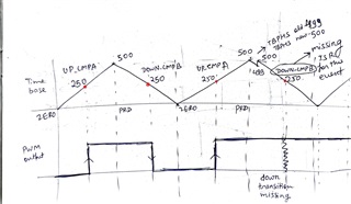
I'm using F28379D controller for my application of controlling two full bridge converter. In this, I am using 4-EPWMs. Im keeping EPWM1 as master and which will generate syncout event when EPWM_SYNC_OUT_PULSE_ON_COUNTER_ZERO. The problem I'm facing was (focusing only on EPWM3), when I'm changing the phase shift value from 0 to 1 in TBPHS of EPWM3, it's missing one entire cycle of pulse. I have tried with many variety of values and found that it happens only when I shift from 0 to other values. I have read some E2E forums and TRM, but didn't getting proper solution for this. The configuration which I've used in EPWM3 was given below, have a look at it. Kindly provide me the solution, why it's happening and how to resolve this. Thanks
EPWM3:
//
// Set-up TBCLK
//
EPWM_setTimeEPWM3_BASEPeriod(EPWM3_BASE, EPWM_TIMER_TBPRD-1);
EPWM_setPhaseShift(EPWM3_BASE, 0U);
EPWM_setTimeEPWM3_BASECounter(EPWM3_BASE, 0U);
//
// Set Compare values
//
EPWM_setCounterCompareValue(EPWM3_BASE,
EPWM_COUNTER_COMPARE_A,
(EPWM_TIMER_TBPRD/2)-1);
EPWM_setCounterCompareValue(EPWM3_BASE,
EPWM_COUNTER_COMPARE_B,
(EPWM_TIMER_TBPRD/2)-1);
//
// Set up counter mode
//
EPWM_setTimeEPWM3_BASECounterMode(EPWM3_BASE, EPWM_COUNTER_MODE_UP);
EPWM_disablePhaseShiftLoad(EPWM3_BASE);
EPWM_setClockPrescaler(EPWM3_BASE,
EPWM_CLOCK_DIVIDER_1,
EPWM_HSCLOCK_DIVIDER_1);
//
// Set up shadowing
//
EPWM_setCounterCompareShadowLoadMode(EPWM3_BASE,
EPWM_COUNTER_COMPARE_A,
EPWM_COMP_LOAD_ON_CNTR_ZERO);
EPWM_setCounterCompareShadowLoadMode(EPWM3_BASE,
EPWM_COUNTER_COMPARE_B,
EPWM_COMP_LOAD_ON_CNTR_ZERO);
EPWM_setDeadBandControlShadowLoadMode(EPWM3_BASE, EPWM_DB_LOAD_ON_CNTR_ZERO);
//
// Set actions
//
EPWM_setActionQualifierAction(EPWM3_BASE,
EPWM_AQ_OUTPUT_A,
EPWM_AQ_OUTPUT_HIGH,
EPWM_AQ_OUTPUT_ON_TIMEEPWM3_BASE_ZERO);
EPWM_setActionQualifierAction(EPWM3_BASE,
EPWM_AQ_OUTPUT_B,
EPWM_AQ_OUTPUT_HIGH,
EPWM_AQ_OUTPUT_ON_TIMEEPWM3_BASE_ZERO);
EPWM_setActionQualifierAction(EPWM3_BASE,
EPWM_AQ_OUTPUT_A,
EPWM_AQ_OUTPUT_LOW,
EPWM_AQ_OUTPUT_ON_TIMEEPWM3_BASE_UP_CMPA);
EPWM_setActionQualifierAction(EPWM3_BASE,
EPWM_AQ_OUTPUT_B,
EPWM_AQ_OUTPUT_LOW,
EPWM_AQ_OUTPUT_ON_TIMEEPWM3_BASE_UP_CMPB);
//
// ePWM1 SYNCO is generated on CTR=0
//
EPWM_setSyncOutPulseMode(EPWM1_BASE, EPWM_SYNC_OUT_PULSE_ON_COUNTER_ZERO);
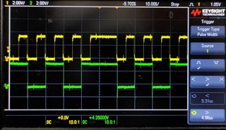
Here i've attached the missing pulse event. Yellow - EPWM3A, Green - EPWM3B both are complementry signals.
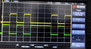
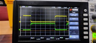
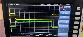
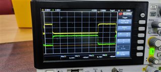
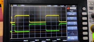
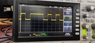
Hi Karthick,
When are updating your TBPHS value to 1? I also see that you are disabling phase shift load for EPWM3 in the initialization. You should be sure to enable phase shift loading to implement your phase shift, are you changing this in your ISR where you update TBPHS?
Best regards,
Allison
Hi, Thanks for your quick response.
Actually I'm changing the phase shift through debugging mode by directly changing the TBPHS register values. Initially it was kept running at 0-phase. Once I change its value to 1, it misses once cycle of pulse then comes to normal condition. And I'm disabling first, then enabling the Enable Phase Load function on EPWM3 after the configuring the peripheral.
//EPWM FirmWare Source File #include "can_fw.h" #include "epwm_fw.h" #include "config_fw.h" #include "driverlib.h" #include "device.h" #include "SFO_V8.h" #include "conv_fw.h" #include "sw_timer.h" #include "sdfm_fw.h" #include "cmpss.h" #define EPWM_MAX_DEADBAND_TIME 300U//4840U//4000U //This if for slow start, it will start with max DB then reduce little by little, //So that the PWM will increase slowly.Avoid capacitor Current spikes. #define EPWM_DEADBAND_STEP_SIZE 10U//10U//100U #define EPWM_CLOCK_CYCLE 10U //period in nanoSeconds #define EPWM_SHIFT_AMOUNT 7U #define EPWM_DEADBAND_VALUE(X) ((X / EPWM_CLOCK_CYCLE) << EPWM_SHIFT_AMOUNT) #define EPWM_PRIM_PW_STEP 20 #define EPWM_SEC_PW_STEP 20 #define EPWM_PHASE_SHIFT_STEP 10 #define EPWM_SHIFT_STEP_SIZE 50U #define EPWM_DEFAULT_PHASE_SHIFT 30U #define EPWM_ZERO_PHASE_SHIFT 0U #define EPWM_GPIO_GD_EN_PRI 9U #define EPWM_GPIO_GD_EN_SEC 11U #define PWM_COUNT 5 #define CHANNEL_A 1 #define CHANNEL_B 2 #define CHANNEL_AB 3 #define EPWM_TIMER_TBPRD 1000U //Macros for PWM1 #define EPWM1_TIMER_TBPRD 1000U//to be changed to 5us #define EPWM1_CMPA 500U #define EPWM1_CMPB 500U //Macros for PWM2 #define EPWM2_TIMER_TBPRD 1000U//to be changed to 5us #define EPWM2_CMPA 500U #define EPWM2_CMPB 500U //Macros for PWM3 #define EPWM3_TIMER_TBPRD 1000U//300U #define EPWM3_CMPA 500U//150U #define EPWM3_CMPB 500U//150U //Macros for PWM4 #define EPWM4_TIMER_TBPRD 1000U//300U #define EPWM4_CMPA 500U//150U #define EPWM4_CMPB 500U//150U //Count Mode #define EPWM_CMP_UP 1 #define EPWM_CMP_DOWN 0 typedef struct { uint8_t updateFlag; uint8_t epwmPort; uint32_t epwmModule; uint16_t epwmPeriod; uint16_t epwmTimerIntCount; uint16_t epwmCompA; uint16_t epwmCompB; uint32_t phaseShift; uint16_t red; uint16_t fed; }Epwm_Info_t; //now typedef enum { EPWM_ENABLE_PRIMARY = 0, EPWM_ENABLE_SECONDARY, EPWM_ENABLE_BOTH, EPWM_DISABLE_PRIMARY, EPWM_DISABLE_SECONDARY, EPWM_DISABLE_BOTH, }epwm_switch_control_e; typedef enum { EPWM_IDLE, EPWM_STEADY_STATE, EPWM_TRIP_STATE, }epwm_state_e; typedef enum { PWM_NO_EVENT = 0, PWM_START, PWM_STABLE, PWM_TRIP, PWM_STOP, PWM_UPDATE_VALUES, }epwm_event_e; typedef struct { epwm_state_e state; uint16_t counter; //Counter was made to take care of slow start period to become stable uint16_t deadBand; //to keep track of DeadBand value uint16_t curr_prim_pulse_ns; //to keep track of pulse width of Primary( Btw Pwm1 and Pwm2) uint16_t curr_sec_pulse_ns; //to keep track of pulse width of Secondary( Btw Pwm3 and Pwm4) int16_t curr_phase_pri_sec_ns; //to keep track of phase shift between epwm1 and epwm3 uint16_t final_prim_pulse_ns; //to track final pulse to be achieved uint16_t final_sec_pulse_ns; //to track final pulse to be achieved int16_t final_phase_pri_sec_ns;//to track final phase to be achieved int16_t pwm1_time_base; int16_t pwm2_time_base; int16_t pwm3_time_base; int16_t pwm4_time_base; }epwm_fw_state_t; Epwm_Info_t epwmInfo[PWM_COUNT]; epwm_fw_state_t epwm_fw_state = {EPWM_IDLE, 0, EPWM_MAX_DEADBAND_TIME, EPWM_ZERO_PHASE_SHIFT}; volatile uint32_t ePWM[] = {0, EPWM1_BASE, EPWM2_BASE, EPWM3_BASE, EPWM4_BASE}; int MEP_ScaleFactor; // Global variable used by the SFO library // Result can be used for all HRPWM channels // This variable is also copied to HRMSTEP // register by SFO() function. /******************************************************** #Init *********************************************************/ void EPWM_Init(void) { uint16_t status = 0; epwm_ConfigureIOs(); // // Calling SFO() updates the HRMSTEP register with calibrated MEP_ScaleFactor. // HRMSTEP must be populated with a scale factor value prior to enabling // high resolution period control. // while(status == SFO_INCOMPLETE) { status = SFO(); if(status == SFO_ERROR) { ESTOP0; } // steps/coarse step exceeds maximum of 255. } epwm_PreConfigureChannel(EPWM1_BASE); epwm_PreConfigureChannel(EPWM2_BASE); epwm_PreConfigureChannel(EPWM3_BASE); epwm_PreConfigureChannel(EPWM4_BASE); // // Interrupts that are used in this example are re-mapped to ISR functions // found within this file. // Interrupt_register(INT_EPWM1_TZ, &epwm1TZISR); Interrupt_register(INT_EPWM2_TZ, &epwm2TZISR); Interrupt_register(INT_EPWM3_TZ, &epwm3TZISR); Interrupt_register(INT_EPWM4_TZ, &epwm4TZISR); // // Assign the interrupt service routines to ePWM interrupts // Interrupts commented to avoid frequent interruption // earlier used for single pulse // Interrupt_register(INT_EPWM1, &epwm1_isr); // Interrupt_register(INT_EPWM2, &epwm2_isr); // Interrupt_register(INT_EPWM3, &epwm3_isr); // Interrupt_register(INT_EPWM4, &epwm4_isr); // Disable sync(Freeze clock to PWM as well). GTBCLKSYNC is applicable // only for multiple core devices. Uncomment the below statement if // applicable. // SysCtl_disablePeripheral(SYSCTL_PERIPH_CLK_TBCLKSYNC); epwm_TripZoneInit(); //Initializing with Maximum Dead-band Time epwm_fw_state.deadBand = EPWM_MAX_DEADBAND_TIME; // // Initialize PWM1 without phase shift as master // epwm_ConfigureChannel(EPWM1_BASE); epwm_HRPWM_DeadBand(1, EPWM_DEADBAND_VALUE(epwm_fw_state.deadBand)); // // Initialize PWM2 with phase shift of 300 TBCLKs // epwm_ConfigureChannel(EPWM2_BASE); EPWM_selectPeriodLoadEvent(EPWM2_BASE, EPWM_SHADOW_LOAD_MODE_SYNC); epwm_HRPWM_DeadBand(2, EPWM_DEADBAND_VALUE(epwm_fw_state.deadBand)); // // Initialize PWM3 with phase shift of 600 TBCLKs // epwm_ConfigureChannel(EPWM3_BASE); EPWM_selectPeriodLoadEvent(EPWM3_BASE, EPWM_SHADOW_LOAD_MODE_SYNC); epwm_HRPWM_DeadBand(3, EPWM_DEADBAND_VALUE(epwm_fw_state.deadBand)); // // Initialize PWM4 with phase shift of 900 TBCLKs // epwm_ConfigureChannel(EPWM4_BASE); EPWM_selectPeriodLoadEvent(EPWM4_BASE, EPWM_SHADOW_LOAD_MODE_SYNC); epwm_HRPWM_DeadBand(4, EPWM_DEADBAND_VALUE(epwm_fw_state.deadBand)); // // ePWM1 SYNCO is generated on CTR=0 // EPWM_setSyncOutPulseMode(EPWM1_BASE, EPWM_SYNC_OUT_PULSE_ON_COUNTER_ZERO); // // ePWM2 uses the ePWM 1 SYNCO as its SYNCIN. // ePWM2 SYNCO is generated from its SYNCIN, which is ePWM1 SYNCO // EPWM_setSyncOutPulseMode(EPWM2_BASE, EPWM_SYNC_OUT_PULSE_ON_EPWMxSYNCIN); // // ePWM4 uses the ePWM 1 SYNCO as its SYNCIN. // SysCtl_setSyncInputConfig(SYSCTL_SYNC_IN_EPWM4, SYSCTL_SYNC_IN_SRC_EPWM1SYNCOUT); // // Enable all phase shifts. // EPWM_enablePhaseShiftLoad(EPWM2_BASE); EPWM_enablePhaseShiftLoad(EPWM3_BASE); EPWM_enablePhaseShiftLoad(EPWM4_BASE); //to force pwms in tripped state at the time of initialization //uncomment below code to run pwms after reset EPWM_forceTripZoneEvent(EPWM1_BASE,EPWM_TZ_FORCE_EVENT_OST); EPWM_forceTripZoneEvent(EPWM2_BASE,EPWM_TZ_FORCE_EVENT_OST); EPWM_forceTripZoneEvent(EPWM3_BASE,EPWM_TZ_FORCE_EVENT_OST); EPWM_forceTripZoneEvent(EPWM4_BASE,EPWM_TZ_FORCE_EVENT_OST); // // Enable sync and clock to PWM // SysCtl_enablePeripheral(SYSCTL_PERIPH_CLK_TBCLKSYNC); epwm_Post_Init(); //timer used for calling mep calibration function sw_timer_start(CONV_FW_MEP_CAL_TIMER_INDEX, CONV_FW_MED_CAL_TIMER_PERIOD_MS, SW_TIMER_PERIODIC); //timer used for updating the values into current status of pheripheral sw_timer_start(CONV_FW_PWM_UPDATE_TIMER_INDEX, CONV_FW_PWM_UPDATE_TIMER_PERIOD_MS, SW_TIMER_PERIODIC); } // // Configure Output pins and Mux settings for 8 PWMs for gate driver control // static void epwm_ConfigureIOs(void) { #ifdef _CONTROL_CARD //Primary side gate driver IN-/enable pin configuration as GPIO GPIO_setPadConfig(EPWM_GPIO_GD_EN_PRI, GPIO_PIN_TYPE_STD); GPIO_setDirectionMode(EPWM_GPIO_GD_EN_PRI, GPIO_DIR_MODE_OUT); epwm_Disable_Drivers_Primary(); //Primary side gate driver IN-/enable pin configuration as GPIO GPIO_setPadConfig(EPWM_GPIO_GD_EN_SEC, GPIO_PIN_TYPE_STD); GPIO_setDirectionMode(EPWM_GPIO_GD_EN_SEC, GPIO_DIR_MODE_OUT); epwm_Disable_Drivers_Secondary(); #endif /* _CONTROL_CARD */ // // EPWM1 -> EPWM1 Pinmux // GPIO_setPinConfig(GPIO_0_EPWM1A); GPIO_setPadConfig(1, GPIO_PIN_TYPE_STD); GPIO_setQualificationMode(1, GPIO_QUAL_SYNC); GPIO_setPinConfig(GPIO_1_EPWM1B); GPIO_setPadConfig(2, GPIO_PIN_TYPE_STD); GPIO_setQualificationMode(2, GPIO_QUAL_SYNC); // // EPWM2 -> EPWM2 Pinmux // GPIO_setPinConfig(GPIO_2_EPWM2A); GPIO_setPadConfig(3, GPIO_PIN_TYPE_STD); GPIO_setQualificationMode(3, GPIO_QUAL_SYNC); GPIO_setPinConfig(GPIO_3_EPWM2B); GPIO_setPadConfig(4, GPIO_PIN_TYPE_STD); GPIO_setQualificationMode(4, GPIO_QUAL_SYNC); // // EPWM3 -> EPWM3 Pinmux // GPIO_setPinConfig(GPIO_4_EPWM3A); GPIO_setPadConfig(5, GPIO_PIN_TYPE_STD); GPIO_setQualificationMode(5, GPIO_QUAL_SYNC); GPIO_setPinConfig(GPIO_5_EPWM3B); GPIO_setPadConfig(6, GPIO_PIN_TYPE_STD); GPIO_setQualificationMode(6, GPIO_QUAL_SYNC); // // EPWM4 -> EPWM4 Pinmux // GPIO_setPinConfig(GPIO_6_EPWM4A); GPIO_setPadConfig(7, GPIO_PIN_TYPE_STD); GPIO_setQualificationMode(7, GPIO_QUAL_SYNC); GPIO_setPinConfig(GPIO_7_EPWM4B); GPIO_setPadConfig(8, GPIO_PIN_TYPE_STD); GPIO_setQualificationMode(8, GPIO_QUAL_SYNC); } static void epwm_PreConfigureChannel(uint32_t base) { EPWM_setClockPrescaler(base, EPWM_CLOCK_DIVIDER_1, EPWM_HSCLOCK_DIVIDER_1); EPWM_setTimeBasePeriod(base, 0); EPWM_setTimeBaseCounter(base, 0); EPWM_setTimeBaseCounterMode(base, EPWM_COUNTER_MODE_STOP_FREEZE); EPWM_disablePhaseShiftLoad(base); EPWM_setPhaseShift(base, 0); EPWM_setCounterCompareValue(base, EPWM_COUNTER_COMPARE_A, 0); EPWM_setCounterCompareShadowLoadMode(base, EPWM_COUNTER_COMPARE_A, EPWM_COMP_LOAD_ON_CNTR_ZERO); EPWM_setCounterCompareValue(base, EPWM_COUNTER_COMPARE_B, 0); EPWM_setCounterCompareShadowLoadMode(base, EPWM_COUNTER_COMPARE_B, EPWM_COMP_LOAD_ON_CNTR_ZERO); EPWM_setActionQualifierAction(base, EPWM_AQ_OUTPUT_A, EPWM_AQ_OUTPUT_NO_CHANGE, EPWM_AQ_OUTPUT_ON_TIMEBASE_ZERO); EPWM_setActionQualifierAction(base, EPWM_AQ_OUTPUT_A, EPWM_AQ_OUTPUT_NO_CHANGE, EPWM_AQ_OUTPUT_ON_TIMEBASE_PERIOD); EPWM_setActionQualifierAction(base, EPWM_AQ_OUTPUT_A, EPWM_AQ_OUTPUT_NO_CHANGE, EPWM_AQ_OUTPUT_ON_TIMEBASE_UP_CMPA); EPWM_setActionQualifierAction(base, EPWM_AQ_OUTPUT_A, EPWM_AQ_OUTPUT_NO_CHANGE, EPWM_AQ_OUTPUT_ON_TIMEBASE_DOWN_CMPA); EPWM_setActionQualifierAction(base, EPWM_AQ_OUTPUT_A, EPWM_AQ_OUTPUT_NO_CHANGE, EPWM_AQ_OUTPUT_ON_TIMEBASE_UP_CMPB); EPWM_setActionQualifierAction(base, EPWM_AQ_OUTPUT_A, EPWM_AQ_OUTPUT_NO_CHANGE, EPWM_AQ_OUTPUT_ON_TIMEBASE_DOWN_CMPB); EPWM_setActionQualifierAction(base, EPWM_AQ_OUTPUT_B, EPWM_AQ_OUTPUT_NO_CHANGE, EPWM_AQ_OUTPUT_ON_TIMEBASE_ZERO); EPWM_setActionQualifierAction(base, EPWM_AQ_OUTPUT_B, EPWM_AQ_OUTPUT_NO_CHANGE, EPWM_AQ_OUTPUT_ON_TIMEBASE_PERIOD); EPWM_setActionQualifierAction(base, EPWM_AQ_OUTPUT_B, EPWM_AQ_OUTPUT_NO_CHANGE, EPWM_AQ_OUTPUT_ON_TIMEBASE_UP_CMPA); EPWM_setActionQualifierAction(base, EPWM_AQ_OUTPUT_B, EPWM_AQ_OUTPUT_NO_CHANGE, EPWM_AQ_OUTPUT_ON_TIMEBASE_DOWN_CMPA); EPWM_setActionQualifierAction(base, EPWM_AQ_OUTPUT_B, EPWM_AQ_OUTPUT_NO_CHANGE, EPWM_AQ_OUTPUT_ON_TIMEBASE_UP_CMPB); EPWM_setActionQualifierAction(base, EPWM_AQ_OUTPUT_B, EPWM_AQ_OUTPUT_NO_CHANGE, EPWM_AQ_OUTPUT_ON_TIMEBASE_DOWN_CMPB); } static void epwm_TripZoneInit() { //This is tripping for EPWM1 with Filter3 Using Mux20 // //XBAR configuration for mapping SDFM threshold trigger event to Digital Compare submodule // //Trip Zone // //Muxing the trip4 signal to all SDFM Filter Comparators. // XBAR_setEPWMMuxConfig(XBAR_TRIP4, XBAR_EPWM_MUX16_SD1FLT1_COMPH_OR_COMPL); XBAR_enableEPWMMux(XBAR_TRIP4, XBAR_MUX16); XBAR_setEPWMMuxConfig(XBAR_TRIP4, XBAR_EPWM_MUX18_SD1FLT2_COMPH_OR_COMPL); XBAR_enableEPWMMux(XBAR_TRIP4, XBAR_MUX18); XBAR_setEPWMMuxConfig(XBAR_TRIP4, XBAR_EPWM_MUX20_SD1FLT3_COMPH_OR_COMPL); XBAR_enableEPWMMux(XBAR_TRIP4, XBAR_MUX20); XBAR_setEPWMMuxConfig(XBAR_TRIP4, XBAR_EPWM_MUX22_SD1FLT4_COMPH_OR_COMPL); XBAR_enableEPWMMux(XBAR_TRIP4, XBAR_MUX22); XBAR_setEPWMMuxConfig(XBAR_TRIP4, XBAR_EPWM_MUX00_CMPSS1_CTRIPH); XBAR_enableEPWMMux(XBAR_TRIP4, XBAR_MUX00); XBAR_setEPWMMuxConfig(XBAR_TRIP4, XBAR_EPWM_MUX02_CMPSS2_CTRIPH); XBAR_enableEPWMMux(XBAR_TRIP4, XBAR_MUX02); //////////////////////////------ EPWM1 With TRIPIN4-----////////////////////////////////////////// // // Select TRIPIN1 (INPUT XBAR INPUT1) as the source for DCAH // EPWM_selectDigitalCompareTripInput( EPWM1_BASE, EPWM_DC_TRIP_TRIPIN4, EPWM_DC_TYPE_DCAH); // // DCAEVT1 is generated when DCAH is low // EPWM_setTripZoneDigitalCompareEventCondition( EPWM1_BASE, EPWM_TZ_DC_OUTPUT_A1, EPWM_TZ_EVENT_DCXH_HIGH); // // DCAEVT1 uses the unfiltered version of DCAEVT1 // EPWM_setDigitalCompareEventSource( EPWM1_BASE, EPWM_DC_MODULE_A, EPWM_DC_EVENT_1, EPWM_DC_EVENT_SOURCE_ORIG_SIGNAL); // // DCAEVT1 is asynchronous // EPWM_setDigitalCompareEventSyncMode( EPWM1_BASE, EPWM_DC_MODULE_A, EPWM_DC_EVENT_1, EPWM_DC_EVENT_INPUT_NOT_SYNCED); // // Action on DCAEVT1 // Force the EPWMA LOW // EPWM_setTripZoneAction(EPWM1_BASE, EPWM_TZ_ACTION_EVENT_TZA, EPWM_TZ_ACTION_LOW); EPWM_setTripZoneAction(EPWM1_BASE, EPWM_TZ_ACTION_EVENT_TZB, EPWM_TZ_ACTION_LOW); EPWM_enableTripZoneInterrupt(EPWM1_BASE, EPWM_TZ_INTERRUPT_DCAEVT1); //////////////////////////------ EPWM2 With TRIPIN4-----////////////////////////////////////////// // // Select TRIPIN1 (INPUT XBAR INPUT1) as the source for DCAH // EPWM_selectDigitalCompareTripInput( EPWM2_BASE, EPWM_DC_TRIP_TRIPIN4, EPWM_DC_TYPE_DCAH); // // DCAEVT1 is generated when DCAH is low // EPWM_setTripZoneDigitalCompareEventCondition( EPWM2_BASE, EPWM_TZ_DC_OUTPUT_A1, EPWM_TZ_EVENT_DCXH_HIGH); // // DCAEVT1 uses the unfiltered version of DCAEVT1 // EPWM_setDigitalCompareEventSource( EPWM2_BASE, EPWM_DC_MODULE_A, EPWM_DC_EVENT_1, EPWM_DC_EVENT_SOURCE_ORIG_SIGNAL); // // DCAEVT1 is asynchronous // EPWM_setDigitalCompareEventSyncMode( EPWM2_BASE, EPWM_DC_MODULE_A, EPWM_DC_EVENT_1, EPWM_DC_EVENT_INPUT_NOT_SYNCED); // // Action on DCAEVT1 // Force the EPWMA LOW // EPWM_setTripZoneAction(EPWM2_BASE, EPWM_TZ_ACTION_EVENT_TZA, EPWM_TZ_ACTION_LOW); EPWM_setTripZoneAction(EPWM2_BASE, EPWM_TZ_ACTION_EVENT_TZB, EPWM_TZ_ACTION_LOW); EPWM_enableTripZoneInterrupt(EPWM2_BASE, EPWM_TZ_INTERRUPT_DCAEVT1); //////////////////////////------ EPWM3 With TRIPIN4-----////////////////////////////////////////// EPWM_selectDigitalCompareTripInput( EPWM3_BASE, EPWM_DC_TRIP_TRIPIN4, EPWM_DC_TYPE_DCAH); // // DCAEVT1 is generated when DCAH is low // EPWM_setTripZoneDigitalCompareEventCondition( EPWM3_BASE, EPWM_TZ_DC_OUTPUT_A1, EPWM_TZ_EVENT_DCXH_HIGH); // // DCAEVT1 uses the unfiltered version of DCAEVT1 // EPWM_setDigitalCompareEventSource( EPWM3_BASE, EPWM_DC_MODULE_A, EPWM_DC_EVENT_1, EPWM_DC_EVENT_SOURCE_ORIG_SIGNAL); // // DCAEVT1 is asynchronous // EPWM_setDigitalCompareEventSyncMode( EPWM3_BASE, EPWM_DC_MODULE_A, EPWM_DC_EVENT_1, EPWM_DC_EVENT_INPUT_NOT_SYNCED); // // Action on DCAEVT1 // Force the EPWMA LOW // EPWM_setTripZoneAction(EPWM3_BASE, EPWM_TZ_ACTION_EVENT_TZA, EPWM_TZ_ACTION_LOW); EPWM_setTripZoneAction(EPWM3_BASE, EPWM_TZ_ACTION_EVENT_TZB, EPWM_TZ_ACTION_LOW); EPWM_enableTripZoneInterrupt(EPWM3_BASE, EPWM_TZ_INTERRUPT_DCAEVT1); //////////////////////////------ EPWM4 With TRIPIN4-----////////////////////////////////////////// EPWM_selectDigitalCompareTripInput( EPWM4_BASE, EPWM_DC_TRIP_TRIPIN4, EPWM_DC_TYPE_DCAH); // // DCAEVT1 is generated when DCAH is low // EPWM_setTripZoneDigitalCompareEventCondition( EPWM4_BASE, EPWM_TZ_DC_OUTPUT_A1, EPWM_TZ_EVENT_DCXH_HIGH); // // DCAEVT1 uses the unfiltered version of DCAEVT1 // EPWM_setDigitalCompareEventSource( EPWM4_BASE, EPWM_DC_MODULE_A, EPWM_DC_EVENT_1, EPWM_DC_EVENT_SOURCE_ORIG_SIGNAL); // // DCAEVT1 is asynchronous // EPWM_setDigitalCompareEventSyncMode( EPWM4_BASE, EPWM_DC_MODULE_A, EPWM_DC_EVENT_1, EPWM_DC_EVENT_INPUT_NOT_SYNCED); // // Action on DCAEVT1 // Force the EPWMA LOW // EPWM_setTripZoneAction(EPWM4_BASE, EPWM_TZ_ACTION_EVENT_TZA, EPWM_TZ_ACTION_LOW); EPWM_setTripZoneAction(EPWM4_BASE, EPWM_TZ_ACTION_EVENT_TZB, EPWM_TZ_ACTION_LOW); EPWM_enableTripZoneInterrupt(EPWM4_BASE, EPWM_TZ_INTERRUPT_DCAEVT1); Interrupt_enable(INT_EPWM1_TZ); Interrupt_enable(INT_EPWM2_TZ); Interrupt_enable(INT_EPWM3_TZ); Interrupt_enable(INT_EPWM4_TZ); } // // // static void epwm_ConfigureChannel(uint32_t base) { // // Set-up TBCLK // EPWM_setTimeBasePeriod(base, EPWM_TIMER_TBPRD-1); EPWM_setPhaseShift(base, 0U); EPWM_setTimeBaseCounter(base, 0U); // // Set Compare values // EPWM_setCounterCompareValue(base, EPWM_COUNTER_COMPARE_A, (EPWM_TIMER_TBPRD/2)-1); EPWM_setCounterCompareValue(base, EPWM_COUNTER_COMPARE_B, (EPWM_TIMER_TBPRD/2)-1); // // Set up counter mode // EPWM_setTimeBaseCounterMode(base, EPWM_COUNTER_MODE_UP); EPWM_disablePhaseShiftLoad(base); EPWM_setClockPrescaler(base, EPWM_CLOCK_DIVIDER_1, EPWM_HSCLOCK_DIVIDER_1); // // Set up shadowing // EPWM_setCounterCompareShadowLoadMode(base, EPWM_COUNTER_COMPARE_A, EPWM_COMP_LOAD_ON_CNTR_ZERO); EPWM_setCounterCompareShadowLoadMode(base, EPWM_COUNTER_COMPARE_B, EPWM_COMP_LOAD_ON_CNTR_ZERO); EPWM_setDeadBandControlShadowLoadMode(base, EPWM_DB_LOAD_ON_CNTR_ZERO); // // Set actions // EPWM_setActionQualifierAction(base, EPWM_AQ_OUTPUT_A, EPWM_AQ_OUTPUT_HIGH, EPWM_AQ_OUTPUT_ON_TIMEBASE_ZERO); EPWM_setActionQualifierAction(base, EPWM_AQ_OUTPUT_B, EPWM_AQ_OUTPUT_HIGH, EPWM_AQ_OUTPUT_ON_TIMEBASE_ZERO); EPWM_setActionQualifierAction(base, EPWM_AQ_OUTPUT_A, EPWM_AQ_OUTPUT_LOW, EPWM_AQ_OUTPUT_ON_TIMEBASE_UP_CMPA); EPWM_setActionQualifierAction(base, EPWM_AQ_OUTPUT_B, EPWM_AQ_OUTPUT_LOW, EPWM_AQ_OUTPUT_ON_TIMEBASE_UP_CMPB); HRPWM_setMEPEdgeSelect(base, HRPWM_CHANNEL_A, HRPWM_MEP_CTRL_RISING_AND_FALLING_EDGE); HRPWM_setMEPControlMode(base, HRPWM_CHANNEL_A, HRPWM_MEP_DUTY_PERIOD_CTRL); HRPWM_setCounterCompareShadowLoadEvent(base, HRPWM_CHANNEL_A, HRPWM_LOAD_ON_CNTR_ZERO_PERIOD); HRPWM_setMEPEdgeSelect(base, HRPWM_CHANNEL_B, HRPWM_MEP_CTRL_RISING_AND_FALLING_EDGE); HRPWM_setMEPControlMode(base, HRPWM_CHANNEL_B, HRPWM_MEP_DUTY_PERIOD_CTRL); HRPWM_setCounterCompareShadowLoadEvent(base, HRPWM_CHANNEL_B, HRPWM_LOAD_ON_CNTR_ZERO_PERIOD); HRPWM_enableAutoConversion(base); // // Turn on high-resolution period control. // HRPWM_enablePeriodControl(base); HRPWM_enablePhaseShiftLoad(base); EPWM_forceSyncPulse(base); // // Interrupt where we will change the Compare Values // Select INT on Time base counter zero event, // Enable INT, generate INT on 1rd event // below code not being used as epwm interrupts are disabled // EPWM_setInterruptSource(base, EPWM_INT_TBCTR_ZERO); EPWM_enableInterrupt(base); EPWM_setInterruptEventCount(base, 1U); } // // // void epwm_Post_Init(void) { EPWM_enableTripZoneSignals(EPWM1_BASE, EPWM_TZ_SIGNAL_DCAEVT1); EPWM_enableTripZoneSignals(EPWM2_BASE, EPWM_TZ_SIGNAL_DCAEVT1); EPWM_enableTripZoneSignals(EPWM3_BASE, EPWM_TZ_SIGNAL_DCAEVT1); EPWM_enableTripZoneSignals(EPWM4_BASE, EPWM_TZ_SIGNAL_DCAEVT1); } /******************************************************** #DeadBand *********************************************************/ // // @fn: this will set DeadBand value with Active High RED on Both channels // @param: base contains base value for DB to set. value contains actual value to set in (DBRED:DBREDHR) // \b Note: redCount is a 21 bit value. // \b Note: For configuring DBRED = 0x4, DBREDHR = 0x1; value of // redCount = ((0x4 << 7) | 0x1) = 0x201 // static void epwm_HRPWM_DeadBand(uint8_t base, uint32_t value) { // // DO NOT Switch Output A with Output B // true - it will swap the signal , ie. it will replicate other channel's signal // false - it will produce same signal as it generates //@must - during complementary mode, these lines will set the swap mode, if we do these steps after setting up // then our output might have some problems. so do this at beginning of init. EPWM_setDeadBandOutputSwapMode(ePWM[base], EPWM_DB_OUTPUT_A, false); EPWM_setDeadBandOutputSwapMode(ePWM[base], EPWM_DB_OUTPUT_B, false); // // Use EPWMA as the input for both RED and FED // EPWM_setRisingEdgeDeadBandDelayInput(ePWM[base], EPWM_DB_INPUT_EPWMA); EPWM_setFallingEdgeDeadBandDelayInput(ePWM[base], EPWM_DB_INPUT_EPWMB); // // Set the RED and FED values // HRPWM_setRisingEdgeDelay(ePWM[base], value); HRPWM_setFallingEdgeDelay(ePWM[base], value); // // Invert only the Falling Edge delayed output (AHC) //EPWM_DB_POLARITY_ACTIVE_HIGH - It will produce same signal as mentioned DB //EPWM_DB_POLARITY_ACTIVE_LOW - It will produce complement of the signal EPWM_setDeadBandDelayPolarity(ePWM[base], EPWM_DB_RED, EPWM_DB_POLARITY_ACTIVE_HIGH); EPWM_setDeadBandDelayPolarity(ePWM[base], EPWM_DB_FED, EPWM_DB_POLARITY_ACTIVE_LOW); // // Use the delayed signals instead of the original signals // EPWM_setDeadBandDelayMode(ePWM[base], EPWM_DB_RED, true); EPWM_setDeadBandDelayMode(ePWM[base], EPWM_DB_FED, true); HRPWM_setDeadbandMEPEdgeSelect(ePWM[base], HRPWM_DB_MEP_CTRL_RED_FED); HRPWM_setRisingEdgeDelayLoadMode(ePWM[base], HRPWM_LOAD_ON_CNTR_ZERO); HRPWM_setFallingEdgeDelayLoadMode(ePWM[base], HRPWM_LOAD_ON_CNTR_ZERO); TRACE_I(EPWM_TRACE,"EPWM%d Setted FED & RED with value = %d ...\r\n",(uint32_t)base,value); } /******************************************************** #Phase Shift *********************************************************/ void Epwm_Fw_SetPhaseShifts(uint16_t priShift, int16_t pri_sec_shift, uint16_t secShift) { int16_t phase12 = priShift - epwm_fw_state.pwm1_time_base; int16_t phase13 = pri_sec_shift + phase12/2 - secShift/2; int16_t phase14 = pri_sec_shift + phase12/2 + secShift/2; if(phase12 <= 5000 && phase13 <= 5000 && phase14 <= 7500 && phase14 >= phase13) { epwm_fw_state.curr_prim_pulse_ns = priShift; epwm_fw_state.curr_sec_pulse_ns = secShift; epwm_fw_state.curr_phase_pri_sec_ns = pri_sec_shift; Epwm_Fw_SetPhase12(phase12); Epwm_Fw_SetPhase13(phase13); Epwm_Fw_SetPhase14(phase14); } } //It will alter Pulse width of Primary, //sets phase shift on EPWM2 alone (Shift Btw Pwm1 and Pwm2) void Epwm_Fw_SetPulseWidthPri(int16_t shiftValue) { int16_t pulse = shiftValue - epwm_fw_state.pwm1_time_base; int16_t phase13 = epwm_fw_state.curr_phase_pri_sec_ns + pulse/2 - epwm_fw_state.curr_sec_pulse_ns/2; int16_t phase14 = epwm_fw_state.curr_phase_pri_sec_ns + pulse/2 + epwm_fw_state.curr_sec_pulse_ns/2; if(pulse <= 5000 && phase13 <= 5000 && phase14 <= 7500) { epwm_fw_state.curr_prim_pulse_ns = pulse; Epwm_Fw_SetPhase12(shiftValue); Epwm_Fw_SetPhase13(phase13); Epwm_Fw_SetPhase14(phase14); } } //It will alter Pulse width of Secondary, //sets phase shift on Pmw3 and Pwm4 alone (Shift Btw Pwm3 and Pwm4) void Epwm_Fw_SetPulseWidthSec(int16_t shiftValue) { int16_t phase13 = epwm_fw_state.curr_phase_pri_sec_ns + epwm_fw_state.curr_prim_pulse_ns/2 - shiftValue/2; int16_t phase14 = epwm_fw_state.curr_phase_pri_sec_ns + epwm_fw_state.curr_prim_pulse_ns/2 + shiftValue/2; if(phase13 <= 5000 && phase14 <= 7500) { epwm_fw_state.curr_sec_pulse_ns = phase14 - phase13; Epwm_Fw_SetPhase13(phase13); Epwm_Fw_SetPhase14(phase14); } } //It will set the Phase shift between Primary to Secondary void Epwm_Fw_SetPhaseShift_Pri_Sec(int16_t value) { int16_t phase13 = value + epwm_fw_state.curr_prim_pulse_ns/2 - epwm_fw_state.curr_sec_pulse_ns/2; int16_t phase14 = value + epwm_fw_state.curr_prim_pulse_ns/2 + epwm_fw_state.curr_sec_pulse_ns/2; if(phase13 <= 5000 && phase14 <= 7500 && phase14 >= phase13) { epwm_fw_state.curr_phase_pri_sec_ns = value; Epwm_Fw_SetPhase13(phase13); Epwm_Fw_SetPhase14(phase14); } } //It will set Phase shift on PWM2 w.r.t PWM1 void Epwm_Fw_SetPhase12(int16_t value) { // epwm_fw_state.pwm2_time_base = value; uint32_t shift2Count = (EPWM_TIMER_TBPRD - (value/10))%EPWM_TIMER_TBPRD; uint8_t shift2CountHr = 0; shift2Count <<= 8; shift2Count += shift2CountHr; // HRPWM_setPhaseShift(EPWM2_BASE, shift2Count); epwmInfo[2].phaseShift = shift2Count; epwmInfo[2].updateFlag = TRUE; } //It will set Phase shift on PWM3 w.r.t PWM1 void Epwm_Fw_SetPhase13(int16_t value) { epwm_fw_state.pwm3_time_base = value; uint32_t shift3Count = (EPWM_TIMER_TBPRD - (value/10))%EPWM_TIMER_TBPRD; uint8_t shift3CountHr = 0; shift3Count <<= 8; shift3Count += shift3CountHr; // HRPWM_setPhaseShift(EPWM3_BASE, shift3Count); epwmInfo[3].phaseShift = shift3Count; epwmInfo[3].updateFlag = TRUE; } //It will set Phase shift on PWM4 w.r.t PWM1 void Epwm_Fw_SetPhase14(int16_t value) { epwm_fw_state.pwm4_time_base = value; uint32_t shift4Count = (EPWM_TIMER_TBPRD - (value/10))%EPWM_TIMER_TBPRD; uint8_t shift4CountHr = 0; shift4Count <<= 8; shift4Count += shift4CountHr; // HRPWM_setPhaseShift(EPWM4_BASE, shift4Count); epwmInfo[4].phaseShift = shift4Count; epwmInfo[4].updateFlag = TRUE; } //todo - implement using soft timer void Epwm_Fw_mepCalibration(void) { uint16_t status = SFO(); // in background, MEP calibration module // continuously updates MEP_ScaleFactor if (sw_timer_process(CONV_FW_MEP_CAL_TIMER_INDEX) == 1) { if (status == 2) { ESTOP0; // SFO function returns 2 if an error occurs & # // of MEP steps/coarse step } } } void Conv_Fw_UpdateValues() { Epwm_Fw_ReadValues(epwm_values); if((epwm_values[2].updateFlag && epwm_values[3].updateFlag && epwm_values[4].updateFlag) == TRUE) { HWREG(EPWM2_BASE + HRPWM_O_TBPHS) = epwm_values[2].phaseShift << 8U; HWREG(EPWM3_BASE + HRPWM_O_TBPHS) = epwm_values[3].phaseShift << 8U; HWREG(EPWM4_BASE + HRPWM_O_TBPHS) = epwm_values[4].phaseShift << 8U; } } // // epwm1TZISR - ePWM1 TZ ISR // __interrupt void epwm1TZISR(void) { // // re-enable the interrupts // EPWM_clearTripZoneFlag(EPWM1_BASE, EPWM_TZ_INTERRUPT | EPWM_TZ_FLAG_DCAEVT1); // // Uncomment the below lines of code to re-enable // the interrupts and the ePWM output if using one-shot // Below interrupt to be handled by application // todo - implement callback to application // EPWM_clearTripZoneFlag(EPWM1_BASE, EPWM_TZ_FLAG_OST | EPWM_TZ_INTERRUPT | EPWM_TZ_FLAG_DCAEVT1); // // Acknowledge this interrupt to receive more interrupts from group 2.3 // Interrupt_clearACKGroup(INTERRUPT_ACK_GROUP2); } // // epwm2TZISR - ePWM2 TZ ISR // __interrupt void epwm2TZISR(void) { // // // Uncomment the below lines of code to re-enable the interrupts // // EPWM_clearTripZoneFlag(EPWM2_BASE, EPWM_TZ_INTERRUPT | EPWM_TZ_FLAG_DCAEVT1); // // // // // Uncomment the below lines of code to re-enable // // the interrupts and the ePWM output if using one-shot // // // EPWM_clearTripZoneFlag(EPWM2_BASE, EPWM_TZ_FLAG_OST | EPWM_TZ_INTERRUPT | EPWM_TZ_FLAG_DCAEVT1); // // // // // Acknowledge this interrupt to receive more interrupts from group 2.3 // Interrupt_clearACKGroup(INTERRUPT_ACK_GROUP2); } // // epwm3TZISR - ePWM1 TZ ISR // __interrupt void epwm3TZISR(void) { // // // Uncomment the below lines of code to re-enable the interrupts // // EPWM_clearTripZoneFlag(EPWM3_BASE, EPWM_TZ_INTERRUPT | EPWM_TZ_FLAG_DCAEVT1); // // // // // Uncomment the below lines of code to re-enable // // the interrupts and the ePWM output if using one-shot // // // EPWM_clearTripZoneFlag(EPWM3_BASE, EPWM_TZ_FLAG_OST | EPWM_TZ_INTERRUPT | EPWM_TZ_FLAG_DCAEVT1); // // // // // Acknowledge this interrupt to receive more interrupts from group 2.3 // Interrupt_clearACKGroup(INTERRUPT_ACK_GROUP2); } // // epwm4TZISR - ePWM1 TZ ISR // __interrupt void epwm4TZISR(void) { // // // Uncomment the below lines of code to re-enable the interrupts // // EPWM_clearTripZoneFlag(EPWM4_BASE, EPWM_TZ_INTERRUPT | EPWM_TZ_FLAG_DCAEVT1); // // // // // Uncomment the below lines of code to re-enable // // the interrupts and the ePWM output if using one-shot // // // EPWM_clearTripZoneFlag(EPWM4_BASE, EPWM_TZ_FLAG_OST | EPWM_TZ_INTERRUPT | EPWM_TZ_FLAG_DCAEVT1); // // // // // Acknowledge this interrupt to receive more interrupts from group 2.3 // Interrupt_clearACKGroup(INTERRUPT_ACK_GROUP2); } // // epwm1_isr - ePWM 1 _isr // __interrupt void epwm1_isr(void) //ISR generated for every time period (10uS) { // // Clear INT flag for this timer // EPWM_clearEventTriggerInterruptFlag(EPWM1_BASE); // // Acknowledge interrupt group // Interrupt_clearACKGroup(INTERRUPT_ACK_GROUP3); } // // epwm2_isr - ePWM 2 _isr // __interrupt void epwm2_isr(void) { // // Clear INT flag for this timer // EPWM_clearEventTriggerInterruptFlag(EPWM2_BASE); // // Acknowledge interrupt group // Interrupt_clearACKGroup(INTERRUPT_ACK_GROUP3); } // // epwm3_isr - ePWM 3 _isr // __interrupt void epwm3_isr(void) { // // Clear INT flag for this timer // EPWM_clearEventTriggerInterruptFlag(EPWM3_BASE); // // Acknowledge interrupt group // Interrupt_clearACKGroup(INTERRUPT_ACK_GROUP3); } // // epwm4_isr - ePWM 4 _isr // __interrupt void epwm4_isr(void) { // // Clear INT flag for this timer // EPWM_clearEventTriggerInterruptFlag(EPWM4_BASE); // // Acknowledge interrupt group // Interrupt_clearACKGroup(INTERRUPT_ACK_GROUP3); } void Epwm_Fw_StepIncPriPulse(void) { volatile int16_t pulse = 20 + epwm_fw_state.final_prim_pulse_ns; if(pulse <= 5000) { Epwm_Fw_SetPriPulseFinal(pulse); // Epwm_Fw_SetPulseWidthPri(pulse); } } void Epwm_Fw_StepDecPriPulse(void) { int16_t pulse = epwm_fw_state.final_prim_pulse_ns; if(pulse >= 0) { Epwm_Fw_SetPriPulseFinal(pulse); // Epwm_Fw_SetPulseWidthPri(pulse); } } void Epwm_Fw_StepIncSecPulse(void) { int16_t pulse = 20 + epwm_fw_state.final_sec_pulse_ns; if(pulse <= 5000) { Epwm_Fw_SetSecPulseFinal(pulse); // Epwm_Fw_SetPulseWidthSec(pulse); } } void Epwm_Fw_StepDecSecPulse(void) { int16_t pulse = epwm_fw_state.final_sec_pulse_ns; if(pulse >= 0) { Epwm_Fw_SetSecPulseFinal(pulse); // Epwm_Fw_SetPulseWidthSec(pulse); } } //While changing phase shift, first call secondary pulse width function, then change phase. void Epwm_Fw_StepIncPhase(void) { int16_t phase = epwm_fw_state.final_phase_pri_sec_ns + 10; if(phase <= 2500) { Epwm_Fw_Set_Pri_Sec_PhaseFinal(phase); // Epwm_Fw_SetPhaseShift_Pri_Sec(phase); } } void Epwm_Fw_StepDecPhase(void) { int16_t phase = epwm_fw_state.final_phase_pri_sec_ns - 10; if(phase >= 0) { Epwm_Fw_Set_Pri_Sec_PhaseFinal(phase); // Epwm_Fw_SetPhaseShift_Pri_Sec(phase); } } void Epwm_Fw_SetDeadBandAll(uint16_t value) { uint8_t base = 0; for(base = 1; base <= PWM_COUNT; base++) { Epwm_Fw_SetRED(base, value); Epwm_Fw_SetFED(base, value); } } void Epwm_Fw_StepIncAll(void) { int16_t value12 = epwm_fw_state.final_prim_pulse_ns + EPWM_PRIM_PW_STEP; int16_t value14 = epwm_fw_state.final_sec_pulse_ns + EPWM_SEC_PW_STEP; int16_t value13 = epwm_fw_state.final_phase_pri_sec_ns + EPWM_PHASE_SHIFT_STEP; if((value12 <= 5000) && (value13 <= 2500 && value13 >= EPWM_DEFAULT_PHASE_SHIFT) && (value14 <= 5000)) { Epwm_Fw_Set_SetPhaseShiftsFinal(value12,value13,value14); //will set all values in final value struct } } void Epwm_Fw_StepDecAll(void) { int16_t value12 = epwm_fw_state.final_prim_pulse_ns - EPWM_PRIM_PW_STEP; int16_t value14 = epwm_fw_state.final_sec_pulse_ns - EPWM_SEC_PW_STEP; int16_t value13 = epwm_fw_state.final_phase_pri_sec_ns - EPWM_PHASE_SHIFT_STEP; if((value12 <= 5000) && (value13 <= 2500 && value13 >= EPWM_DEFAULT_PHASE_SHIFT) && (value14 <= 5000)) { Epwm_Fw_Set_SetPhaseShiftsFinal(value12,value13,value14); //will set all values in final value struct } } void Epwm_Fw_StepIncDeadBand(void) { int16_t value = epwm_fw_state.deadBand; value += 10; if(value <= 500) { Epwm_Fw_SetDeadBandAll(value); } } void Epwm_Fw_StepDecDeadBand(void) { int16_t value = epwm_fw_state.deadBand; value -= 10; if(value >= 150) { Epwm_Fw_SetDeadBandAll(value); } } void Epwm_Fw_Read(uint8_t* buff) { buff[2] = epwm_fw_state.curr_prim_pulse_ns >> 8; buff[3] = epwm_fw_state.curr_prim_pulse_ns & 0x00FF; buff[4] = epwm_fw_state.curr_phase_pri_sec_ns >> 8; buff[5] = epwm_fw_state.curr_phase_pri_sec_ns & 0x00FF; buff[6] = epwm_fw_state.curr_sec_pulse_ns >> 8; buff[7] = epwm_fw_state.curr_sec_pulse_ns & 0x00FF; } int16_t Epwm_Fw_GetPulseWidthPri() { return epwm_fw_state.curr_prim_pulse_ns; } int16_t Epwm_Fw_GetPulseWidthSec() { return epwm_fw_state.curr_sec_pulse_ns; } int16_t Epwm_Fw_GetPhaseShift() { return epwm_fw_state.curr_phase_pri_sec_ns; } void Epwm_Fw_ReadValues(Epwm_Values_t epwm_values[]) { epwm_values[2].phaseShift = epwmInfo[2].phaseShift; epwm_values[2].updateFlag = epwmInfo[2].updateFlag; epwmInfo[2].updateFlag = FALSE; epwm_values[3].phaseShift = epwmInfo[3].phaseShift; epwm_values[3].updateFlag = epwmInfo[3].updateFlag; epwmInfo[3].updateFlag = FALSE; epwm_values[4].phaseShift = epwmInfo[4].phaseShift; epwm_values[4].updateFlag = epwmInfo[4].updateFlag; epwmInfo[4].updateFlag = FALSE; } void Epwm_Fw_SetPhaseAll(uint16_t pri_pw, uint16_t sec_pw, uint16_t pri_sec_phase) { epwm_fw_state.final_prim_pulse_ns = pri_pw; epwm_fw_state.final_sec_pulse_ns = sec_pw; epwm_fw_state.final_phase_pri_sec_ns = pri_sec_phase; } void Epwm_Fw_SetPriPulseFinal(uint16_t pri_pw) { epwm_fw_state.final_prim_pulse_ns = pri_pw; } void Epwm_Fw_SetSecPulseFinal(uint16_t sec_pw) { epwm_fw_state.final_sec_pulse_ns = sec_pw; } void Epwm_Fw_Set_Pri_Sec_PhaseFinal(int16_t pri_sec_phase) { epwm_fw_state.final_phase_pri_sec_ns = pri_sec_phase; } //will update all final phase shift variables void Epwm_Fw_Set_SetPhaseShiftsFinal(uint16_t pri_pw, int16_t pri_sec_phase, uint16_t sec_pw) { epwm_fw_state.final_prim_pulse_ns = pri_pw; epwm_fw_state.final_sec_pulse_ns = sec_pw; epwm_fw_state.final_phase_pri_sec_ns = pri_sec_phase; } //to update all phase values to current status variables in struct void Epwm_Fw_UpdatePhase(void) { int8_t pri_step = 0, sec_step = 0, phase = 0; uint8_t updateFlag = 0; int16_t priPulse = epwm_fw_state.curr_prim_pulse_ns; int16_t secPulse = epwm_fw_state.curr_sec_pulse_ns; int16_t pri_sec_phase = epwm_fw_state.curr_phase_pri_sec_ns; if(epwm_fw_state.final_prim_pulse_ns != priPulse) { updateFlag = 1; //will check when final value is more than next step of current value if(epwm_fw_state.final_prim_pulse_ns > priPulse + EPWM_PRIM_PW_STEP) { pri_step += EPWM_PRIM_PW_STEP; } //will check when final value is less than next step of current value else if(epwm_fw_state.final_prim_pulse_ns < priPulse - EPWM_PRIM_PW_STEP) { pri_step -= EPWM_PRIM_PW_STEP; } //when step value is larger than difference between final and current else { pri_step = epwm_fw_state.final_prim_pulse_ns - priPulse; } if (priPulse + pri_step >= 0 && priPulse <= 5000) { // Epwm_Fw_SetPulseWidthPri(priPulse + pri_step); priPulse += pri_step; } else { /* error */ } } if(epwm_fw_state.final_sec_pulse_ns != epwm_fw_state.curr_sec_pulse_ns) { updateFlag = 1; //will check when final value is more than next step of current value if(epwm_fw_state.final_sec_pulse_ns > secPulse + EPWM_SEC_PW_STEP) { sec_step += EPWM_SEC_PW_STEP; } //will check when final value is less than next step of current value else if(epwm_fw_state.final_sec_pulse_ns < secPulse - EPWM_SEC_PW_STEP) { sec_step -= EPWM_SEC_PW_STEP; } //when the step value is larger than difference between final and current else { sec_step = epwm_fw_state.final_sec_pulse_ns - secPulse; } if (secPulse + sec_step >= 0 && secPulse <= 5000) { // Epwm_Fw_SetPulseWidthSec(secPulse + sec_step); secPulse += sec_step; } else { /* error */ } } if(epwm_fw_state.final_phase_pri_sec_ns != pri_sec_phase) { updateFlag = 1; //will check when final value is more than next step of current value if(epwm_fw_state.final_phase_pri_sec_ns > pri_sec_phase + EPWM_PHASE_SHIFT_STEP) { phase += EPWM_PHASE_SHIFT_STEP; } //will check when final value is less than next step of current value else if(epwm_fw_state.final_phase_pri_sec_ns < pri_sec_phase - EPWM_PHASE_SHIFT_STEP) { phase -= EPWM_PHASE_SHIFT_STEP; } //when the step change is larger than the difference between final and current else { phase = epwm_fw_state.final_phase_pri_sec_ns - pri_sec_phase; } if (pri_sec_phase + phase >= 0 && pri_sec_phase <= 2500) { // Epwm_Fw_SetPhaseShift_Pri_Sec(pri_sec_phase + phase); pri_sec_phase += phase; } else { /* error */ } } if(updateFlag == TRUE) { Epwm_Fw_SetPhaseShifts(priPulse, pri_sec_phase, secPulse); } }
Hi Karthick,
Thanks for sharing your .c code; I see you are using HRPWM as well now. It looks like you are setting the EPWM modules to be in up-count while implementing HR deadband module, is that correct? There is a note in the device TRM section 15.14.1.6 Deadband High-Resolution Operation that states "In up-count mode, the dead-band module is not available when any high-resolution mode is enabled." So I would recommend switching to up-down count mode instead for this application if you are not doing so. There is also another note in section 15.7.2 Dead-band Submodule Additional Operating Modes stating "High-resolution dead-band RED and FED requires Half-Cycle clocking mode (DBCTL[HALFCYCLE] = 1)", so please look into this as well. If you are going to use up-down count, you should also ensure that if you are using HR time base period control, CMPA/B must have shadow loading enabled for when 'TBCTR = 0 or PRD'.
Let me know if I am misunderstanding your program so far or if you need clarification here as well.
Best Regards,
Allison
Hi, Thanks for the reply.
I've configured as HRPWM in my code, but I'm not using any HRPWM functionalities. But, however this time I've disabled all HRPWM from the code and checked the PWMs. But, I'm facing the same issue this time too. My observation was, when doing in debugger mode. When, I'm changing the TBPHS from higher value to lower value, I'm observed there's a missing of pulse, with their difference (High_value - Low_value). I've share some images with changing phase shift from different values. Can you please check what I'm doing wrong and suggest a proper way of doing. I've attached the new .C code.
//EPWM FirmWare Source File #include "can_fw.h" #include "epwm_fw.h" #include "config_fw.h" #include "driverlib.h" #include "device.h" #include "SFO_V8.h" #include "conv_fw.h" #include "sw_timer.h" #include "sdfm_fw.h" #include "cmpss.h" #define EPWM_MAX_DEADBAND_TIME 300U//4840U//4000U //This if for slow start, it will start with max DB then reduce little by little, //So that the PWM will increase slowly.Avoid capacitor Current spikes. #define EPWM_DEADBAND_STEP_SIZE 10U//10U//100U #define EPWM_CLOCK_CYCLE 10U //period in nanoSeconds #define EPWM_SHIFT_AMOUNT 7U #define EPWM_DEADBAND_VALUE(X) ((X / EPWM_CLOCK_CYCLE) << EPWM_SHIFT_AMOUNT) #define EPWM_PRIM_PW_STEP 20 #define EPWM_SEC_PW_STEP 20 #define EPWM_PHASE_SHIFT_STEP 10 #define EPWM_SHIFT_STEP_SIZE 50U #define EPWM_DEFAULT_PHASE_SHIFT 30U #define EPWM_ZERO_PHASE_SHIFT 0U #define EPWM_GPIO_GD_EN_PRI 9U #define EPWM_GPIO_GD_EN_SEC 11U #define PWM_COUNT 5 #define CHANNEL_A 1 #define CHANNEL_B 2 #define CHANNEL_AB 3 #define EPWM_TIMER_TBPRD 1000U //Macros for PWM1 #define EPWM1_TIMER_TBPRD 1000U//to be changed to 5us #define EPWM1_CMPA 500U #define EPWM1_CMPB 500U //Macros for PWM2 #define EPWM2_TIMER_TBPRD 1000U//to be changed to 5us #define EPWM2_CMPA 500U #define EPWM2_CMPB 500U //Macros for PWM3 #define EPWM3_TIMER_TBPRD 1000U//300U #define EPWM3_CMPA 500U//150U #define EPWM3_CMPB 500U//150U //Macros for PWM4 #define EPWM4_TIMER_TBPRD 1000U//300U #define EPWM4_CMPA 500U//150U #define EPWM4_CMPB 500U//150U //Count Mode #define EPWM_CMP_UP 1 #define EPWM_CMP_DOWN 0 typedef struct { uint8_t updateFlag; uint8_t epwmPort; uint32_t epwmModule; uint16_t epwmPeriod; uint16_t epwmTimerIntCount; uint16_t epwmCompA; uint16_t epwmCompB; uint32_t phaseShift; uint16_t red; uint16_t fed; }Epwm_Info_t; //now typedef enum { EPWM_ENABLE_PRIMARY = 0, EPWM_ENABLE_SECONDARY, EPWM_ENABLE_BOTH, EPWM_DISABLE_PRIMARY, EPWM_DISABLE_SECONDARY, EPWM_DISABLE_BOTH, }epwm_switch_control_e; typedef enum { EPWM_IDLE, EPWM_STEADY_STATE, EPWM_TRIP_STATE, }epwm_state_e; typedef enum { PWM_NO_EVENT = 0, PWM_START, PWM_STABLE, PWM_TRIP, PWM_STOP, PWM_UPDATE_VALUES, }epwm_event_e; typedef struct { epwm_state_e state; uint16_t counter; //Counter was made to take care of slow start period to become stable uint16_t deadBand; //to keep track of DeadBand value uint16_t curr_prim_pulse_ns; //to keep track of pulse width of Primary( Btw Pwm1 and Pwm2) uint16_t curr_sec_pulse_ns; //to keep track of pulse width of Secondary( Btw Pwm3 and Pwm4) int16_t curr_phase_pri_sec_ns; //to keep track of phase shift between epwm1 and epwm3 uint16_t final_prim_pulse_ns; //to track final pulse to be achieved uint16_t final_sec_pulse_ns; //to track final pulse to be achieved int16_t final_phase_pri_sec_ns;//to track final phase to be achieved int16_t pwm1_time_base; int16_t pwm2_time_base; int16_t pwm3_time_base; int16_t pwm4_time_base; }epwm_fw_state_t; Epwm_Info_t epwmInfo[PWM_COUNT]; epwm_fw_state_t epwm_fw_state = {EPWM_IDLE, 0, EPWM_MAX_DEADBAND_TIME, EPWM_ZERO_PHASE_SHIFT}; volatile uint32_t ePWM[] = {0, EPWM1_BASE, EPWM2_BASE, EPWM3_BASE, EPWM4_BASE}; int MEP_ScaleFactor; // Global variable used by the SFO library // Result can be used for all HRPWM channels // This variable is also copied to HRMSTEP // register by SFO() function. /******************************************************** #Init *********************************************************/ void EPWM_Init(void) { uint16_t status = 0; epwm_ConfigureIOs(); #ifdef _CONTROL_CARD epwm_Disable_Drivers_Primary(); epwm_Disable_Drivers_Secondary(); #endif /* _CONTROL_CARD */ // // Calling SFO() updates the HRMSTEP register with calibrated MEP_ScaleFactor. // HRMSTEP must be populated with a scale factor value prior to enabling // high resolution period control. // while(status == SFO_INCOMPLETE) { status = SFO(); if(status == SFO_ERROR) { ESTOP0; } // steps/coarse step exceeds maximum of 255. } epwm_PreConfigureChannel(EPWM1_BASE); epwm_PreConfigureChannel(EPWM2_BASE); epwm_PreConfigureChannel(EPWM3_BASE); epwm_PreConfigureChannel(EPWM4_BASE); // // Interrupts that are used in this example are re-mapped to ISR functions // found within this file. // Interrupt_register(INT_EPWM1_TZ, &epwm1TZISR); Interrupt_register(INT_EPWM2_TZ, &epwm2TZISR); Interrupt_register(INT_EPWM3_TZ, &epwm3TZISR); Interrupt_register(INT_EPWM4_TZ, &epwm4TZISR); // // Assign the interrupt service routines to ePWM interrupts // Interrupts commented to avoid frequent interruption // earlier used for single pulse // Interrupt_register(INT_EPWM1, &epwm1_isr); // Interrupt_register(INT_EPWM2, &epwm2_isr); // Interrupt_register(INT_EPWM3, &epwm3_isr); // Interrupt_register(INT_EPWM4, &epwm4_isr); // Disable sync(Freeze clock to PWM as well). GTBCLKSYNC is applicable // only for multiple core devices. Uncomment the below statement if // applicable. // // SysCtl_disablePeripheral(SYSCTL_PERIPH_CLK_GTBCLKSYNC); SysCtl_disablePeripheral(SYSCTL_PERIPH_CLK_TBCLKSYNC); epwm_TripZoneInit(); //Initializing with Maximum Dead-band Time epwm_fw_state.deadBand = EPWM_MAX_DEADBAND_TIME; // // Initialize PWM1 without phase shift as master // epwm_ConfigureChannel(EPWM1_BASE); epwm_HRPWM_DeadBand(1, EPWM_DEADBAND_VALUE(epwm_fw_state.deadBand)); // // Initialize PWM2 with phase shift of 300 TBCLKs // epwm_ConfigureChannel(EPWM2_BASE); EPWM_selectPeriodLoadEvent(EPWM2_BASE, EPWM_SHADOW_LOAD_MODE_SYNC); epwm_HRPWM_DeadBand(2, EPWM_DEADBAND_VALUE(epwm_fw_state.deadBand)); // // Initialize PWM3 with phase shift of 600 TBCLKs // epwm_ConfigureChannel(EPWM3_BASE); EPWM_selectPeriodLoadEvent(EPWM3_BASE, EPWM_SHADOW_LOAD_MODE_SYNC); epwm_HRPWM_DeadBand(3, EPWM_DEADBAND_VALUE(epwm_fw_state.deadBand)); // // Initialize PWM4 with phase shift of 900 TBCLKs // epwm_ConfigureChannel(EPWM4_BASE); EPWM_selectPeriodLoadEvent(EPWM4_BASE, EPWM_SHADOW_LOAD_MODE_SYNC); epwm_HRPWM_DeadBand(4, EPWM_DEADBAND_VALUE(epwm_fw_state.deadBand)); // // ePWM1 SYNCO is generated on CTR=0 // EPWM_setSyncOutPulseMode(EPWM1_BASE, EPWM_SYNC_OUT_PULSE_ON_COUNTER_ZERO); // // ePWM2 uses the ePWM 1 SYNCO as its SYNCIN. // ePWM2 SYNCO is generated from its SYNCIN, which is ePWM1 SYNCO // EPWM_setSyncOutPulseMode(EPWM2_BASE, EPWM_SYNC_OUT_PULSE_ON_EPWMxSYNCIN); // // ePWM4 uses the ePWM 1 SYNCO as its SYNCIN. // SysCtl_setSyncInputConfig(SYSCTL_SYNC_IN_EPWM4, SYSCTL_SYNC_IN_SRC_EPWM1SYNCOUT); // // Enable all phase shifts. // EPWM_enablePhaseShiftLoad(EPWM2_BASE); EPWM_enablePhaseShiftLoad(EPWM3_BASE); EPWM_enablePhaseShiftLoad(EPWM4_BASE); //to force pwms in tripped state at the time of initialization //uncomment below code to run pwms after reset EPWM_forceTripZoneEvent(EPWM1_BASE,EPWM_TZ_FORCE_EVENT_OST); EPWM_forceTripZoneEvent(EPWM2_BASE,EPWM_TZ_FORCE_EVENT_OST); EPWM_forceTripZoneEvent(EPWM3_BASE,EPWM_TZ_FORCE_EVENT_OST); EPWM_forceTripZoneEvent(EPWM4_BASE,EPWM_TZ_FORCE_EVENT_OST); // // Enable sync and clock to PWM // SysCtl_enablePeripheral(SYSCTL_PERIPH_CLK_TBCLKSYNC); // // Enable ePWM interrupts // Interrupts not being used // // Interrupt_enable(INT_EPWM1); // Interrupt_enable(INT_EPWM2); // Interrupt_enable(INT_EPWM3); // Interrupt_enable(INT_EPWM4); epwm_Post_Init(); } // // Configure Output pins and Mux settings for 8 PWMs for gate driver control // static void epwm_ConfigureIOs(void) { #ifdef _CONTROL_CARD //Primary side gate driver IN-/enable pin configuration as GPIO GPIO_setPadConfig(EPWM_GPIO_GD_EN_PRI, GPIO_PIN_TYPE_STD); GPIO_setDirectionMode(EPWM_GPIO_GD_EN_PRI, GPIO_DIR_MODE_OUT); epwm_Disable_Drivers_Primary(); //Primary side gate driver IN-/enable pin configuration as GPIO GPIO_setPadConfig(EPWM_GPIO_GD_EN_SEC, GPIO_PIN_TYPE_STD); GPIO_setDirectionMode(EPWM_GPIO_GD_EN_SEC, GPIO_DIR_MODE_OUT); epwm_Disable_Drivers_Secondary(); #endif /* _CONTROL_CARD */ // // EPWM1 -> EPWM1 Pinmux // GPIO_setPinConfig(GPIO_0_EPWM1A); GPIO_setPadConfig(1, GPIO_PIN_TYPE_STD); GPIO_setQualificationMode(1, GPIO_QUAL_SYNC); GPIO_setPinConfig(GPIO_1_EPWM1B); GPIO_setPadConfig(2, GPIO_PIN_TYPE_STD); GPIO_setQualificationMode(2, GPIO_QUAL_SYNC); // // EPWM2 -> EPWM2 Pinmux // GPIO_setPinConfig(GPIO_2_EPWM2A); GPIO_setPadConfig(3, GPIO_PIN_TYPE_STD); GPIO_setQualificationMode(3, GPIO_QUAL_SYNC); GPIO_setPinConfig(GPIO_3_EPWM2B); GPIO_setPadConfig(4, GPIO_PIN_TYPE_STD); GPIO_setQualificationMode(4, GPIO_QUAL_SYNC); // // EPWM3 -> EPWM3 Pinmux // GPIO_setPinConfig(GPIO_4_EPWM3A); GPIO_setPadConfig(5, GPIO_PIN_TYPE_STD); GPIO_setQualificationMode(5, GPIO_QUAL_SYNC); GPIO_setPinConfig(GPIO_5_EPWM3B); GPIO_setPadConfig(6, GPIO_PIN_TYPE_STD); GPIO_setQualificationMode(6, GPIO_QUAL_SYNC); // // EPWM4 -> EPWM4 Pinmux // GPIO_setPinConfig(GPIO_6_EPWM4A); GPIO_setPadConfig(7, GPIO_PIN_TYPE_STD); GPIO_setQualificationMode(7, GPIO_QUAL_SYNC); GPIO_setPinConfig(GPIO_7_EPWM4B); GPIO_setPadConfig(8, GPIO_PIN_TYPE_STD); GPIO_setQualificationMode(8, GPIO_QUAL_SYNC); } // //*********************#Driver_Enable****************************// // //function to disable primary side gate driver -> IN- high static void epwm_Disable_Drivers_Primary(void) { #ifdef _CONTROL_CARD GPIO_writePin(EPWM_GPIO_GD_EN_PRI, 1); #endif /* _CONTROL_CARD */ } //function to enable primary side gate driver -> IN- low static void epwm_Enable_Drivers_Primary(void) { #ifdef _CONTROL_CARD GPIO_writePin(EPWM_GPIO_GD_EN_PRI, 0); #endif /* _CONTROL_CARD */ } //function to disable secondary side gate driver -> IN- high static void epwm_Disable_Drivers_Secondary(void) { #ifdef _CONTROL_CARD GPIO_writePin(EPWM_GPIO_GD_EN_SEC, 1); #endif /* _CONTROL_CARD */ } //function to enable secondary side gate driver -> IN- low static void epwm_Enable_Drivers_Secondary(void) { #ifdef _CONTROL_CARD GPIO_writePin(EPWM_GPIO_GD_EN_SEC, 0); #endif /* _CONTROL_CARD */ } // //*********************#Driver_Enable_End****************************// // static void epwm_PreConfigureChannel(uint32_t base) { EPWM_setClockPrescaler(base, EPWM_CLOCK_DIVIDER_1, EPWM_HSCLOCK_DIVIDER_1); EPWM_setTimeBasePeriod(base, 0); EPWM_setTimeBaseCounter(base, 0); EPWM_setTimeBaseCounterMode(base, EPWM_COUNTER_MODE_STOP_FREEZE); EPWM_disablePhaseShiftLoad(base); EPWM_setPhaseShift(base, 0); EPWM_setCounterCompareValue(base, EPWM_COUNTER_COMPARE_A, 0); EPWM_setCounterCompareShadowLoadMode(base, EPWM_COUNTER_COMPARE_A, EPWM_COMP_LOAD_ON_CNTR_ZERO); EPWM_setCounterCompareValue(base, EPWM_COUNTER_COMPARE_B, 0); EPWM_setCounterCompareShadowLoadMode(base, EPWM_COUNTER_COMPARE_B, EPWM_COMP_LOAD_ON_CNTR_ZERO); EPWM_setActionQualifierAction(base, EPWM_AQ_OUTPUT_A, EPWM_AQ_OUTPUT_NO_CHANGE, EPWM_AQ_OUTPUT_ON_TIMEBASE_ZERO); EPWM_setActionQualifierAction(base, EPWM_AQ_OUTPUT_A, EPWM_AQ_OUTPUT_NO_CHANGE, EPWM_AQ_OUTPUT_ON_TIMEBASE_PERIOD); EPWM_setActionQualifierAction(base, EPWM_AQ_OUTPUT_A, EPWM_AQ_OUTPUT_NO_CHANGE, EPWM_AQ_OUTPUT_ON_TIMEBASE_UP_CMPA); EPWM_setActionQualifierAction(base, EPWM_AQ_OUTPUT_A, EPWM_AQ_OUTPUT_NO_CHANGE, EPWM_AQ_OUTPUT_ON_TIMEBASE_DOWN_CMPA); EPWM_setActionQualifierAction(base, EPWM_AQ_OUTPUT_A, EPWM_AQ_OUTPUT_NO_CHANGE, EPWM_AQ_OUTPUT_ON_TIMEBASE_UP_CMPB); EPWM_setActionQualifierAction(base, EPWM_AQ_OUTPUT_A, EPWM_AQ_OUTPUT_NO_CHANGE, EPWM_AQ_OUTPUT_ON_TIMEBASE_DOWN_CMPB); EPWM_setActionQualifierAction(base, EPWM_AQ_OUTPUT_B, EPWM_AQ_OUTPUT_NO_CHANGE, EPWM_AQ_OUTPUT_ON_TIMEBASE_ZERO); EPWM_setActionQualifierAction(base, EPWM_AQ_OUTPUT_B, EPWM_AQ_OUTPUT_NO_CHANGE, EPWM_AQ_OUTPUT_ON_TIMEBASE_PERIOD); EPWM_setActionQualifierAction(base, EPWM_AQ_OUTPUT_B, EPWM_AQ_OUTPUT_NO_CHANGE, EPWM_AQ_OUTPUT_ON_TIMEBASE_UP_CMPA); EPWM_setActionQualifierAction(base, EPWM_AQ_OUTPUT_B, EPWM_AQ_OUTPUT_NO_CHANGE, EPWM_AQ_OUTPUT_ON_TIMEBASE_DOWN_CMPA); EPWM_setActionQualifierAction(base, EPWM_AQ_OUTPUT_B, EPWM_AQ_OUTPUT_NO_CHANGE, EPWM_AQ_OUTPUT_ON_TIMEBASE_UP_CMPB); EPWM_setActionQualifierAction(base, EPWM_AQ_OUTPUT_B, EPWM_AQ_OUTPUT_NO_CHANGE, EPWM_AQ_OUTPUT_ON_TIMEBASE_DOWN_CMPB); } static void epwm_TripZoneInit() { //This is tripping for EPWM1 with Filter3 Using Mux20 // //XBAR configuration for mapping SDFM threshold trigger event to Digital Compare submodule // //Trip Zone // //Muxing the trip4 signal to all SDFM Filter Comparators. // XBAR_setEPWMMuxConfig(XBAR_TRIP4, XBAR_EPWM_MUX16_SD1FLT1_COMPH_OR_COMPL); XBAR_enableEPWMMux(XBAR_TRIP4, XBAR_MUX16); XBAR_setEPWMMuxConfig(XBAR_TRIP4, XBAR_EPWM_MUX18_SD1FLT2_COMPH_OR_COMPL); XBAR_enableEPWMMux(XBAR_TRIP4, XBAR_MUX18); XBAR_setEPWMMuxConfig(XBAR_TRIP4, XBAR_EPWM_MUX20_SD1FLT3_COMPH_OR_COMPL); XBAR_enableEPWMMux(XBAR_TRIP4, XBAR_MUX20); XBAR_setEPWMMuxConfig(XBAR_TRIP4, XBAR_EPWM_MUX22_SD1FLT4_COMPH_OR_COMPL); XBAR_enableEPWMMux(XBAR_TRIP4, XBAR_MUX22); XBAR_setEPWMMuxConfig(XBAR_TRIP4, XBAR_EPWM_MUX00_CMPSS1_CTRIPH); XBAR_enableEPWMMux(XBAR_TRIP4, XBAR_MUX00); XBAR_setEPWMMuxConfig(XBAR_TRIP4, XBAR_EPWM_MUX02_CMPSS2_CTRIPH); XBAR_enableEPWMMux(XBAR_TRIP4, XBAR_MUX02); //////////////////////////------ EPWM1 With TRIPIN4-----////////////////////////////////////////// // // Select TRIPIN1 (INPUT XBAR INPUT1) as the source for DCAH // EPWM_selectDigitalCompareTripInput( EPWM1_BASE, EPWM_DC_TRIP_TRIPIN4, EPWM_DC_TYPE_DCAH); // // DCAEVT1 is generated when DCAH is low // EPWM_setTripZoneDigitalCompareEventCondition( EPWM1_BASE, EPWM_TZ_DC_OUTPUT_A1, EPWM_TZ_EVENT_DCXH_HIGH); // // DCAEVT1 uses the unfiltered version of DCAEVT1 // EPWM_setDigitalCompareEventSource( EPWM1_BASE, EPWM_DC_MODULE_A, EPWM_DC_EVENT_1, EPWM_DC_EVENT_SOURCE_ORIG_SIGNAL); // // DCAEVT1 is asynchronous // EPWM_setDigitalCompareEventSyncMode( EPWM1_BASE, EPWM_DC_MODULE_A, EPWM_DC_EVENT_1, EPWM_DC_EVENT_INPUT_NOT_SYNCED); // // Action on DCAEVT1 // Force the EPWMA LOW // EPWM_setTripZoneAction(EPWM1_BASE, EPWM_TZ_ACTION_EVENT_TZA, EPWM_TZ_ACTION_LOW); EPWM_setTripZoneAction(EPWM1_BASE, EPWM_TZ_ACTION_EVENT_TZB, EPWM_TZ_ACTION_LOW); EPWM_enableTripZoneInterrupt(EPWM1_BASE, EPWM_TZ_INTERRUPT_DCAEVT1); //////////////////////////------ EPWM2 With TRIPIN4-----////////////////////////////////////////// // // Select TRIPIN1 (INPUT XBAR INPUT1) as the source for DCAH // EPWM_selectDigitalCompareTripInput( EPWM2_BASE, EPWM_DC_TRIP_TRIPIN4, EPWM_DC_TYPE_DCAH); // // DCAEVT1 is generated when DCAH is low // EPWM_setTripZoneDigitalCompareEventCondition( EPWM2_BASE, EPWM_TZ_DC_OUTPUT_A1, EPWM_TZ_EVENT_DCXH_HIGH); // // DCAEVT1 uses the unfiltered version of DCAEVT1 // EPWM_setDigitalCompareEventSource( EPWM2_BASE, EPWM_DC_MODULE_A, EPWM_DC_EVENT_1, EPWM_DC_EVENT_SOURCE_ORIG_SIGNAL); // // DCAEVT1 is asynchronous // EPWM_setDigitalCompareEventSyncMode( EPWM2_BASE, EPWM_DC_MODULE_A, EPWM_DC_EVENT_1, EPWM_DC_EVENT_INPUT_NOT_SYNCED); // // Action on DCAEVT1 // Force the EPWMA LOW // EPWM_setTripZoneAction(EPWM2_BASE, EPWM_TZ_ACTION_EVENT_TZA, EPWM_TZ_ACTION_LOW); EPWM_setTripZoneAction(EPWM2_BASE, EPWM_TZ_ACTION_EVENT_TZB, EPWM_TZ_ACTION_LOW); EPWM_enableTripZoneInterrupt(EPWM2_BASE, EPWM_TZ_INTERRUPT_DCAEVT1); //////////////////////////------ EPWM3 With TRIPIN4-----////////////////////////////////////////// EPWM_selectDigitalCompareTripInput( EPWM3_BASE, EPWM_DC_TRIP_TRIPIN4, EPWM_DC_TYPE_DCAH); // // DCAEVT1 is generated when DCAH is low // EPWM_setTripZoneDigitalCompareEventCondition( EPWM3_BASE, EPWM_TZ_DC_OUTPUT_A1, EPWM_TZ_EVENT_DCXH_HIGH); // // DCAEVT1 uses the unfiltered version of DCAEVT1 // EPWM_setDigitalCompareEventSource( EPWM3_BASE, EPWM_DC_MODULE_A, EPWM_DC_EVENT_1, EPWM_DC_EVENT_SOURCE_ORIG_SIGNAL); // // DCAEVT1 is asynchronous // EPWM_setDigitalCompareEventSyncMode( EPWM3_BASE, EPWM_DC_MODULE_A, EPWM_DC_EVENT_1, EPWM_DC_EVENT_INPUT_NOT_SYNCED); // // Action on DCAEVT1 // Force the EPWMA LOW // EPWM_setTripZoneAction(EPWM3_BASE, EPWM_TZ_ACTION_EVENT_TZA, EPWM_TZ_ACTION_LOW); EPWM_setTripZoneAction(EPWM3_BASE, EPWM_TZ_ACTION_EVENT_TZB, EPWM_TZ_ACTION_LOW); EPWM_enableTripZoneInterrupt(EPWM3_BASE, EPWM_TZ_INTERRUPT_DCAEVT1); //////////////////////////------ EPWM4 With TRIPIN4-----////////////////////////////////////////// EPWM_selectDigitalCompareTripInput( EPWM4_BASE, EPWM_DC_TRIP_TRIPIN4, EPWM_DC_TYPE_DCAH); // // DCAEVT1 is generated when DCAH is low // EPWM_setTripZoneDigitalCompareEventCondition( EPWM4_BASE, EPWM_TZ_DC_OUTPUT_A1, EPWM_TZ_EVENT_DCXH_HIGH); // // DCAEVT1 uses the unfiltered version of DCAEVT1 // EPWM_setDigitalCompareEventSource( EPWM4_BASE, EPWM_DC_MODULE_A, EPWM_DC_EVENT_1, EPWM_DC_EVENT_SOURCE_ORIG_SIGNAL); // // DCAEVT1 is asynchronous // EPWM_setDigitalCompareEventSyncMode( EPWM4_BASE, EPWM_DC_MODULE_A, EPWM_DC_EVENT_1, EPWM_DC_EVENT_INPUT_NOT_SYNCED); // // Action on DCAEVT1 // Force the EPWMA LOW // EPWM_setTripZoneAction(EPWM4_BASE, EPWM_TZ_ACTION_EVENT_TZA, EPWM_TZ_ACTION_LOW); EPWM_setTripZoneAction(EPWM4_BASE, EPWM_TZ_ACTION_EVENT_TZB, EPWM_TZ_ACTION_LOW); EPWM_enableTripZoneInterrupt(EPWM4_BASE, EPWM_TZ_INTERRUPT_DCAEVT1); Interrupt_enable(INT_EPWM1_TZ); Interrupt_enable(INT_EPWM2_TZ); Interrupt_enable(INT_EPWM3_TZ); Interrupt_enable(INT_EPWM4_TZ); } // // // static void epwm_ConfigureChannel(uint32_t base) { // // Set-up TBCLK // EPWM_setTimeBasePeriod(base, EPWM_TIMER_TBPRD-1); EPWM_setPhaseShift(base, 0U); EPWM_setTimeBaseCounter(base, 0U); // // Set Compare values // EPWM_setCounterCompareValue(base, EPWM_COUNTER_COMPARE_A, (EPWM_TIMER_TBPRD/2)-1); EPWM_setCounterCompareValue(base, EPWM_COUNTER_COMPARE_B, (EPWM_TIMER_TBPRD/2)-1); // // Set up counter mode // EPWM_setTimeBaseCounterMode(base, EPWM_COUNTER_MODE_UP); EPWM_disablePhaseShiftLoad(base); EPWM_setClockPrescaler(base, EPWM_CLOCK_DIVIDER_1, EPWM_HSCLOCK_DIVIDER_1); // // Set up shadowing // EPWM_setCounterCompareShadowLoadMode(base, EPWM_COUNTER_COMPARE_A, EPWM_COMP_LOAD_ON_CNTR_ZERO); EPWM_setCounterCompareShadowLoadMode(base, EPWM_COUNTER_COMPARE_B, EPWM_COMP_LOAD_ON_CNTR_ZERO); EPWM_setDeadBandControlShadowLoadMode(base, EPWM_DB_LOAD_ON_CNTR_ZERO); // // Set actions // EPWM_setActionQualifierAction(base, EPWM_AQ_OUTPUT_A, EPWM_AQ_OUTPUT_HIGH, EPWM_AQ_OUTPUT_ON_TIMEBASE_PERIOD); EPWM_setActionQualifierAction(base, EPWM_AQ_OUTPUT_B, EPWM_AQ_OUTPUT_HIGH, EPWM_AQ_OUTPUT_ON_TIMEBASE_PERIOD); EPWM_setActionQualifierAction(base, EPWM_AQ_OUTPUT_A, EPWM_AQ_OUTPUT_LOW, EPWM_AQ_OUTPUT_ON_TIMEBASE_UP_CMPA); EPWM_setActionQualifierAction(base, EPWM_AQ_OUTPUT_B, EPWM_AQ_OUTPUT_LOW, EPWM_AQ_OUTPUT_ON_TIMEBASE_UP_CMPB); EPWM_enablePhaseShiftLoad(base); EPWM_forceSyncPulse(base); // // Interrupt where we will change the Compare Values // Select INT on Time base counter zero event, // Enable INT, generate INT on 1rd event // below code not being used as epwm interrupts are disabled // EPWM_setInterruptSource(base, EPWM_INT_TBCTR_ZERO); EPWM_enableInterrupt(base); EPWM_setInterruptEventCount(base, 1U); } // // // void epwm_Post_Init(void) { EPWM_enableTripZoneSignals(EPWM1_BASE, EPWM_TZ_SIGNAL_DCAEVT1); EPWM_enableTripZoneSignals(EPWM2_BASE, EPWM_TZ_SIGNAL_DCAEVT1); EPWM_enableTripZoneSignals(EPWM3_BASE, EPWM_TZ_SIGNAL_DCAEVT1); EPWM_enableTripZoneSignals(EPWM4_BASE, EPWM_TZ_SIGNAL_DCAEVT1); } /******************************************************** #DeadBand *********************************************************/ static void epwm_HRPWM_DeadBand(uint8_t base, uint32_t value) { // EPWM_setDeadBandCounterClock(base,EPWM_DB_COUNTER_CLOCK_HALF_CYCLE); // // DO NOT Switch Output A with Output B // true - it will swap the signal , ie. it will replicate other channel's signal // false - it will produce same signal as it generates //@must - during complementary mode, these lines will set the swap mode, if we do these steps after setting up // then our output might have some problems. so do this at beginning of init. EPWM_setDeadBandOutputSwapMode(ePWM[base], EPWM_DB_OUTPUT_A, false); EPWM_setDeadBandOutputSwapMode(ePWM[base], EPWM_DB_OUTPUT_B, false); // // Use EPWMA as the input for both RED and FED // EPWM_setRisingEdgeDeadBandDelayInput(ePWM[base], EPWM_DB_INPUT_EPWMA); EPWM_setFallingEdgeDeadBandDelayInput(ePWM[base], EPWM_DB_INPUT_EPWMB); // // Set the RED and FED values // EPWM_setRisingEdgeDelayCount(ePWM[base], value); EPWM_setFallingEdgeDelayCount(ePWM[base], value); // // Invert only the Falling Edge delayed output (AHC) //EPWM_DB_POLARITY_ACTIVE_HIGH - It will produce same signal as mentioned DB //EPWM_DB_POLARITY_ACTIVE_LOW - It will produce complement of the signal EPWM_setDeadBandDelayPolarity(ePWM[base], EPWM_DB_RED, EPWM_DB_POLARITY_ACTIVE_HIGH); EPWM_setDeadBandDelayPolarity(ePWM[base], EPWM_DB_FED, EPWM_DB_POLARITY_ACTIVE_LOW); // // Use the delayed signals instead of the original signals // EPWM_setDeadBandDelayMode(ePWM[base], EPWM_DB_RED, true); EPWM_setDeadBandDelayMode(ePWM[base], EPWM_DB_FED, true); EPWM_setRisingEdgeDelayCountShadowLoadMode(ePWM[base], EPWM_RED_LOAD_ON_CNTR_ZERO); EPWM_setFallingEdgeDelayCountShadowLoadMode(ePWM[base], EPWM_FED_LOAD_ON_CNTR_ZERO); TRACE_I(EPWM_TRACE,"EPWM%d Setted FED & RED with value = %d ...\r\n",(uint32_t)base,value); } //! \b Note: redCount is a 21 bit value. //! \b Note: For configuring DBRED = 0x4, DBREDHR = 0x1; value of //! redCount = ((0x4 << 7) | 0x1) = 0x201 void Epwm_Fw_SetRED(uint8_t base, uint16_t value) //value will be in nS { epwm_fw_state.deadBand = value; uint16_t redCount = ((uint16_t)(value/10)); //converting nS into step counts for EPWM uint8_t redCountHr = 0; // redCountHr = (uint8_t)((value%10)*5.55); //converting the nS into MEP steps for HRDB -> 1nS = 5.55steps(1step = 180pS) redCount +=redCountHr; EPWM_setRisingEdgeDelayCount(ePWM[base], redCount); epwmInfo[base].red = redCount; epwmInfo[base].updateFlag = TRUE; } //! \b Note: fedCount is a 21 bit value. //! \b Note: For configuring DBFED = 0x4, DBFEDHR = 0x1; value of //! fedCount = ((0x4 << 7) | 0x1) = 0x20 void Epwm_Fw_SetFED(uint8_t base, uint16_t value) //value will be in nS { epwm_fw_state.deadBand = value; uint16_t fedCount = ((uint16_t)(value/10)); //converting nS into step counts for EPWM uint8_t fedCountHr = 0; // fedCountHr = (uint8_t)((value%10)*5.55); //converting the nS into MEP steps for HRDB -> 1nS = 5.55steps(1step = 180pS) fedCount +=fedCountHr; EPWM_setFallingEdgeDelayCount(ePWM[base], fedCount); epwmInfo[base].fed = fedCount; epwmInfo[base].updateFlag = TRUE; } /******************************************************** #Phase Shift *********************************************************/ void Epwm_Fw_SetPhaseShifts(uint16_t priShift, int16_t pri_sec_shift, uint16_t secShift) { int16_t phase12 = priShift - epwm_fw_state.pwm1_time_base; int16_t phase13 = pri_sec_shift + phase12/2 - secShift/2; int16_t phase14 = pri_sec_shift + phase12/2 + secShift/2; if(phase12 <= 5000 && phase13 <= 5000 && phase14 <= 7500 && phase14 >= phase13) { epwm_fw_state.curr_prim_pulse_ns = priShift; epwm_fw_state.curr_sec_pulse_ns = secShift; epwm_fw_state.curr_phase_pri_sec_ns = pri_sec_shift; Epwm_Fw_SetPhase12(phase12); Epwm_Fw_SetPhase13(phase13); Epwm_Fw_SetPhase14(phase14); } } //It will alter Pulse width of Primary, //sets phase shift on EPWM2 alone (Shift Btw Pwm1 and Pwm2) void Epwm_Fw_SetPulseWidthPri(int16_t shiftValue) { int16_t pulse = shiftValue - epwm_fw_state.pwm1_time_base; int16_t phase13 = epwm_fw_state.curr_phase_pri_sec_ns + pulse/2 - epwm_fw_state.curr_sec_pulse_ns/2; int16_t phase14 = epwm_fw_state.curr_phase_pri_sec_ns + pulse/2 + epwm_fw_state.curr_sec_pulse_ns/2; if(pulse <= 5000 && phase13 <= 5000 && phase14 <= 7500) { epwm_fw_state.curr_prim_pulse_ns = pulse; Epwm_Fw_SetPhase12(shiftValue); Epwm_Fw_SetPhase13(phase13); Epwm_Fw_SetPhase14(phase14); } } //It will alter Pulse width of Secondary, //sets phase shift on Pmw3 and Pwm4 alone (Shift Btw Pwm3 and Pwm4) void Epwm_Fw_SetPulseWidthSec(int16_t shiftValue) { int16_t phase13 = epwm_fw_state.curr_phase_pri_sec_ns + epwm_fw_state.curr_prim_pulse_ns/2 - shiftValue/2; int16_t phase14 = epwm_fw_state.curr_phase_pri_sec_ns + epwm_fw_state.curr_prim_pulse_ns/2 + shiftValue/2; if(phase13 <= 5000 && phase14 <= 7500) { epwm_fw_state.curr_sec_pulse_ns = phase14 - phase13; Epwm_Fw_SetPhase13(phase13); Epwm_Fw_SetPhase14(phase14); } } //It will set the Phase shift between Primary to Secondary void Epwm_Fw_SetPhaseShift_Pri_Sec(int16_t value) { int16_t phase13 = value + epwm_fw_state.curr_prim_pulse_ns/2 - epwm_fw_state.curr_sec_pulse_ns/2; int16_t phase14 = value + epwm_fw_state.curr_prim_pulse_ns/2 + epwm_fw_state.curr_sec_pulse_ns/2; if(phase13 <= 5000 && phase14 <= 7500 && phase14 >= phase13) { epwm_fw_state.curr_phase_pri_sec_ns = value; Epwm_Fw_SetPhase13(phase13); Epwm_Fw_SetPhase14(phase14); } } //It will set Phase shift on PWM2 w.r.t PWM1 void Epwm_Fw_SetPhase12(int16_t value) { // epwm_fw_state.pwm2_time_base = value; uint32_t shift2Count = (EPWM_TIMER_TBPRD - (value/10))%EPWM_TIMER_TBPRD; uint8_t shift2CountHr = 0; shift2Count <<= 8; shift2Count += shift2CountHr; epwmInfo[2].phaseShift = shift2Count; epwmInfo[2].updateFlag = TRUE; } //It will set Phase shift on PWM3 w.r.t PWM1 void Epwm_Fw_SetPhase13(int16_t value) { epwm_fw_state.pwm3_time_base = value; uint32_t shift3Count = (EPWM_TIMER_TBPRD - (value/10))%EPWM_TIMER_TBPRD; uint8_t shift3CountHr = 0; shift3Count <<= 8; shift3Count += shift3CountHr; epwmInfo[3].phaseShift = shift3Count; epwmInfo[3].updateFlag = TRUE; } //It will set Phase shift on PWM4 w.r.t PWM1 void Epwm_Fw_SetPhase14(int16_t value) { epwm_fw_state.pwm4_time_base = value; uint32_t shift4Count = (EPWM_TIMER_TBPRD - (value/10))%EPWM_TIMER_TBPRD; uint8_t shift4CountHr = 0; shift4Count <<= 8; shift4Count += shift4CountHr; epwmInfo[4].phaseShift = shift4Count; epwmInfo[4].updateFlag = TRUE; } //todo - implement using soft timer void Epwm_Fw_mepCalibration(void) { uint16_t status = SFO(); // in background, MEP calibration module // continuously updates MEP_ScaleFactor if (sw_timer_process(CONV_FW_MEP_CAL_TIMER_INDEX) == 1) { if (status == 2) { ESTOP0; // SFO function returns 2 if an error occurs & # // of MEP steps/coarse step } } } /******************************************************** #Control PWM *********************************************************/ // // // void Epwm_Fw_EnablePrimarySignal(void) { // Epwm_Fw_SetPriPulse(EPWM_ZERO_PHASE_SHIFT); // Epwm_Fw_SetSecPulse(EPWM_ZERO_PHASE_SHIFT); // Epwm_Fw_Set_Pri_Sec_Phase(EPWM_ZERO_PHASE_SHIFT); Epwm_Fw_Set_SetPhaseShiftsFinal(EPWM_ZERO_PHASE_SHIFT, EPWM_DEFAULT_PHASE_SHIFT, EPWM_ZERO_PHASE_SHIFT); if(Sdfm_Fw_Process(SDFM_ENABLE_PROTECTION) == SUCCESS) { Epwm_Fw_Process(PWM_START); EPWM_clearTripZoneFlag(EPWM1_BASE, EPWM_TZ_FLAG_OST); EPWM_clearTripZoneFlag(EPWM2_BASE, EPWM_TZ_FLAG_OST); epwm_Enable_Drivers_Primary(); } } // // // void Epwm_Fw_EnableSecondarySignal(void) { // Epwm_Fw_SetPriPulse(EPWM_ZERO_PHASE_SHIFT); // Epwm_Fw_SetSecPulse(EPWM_ZERO_PHASE_SHIFT); // Epwm_Fw_Set_Pri_Sec_Phase(EPWM_ZERO_PHASE_SHIFT); Epwm_Fw_Set_SetPhaseShiftsFinal(EPWM_ZERO_PHASE_SHIFT, EPWM_DEFAULT_PHASE_SHIFT, EPWM_ZERO_PHASE_SHIFT); if(Sdfm_Fw_Process(SDFM_ENABLE_PROTECTION) == SUCCESS) { Epwm_Fw_Process(PWM_START); EPWM_clearTripZoneFlag(EPWM3_BASE, EPWM_TZ_FLAG_OST); EPWM_clearTripZoneFlag(EPWM4_BASE, EPWM_TZ_FLAG_OST); epwm_Enable_Drivers_Secondary(); } } // // // void Epwm_Fw_EnableBothSignal(void) { // Epwm_Fw_SetPriPulse(EPWM_ZERO_PHASE_SHIFT); // Epwm_Fw_SetSecPulse(EPWM_ZERO_PHASE_SHIFT); // Epwm_Fw_Set_Pri_Sec_Phase(EPWM_ZERO_PHASE_SHIFT); Epwm_Fw_Set_SetPhaseShiftsFinal(EPWM_ZERO_PHASE_SHIFT, EPWM_DEFAULT_PHASE_SHIFT, EPWM_ZERO_PHASE_SHIFT); if(Sdfm_Fw_Process(SDFM_ENABLE_PROTECTION) == SUCCESS) { Epwm_Fw_Process(PWM_START); EPWM_clearTripZoneFlag(EPWM1_BASE, EPWM_TZ_FLAG_OST); EPWM_clearTripZoneFlag(EPWM2_BASE, EPWM_TZ_FLAG_OST); EPWM_clearTripZoneFlag(EPWM3_BASE, EPWM_TZ_FLAG_OST); EPWM_clearTripZoneFlag(EPWM4_BASE, EPWM_TZ_FLAG_OST); epwm_Enable_Drivers_Primary(); epwm_Enable_Drivers_Secondary(); } } // // // void Epwm_Fw_DisablePrimarySignal(void) { epwm_Disable_Drivers_Primary(); EPWM_forceTripZoneEvent(EPWM1_BASE,EPWM_TZ_FORCE_EVENT_OST); EPWM_forceTripZoneEvent(EPWM2_BASE,EPWM_TZ_FORCE_EVENT_OST); // Epwm_Fw_SetPriPulse(EPWM_ZERO_PHASE_SHIFT); // Epwm_Fw_SetSecPulse(EPWM_ZERO_PHASE_SHIFT); // Epwm_Fw_Set_Pri_Sec_Phase(EPWM_ZERO_PHASE_SHIFT); Epwm_Fw_Set_SetPhaseShiftsFinal(EPWM_ZERO_PHASE_SHIFT, EPWM_DEFAULT_PHASE_SHIFT, EPWM_ZERO_PHASE_SHIFT); Epwm_Fw_Process(PWM_STOP); } // // // void Epwm_Fw_DisableSecondarySignal(void) { epwm_Disable_Drivers_Secondary(); EPWM_forceTripZoneEvent(EPWM3_BASE,EPWM_TZ_FORCE_EVENT_OST); EPWM_forceTripZoneEvent(EPWM4_BASE,EPWM_TZ_FORCE_EVENT_OST); // Epwm_Fw_SetPriPulse(EPWM_ZERO_PHASE_SHIFT); // Epwm_Fw_SetSecPulse(EPWM_ZERO_PHASE_SHIFT); // Epwm_Fw_Set_Pri_Sec_Phase(EPWM_ZERO_PHASE_SHIFT); Epwm_Fw_Set_SetPhaseShiftsFinal(EPWM_ZERO_PHASE_SHIFT, EPWM_DEFAULT_PHASE_SHIFT, EPWM_ZERO_PHASE_SHIFT); Epwm_Fw_Process(PWM_STOP); } // // // void Epwm_Fw_DisableBothSignal(void) { epwm_Disable_Drivers_Primary(); epwm_Disable_Drivers_Secondary(); EPWM_forceTripZoneEvent(EPWM1_BASE,EPWM_TZ_FORCE_EVENT_OST); EPWM_forceTripZoneEvent(EPWM2_BASE,EPWM_TZ_FORCE_EVENT_OST); EPWM_forceTripZoneEvent(EPWM3_BASE,EPWM_TZ_FORCE_EVENT_OST); EPWM_forceTripZoneEvent(EPWM4_BASE,EPWM_TZ_FORCE_EVENT_OST); // Epwm_Fw_SetPriPulse(EPWM_ZERO_PHASE_SHIFT); // Epwm_Fw_SetSecPulse(EPWM_ZERO_PHASE_SHIFT); // Epwm_Fw_Set_Pri_Sec_Phase(EPWM_ZERO_PHASE_SHIFT); Epwm_Fw_Set_SetPhaseShiftsFinal(EPWM_ZERO_PHASE_SHIFT, EPWM_DEFAULT_PHASE_SHIFT, EPWM_ZERO_PHASE_SHIFT); Epwm_Fw_Process(PWM_STOP); } // // epwm1TZISR - ePWM1 TZ ISR // __interrupt void epwm1TZISR(void) { // // re-enable the interrupts // EPWM_clearTripZoneFlag(EPWM1_BASE, EPWM_TZ_INTERRUPT | EPWM_TZ_FLAG_DCAEVT1); } // // epwm2TZISR - ePWM2 TZ ISR // __interrupt void epwm2TZISR(void) { // // // Uncomment the below lines of code to re-enable the interrupts // // EPWM_clearTripZoneFlag(EPWM2_BASE, EPWM_TZ_INTERRUPT | EPWM_TZ_FLAG_DCAEVT1); } // // epwm3TZISR - ePWM1 TZ ISR // __interrupt void epwm3TZISR(void) { // // // Uncomment the below lines of code to re-enable the interrupts // // EPWM_clearTripZoneFlag(EPWM3_BASE, EPWM_TZ_INTERRUPT | EPWM_TZ_FLAG_DCAEVT1); } // // epwm4TZISR - ePWM1 TZ ISR // __interrupt void epwm4TZISR(void) { // // // Uncomment the below lines of code to re-enable the interrupts // // EPWM_clearTripZoneFlag(EPWM4_BASE, EPWM_TZ_INTERRUPT | EPWM_TZ_FLAG_DCAEVT1); } // // epwm1_isr - ePWM 1 _isr // __interrupt void epwm1_isr(void) //ISR generated for every time period (10uS) { // // Clear INT flag for this timer // EPWM_clearEventTriggerInterruptFlag(EPWM1_BASE); // // Acknowledge interrupt group // Interrupt_clearACKGroup(INTERRUPT_ACK_GROUP3); } // // epwm2_isr - ePWM 2 _isr // __interrupt void epwm2_isr(void) { // // Clear INT flag for this timer // EPWM_clearEventTriggerInterruptFlag(EPWM2_BASE); // // Acknowledge interrupt group // Interrupt_clearACKGroup(INTERRUPT_ACK_GROUP3); } // // epwm3_isr - ePWM 3 _isr // __interrupt void epwm3_isr(void) { // // Clear INT flag for this timer // EPWM_clearEventTriggerInterruptFlag(EPWM3_BASE); // // Acknowledge interrupt group // Interrupt_clearACKGroup(INTERRUPT_ACK_GROUP3); } // // epwm4_isr - ePWM 4 _isr // __interrupt void epwm4_isr(void) { // // Clear INT flag for this timer // EPWM_clearEventTriggerInterruptFlag(EPWM4_BASE); // // Acknowledge interrupt group // Interrupt_clearACKGroup(INTERRUPT_ACK_GROUP3); } void Epwm_Fw_StepIncPriPulse(void) { volatile int16_t pulse = 20 + epwm_fw_state.final_prim_pulse_ns; if(pulse <= 5000) { Epwm_Fw_SetPriPulseFinal(pulse); } } void Epwm_Fw_StepDecPriPulse(void) { int16_t pulse = epwm_fw_state.final_prim_pulse_ns; if(pulse >= 0) { Epwm_Fw_SetPriPulseFinal(pulse); } } void Epwm_Fw_StepIncSecPulse(void) { int16_t pulse = 20 + epwm_fw_state.final_sec_pulse_ns; if(pulse <= 5000) { Epwm_Fw_SetSecPulseFinal(pulse); } } void Epwm_Fw_StepDecSecPulse(void) { int16_t pulse = epwm_fw_state.final_sec_pulse_ns; if(pulse >= 0) { Epwm_Fw_SetSecPulseFinal(pulse); } } //While changing phase shift, first call secondary pulse width function, then change phase. void Epwm_Fw_StepIncPhase(void) { int16_t phase = epwm_fw_state.final_phase_pri_sec_ns + 10; if(phase <= 2500) { Epwm_Fw_Set_Pri_Sec_PhaseFinal(phase); } } void Epwm_Fw_StepDecPhase(void) { int16_t phase = epwm_fw_state.final_phase_pri_sec_ns - 10; if(phase >= 0) { Epwm_Fw_Set_Pri_Sec_PhaseFinal(phase); } } void Epwm_Fw_SetDeadBandAll(uint16_t value) { uint8_t base = 0; for(base = 1; base <= PWM_COUNT; base++) { Epwm_Fw_SetRED(base, value); Epwm_Fw_SetFED(base, value); } } void Epwm_Fw_StepIncAll(void) { int16_t value12 = epwm_fw_state.final_prim_pulse_ns + EPWM_PRIM_PW_STEP; int16_t value14 = epwm_fw_state.final_sec_pulse_ns + EPWM_SEC_PW_STEP; int16_t value13 = epwm_fw_state.final_phase_pri_sec_ns + EPWM_PHASE_SHIFT_STEP; if((value12 <= 5000) && (value13 <= 2500 && value13 >= EPWM_DEFAULT_PHASE_SHIFT) && (value14 <= 5000)) { Epwm_Fw_Set_SetPhaseShiftsFinal(value12,value13,value14); //will set all values in final value struct } } void Epwm_Fw_StepDecAll(void) { int16_t value12 = epwm_fw_state.final_prim_pulse_ns - EPWM_PRIM_PW_STEP; int16_t value14 = epwm_fw_state.final_sec_pulse_ns - EPWM_SEC_PW_STEP; int16_t value13 = epwm_fw_state.final_phase_pri_sec_ns - EPWM_PHASE_SHIFT_STEP; if((value12 <= 5000) && (value13 <= 2500 && value13 >= EPWM_DEFAULT_PHASE_SHIFT) && (value14 <= 5000)) { Epwm_Fw_Set_SetPhaseShiftsFinal(value12,value13,value14); //will set all values in final value struct } } void Epwm_Fw_StepIncDeadBand(void) { int16_t value = epwm_fw_state.deadBand; value += 10; if(value <= 500) { Epwm_Fw_SetDeadBandAll(value); } } void Epwm_Fw_StepDecDeadBand(void) { int16_t value = epwm_fw_state.deadBand; value -= 10; if(value >= 150) { Epwm_Fw_SetDeadBandAll(value); } } void Epwm_Fw_Read(uint8_t* buff) { buff[2] = epwm_fw_state.curr_prim_pulse_ns >> 8; buff[3] = epwm_fw_state.curr_prim_pulse_ns & 0x00FF; buff[4] = epwm_fw_state.curr_phase_pri_sec_ns >> 8; buff[5] = epwm_fw_state.curr_phase_pri_sec_ns & 0x00FF; buff[6] = epwm_fw_state.curr_sec_pulse_ns >> 8; buff[7] = epwm_fw_state.curr_sec_pulse_ns & 0x00FF; } int16_t Epwm_Fw_GetPulseWidthPri() { return epwm_fw_state.curr_prim_pulse_ns; } int16_t Epwm_Fw_GetPulseWidthSec() { return epwm_fw_state.curr_sec_pulse_ns; } int16_t Epwm_Fw_GetPhaseShift() { return epwm_fw_state.curr_phase_pri_sec_ns; } void Epwm_Fw_ReadValues(Epwm_Values_t epwm_values[]) { epwm_values[2].phaseShift = epwmInfo[2].phaseShift; epwm_values[2].updateFlag = epwmInfo[2].updateFlag; epwmInfo[2].updateFlag = FALSE; epwm_values[3].phaseShift = epwmInfo[3].phaseShift; epwm_values[3].updateFlag = epwmInfo[3].updateFlag; epwmInfo[3].updateFlag = FALSE; epwm_values[4].phaseShift = epwmInfo[4].phaseShift; epwm_values[4].updateFlag = epwmInfo[4].updateFlag; epwmInfo[4].updateFlag = FALSE; } void Epwm_Fw_SetPhaseAll(uint16_t pri_pw, uint16_t sec_pw, uint16_t pri_sec_phase) { epwm_fw_state.final_prim_pulse_ns = pri_pw; epwm_fw_state.final_sec_pulse_ns = sec_pw; epwm_fw_state.final_phase_pri_sec_ns = pri_sec_phase; } void Epwm_Fw_SetPriPulseFinal(uint16_t pri_pw) { epwm_fw_state.final_prim_pulse_ns = pri_pw; } void Epwm_Fw_SetSecPulseFinal(uint16_t sec_pw) { epwm_fw_state.final_sec_pulse_ns = sec_pw; } void Epwm_Fw_Set_Pri_Sec_PhaseFinal(int16_t pri_sec_phase) { epwm_fw_state.final_phase_pri_sec_ns = pri_sec_phase; } //will update all final phase shift variables void Epwm_Fw_Set_SetPhaseShiftsFinal(uint16_t pri_pw, int16_t pri_sec_phase, uint16_t sec_pw) { epwm_fw_state.final_prim_pulse_ns = pri_pw; epwm_fw_state.final_sec_pulse_ns = sec_pw; epwm_fw_state.final_phase_pri_sec_ns = pri_sec_phase; } //to update all phase values to current status variables in struct void Epwm_Fw_UpdatePhase(void) { int8_t pri_step = 0, sec_step = 0, phase = 0; uint8_t updateFlag = 0; int16_t priPulse = epwm_fw_state.curr_prim_pulse_ns; int16_t secPulse = epwm_fw_state.curr_sec_pulse_ns; int16_t pri_sec_phase = epwm_fw_state.curr_phase_pri_sec_ns; if(epwm_fw_state.final_prim_pulse_ns != priPulse) { updateFlag = 1; //will check when final value is more than next step of current value if(epwm_fw_state.final_prim_pulse_ns > priPulse + EPWM_PRIM_PW_STEP) { pri_step += EPWM_PRIM_PW_STEP; } //will check when final value is less than next step of current value else if(epwm_fw_state.final_prim_pulse_ns < priPulse - EPWM_PRIM_PW_STEP) { pri_step -= EPWM_PRIM_PW_STEP; } //when step value is larger than difference between final and current else { pri_step = epwm_fw_state.final_prim_pulse_ns - priPulse; } if (priPulse + pri_step >= 0 && priPulse <= 5000) { // Epwm_Fw_SetPulseWidthPri(priPulse + pri_step); priPulse += pri_step; } else { /* error */ } } if(epwm_fw_state.final_sec_pulse_ns != epwm_fw_state.curr_sec_pulse_ns) { updateFlag = 1; //will check when final value is more than next step of current value if(epwm_fw_state.final_sec_pulse_ns > secPulse + EPWM_SEC_PW_STEP) { sec_step += EPWM_SEC_PW_STEP; } //will check when final value is less than next step of current value else if(epwm_fw_state.final_sec_pulse_ns < secPulse - EPWM_SEC_PW_STEP) { sec_step -= EPWM_SEC_PW_STEP; } //when the step value is larger than difference between final and current else { sec_step = epwm_fw_state.final_sec_pulse_ns - secPulse; } if (secPulse + sec_step >= 0 && secPulse <= 5000) { // Epwm_Fw_SetPulseWidthSec(secPulse + sec_step); secPulse += sec_step; } else { /* error */ } } if(epwm_fw_state.final_phase_pri_sec_ns != pri_sec_phase) { updateFlag = 1; //will check when final value is more than next step of current value if(epwm_fw_state.final_phase_pri_sec_ns > pri_sec_phase + EPWM_PHASE_SHIFT_STEP) { phase += EPWM_PHASE_SHIFT_STEP; } //will check when final value is less than next step of current value else if(epwm_fw_state.final_phase_pri_sec_ns < pri_sec_phase - EPWM_PHASE_SHIFT_STEP) { phase -= EPWM_PHASE_SHIFT_STEP; } //when the step change is larger than the difference between final and current else { phase = epwm_fw_state.final_phase_pri_sec_ns - pri_sec_phase; } if (pri_sec_phase + phase >= 0 && pri_sec_phase <= 2500) { // Epwm_Fw_SetPhaseShift_Pri_Sec(pri_sec_phase + phase); pri_sec_phase += phase; } else { /* error */ } } if(updateFlag == TRUE) { Epwm_Fw_SetPhaseShifts(priPulse, pri_sec_phase, secPulse); } }
2. Phase shift value in TBPHS: changed from 999 to 750
3. Phase shift value in TBPHS: changed from 750 to 1
4. Phase shift value in TBPHS: changed from 900 to 800
Thanks.
Hi Karthick,
Missing pulses and longer high pulses can sometimes occur due to the order of events as well as the TBPHS value you are switching to - which can cause missing action qualifiers. Here is a brief explanation of this happening on another thread: https://e2e.ti.com/support/microcontrollers/c2000-microcontrollers-group/c2000/f/c2000-microcontrollers-forum/1185529/tms320f280049c-the-first-period-of-the-output-waveform-is-abnormal-after-the-pwm-phase-shift-value-changes-from-0-to-non-0?tisearch=e2e-sitesearch&keymatch=missing%2525252520pulse%2525252520phase%2525252520shift#.
Since you are in up-count mode, keep in mind CTR=PRD and CTR=0 occur together as well. In the explanation from that other thread I listed, you will note that this pulse behavior is expected (and it is harder to tell if there is actually an issue here since you are changing the TBPHS value directly in registers during debugger mode and we don't know when exactly this is implemented in the flow of events as opposed to updating it at some fixed time).
Are you trying to update the TBPHS value at some fixed/known time/ISR and still seeing an issue occur? Or is it only when you are changing the TBPHS value manually in debugging mode?
Best Regards,
Allison
Hi, Sorry for the delay. Thank you for your suggestions. I've gone through the threads which you've shared. Now, I've managed to take actions on the missing pulse, during the compare events. But, while testing the code now I found one more issue. This was not expected and I didn't get any idea why it's happening.
In my code I'm using Up-Down count mode with Period of 500. I've compare events such as CMPA = CMPB = 250. AQ Events are, PWM4A HIGH when Up-CMPA and PWM4A LOW when Down-CMPB. By default, it's down count after sync. The issue I'm facing was when I'm going TBPHS value from 499 to 500, I'm facing the same missing pulse. I don't know what causing the signal to not going low, the PWMA signal is high for one entire cycle. I've attached my code and snap of the oscilloscope image also. Can you please find the issue and why is that strange thing is happening. Thanks
//EPWM FirmWare Source File #include "can_fw.h" #include "epwm_fw.h" #include "config_fw.h" #include "driverlib.h" #include "device.h" #include "SFO_V8.h" #include "conv_fw.h" #include "sw_timer.h" #include "sdfm_fw.h" #include "cmpss.h" #define EPWM_MAX_DEADBAND_TIME 300U//4840U//4000U //This if for slow start, it will start with max DB then reduce little by little, //So that the PWM will increase slowly.Avoid capacitor Current spikes. #define EPWM_DEADBAND_STEP_SIZE 10U//10U//100U #define EPWM_CLOCK_CYCLE 10U //period in nanoSeconds #define EPWM_SHIFT_AMOUNT 7U #define EPWM_DEADBAND_VALUE(X) ((X / EPWM_CLOCK_CYCLE) << EPWM_SHIFT_AMOUNT) Epwm_Info_t epwmInfo[PWM_COUNT]; epwm_fw_state_t epwm_fw_state = {EPWM_IDLE, 0, EPWM_MAX_DEADBAND_TIME, EPWM_ZERO_PHASE_SHIFT}; volatile uint32_t ePWM[] = {0, EPWM1_BASE, EPWM2_BASE, EPWM3_BASE, EPWM4_BASE}; /******************************************************** #Init *********************************************************/ void EPWM_Init(void) { uint16_t status = 0; epwm_ConfigureIOs(); #ifdef _CONTROL_CARD epwm_Disable_Drivers_Primary(); epwm_Disable_Drivers_Secondary(); #endif /* _CONTROL_CARD */ // // Calling SFO() updates the HRMSTEP register with calibrated MEP_ScaleFactor. // HRMSTEP must be populated with a scale factor value prior to enabling // high resolution period control. // while(status == SFO_INCOMPLETE) { status = SFO(); if(status == SFO_ERROR) { ESTOP0; } // steps/coarse step exceeds maximum of 255. } epwm_PreConfigureChannel(EPWM1_BASE); epwm_PreConfigureChannel(EPWM2_BASE); epwm_PreConfigureChannel(EPWM3_BASE); epwm_PreConfigureChannel(EPWM4_BASE); // // Interrupts that are used in this example are re-mapped to ISR functions // found within this file. // Interrupt_register(INT_EPWM1_TZ, &epwm1TZISR); Interrupt_register(INT_EPWM2_TZ, &epwm2TZISR); Interrupt_register(INT_EPWM3_TZ, &epwm3TZISR); Interrupt_register(INT_EPWM4_TZ, &epwm4TZISR); // // Assign the interrupt service routines to ePWM interrupts // Interrupts commented to avoid frequent interruption // earlier used for single pulse // // Interrupt_register(INT_EPWM1, &epwm1_isr); // Interrupt_register(INT_EPWM2, &epwm2_isr); // Interrupt_register(INT_EPWM3, &epwm3_isr); // Interrupt_register(INT_EPWM4, &epwm4_isr); // Disable sync(Freeze clock to PWM as well). GTBCLKSYNC is applicable // only for multiple core devices. Uncomment the below statement if // applicable. // // SysCtl_disablePeripheral(SYSCTL_PERIPH_CLK_GTBCLKSYNC); SysCtl_disablePeripheral(SYSCTL_PERIPH_CLK_TBCLKSYNC); epwm_TripZoneInit(); //Initializing with Maximum Dead-band Time epwm_fw_state.deadBand = EPWM_MAX_DEADBAND_TIME; // // Initialize PWM1 without phase shift as master // epwm_ConfigureChannel(EPWM1_BASE); epwm_HRPWM_DeadBand(1, EPWM_DEADBAND_VALUE(epwm_fw_state.deadBand)); // // Initialize PWM2 with phase shift of 300 TBCLKs // epwm_ConfigureChannel(EPWM2_BASE); EPWM_selectPeriodLoadEvent(EPWM2_BASE, EPWM_SHADOW_LOAD_MODE_SYNC); epwm_HRPWM_DeadBand(2, EPWM_DEADBAND_VALUE(epwm_fw_state.deadBand)); // // Initialize PWM3 with phase shift of 600 TBCLKs // epwm_ConfigureChannel(EPWM3_BASE); EPWM_selectPeriodLoadEvent(EPWM3_BASE, EPWM_SHADOW_LOAD_MODE_SYNC); epwm_HRPWM_DeadBand(3, EPWM_DEADBAND_VALUE(epwm_fw_state.deadBand)); // // Initialize PWM4 with phase shift of 900 TBCLKs // epwm_ConfigureChannel(EPWM4_BASE); EPWM_selectPeriodLoadEvent(EPWM4_BASE, EPWM_SHADOW_LOAD_MODE_SYNC); epwm_HRPWM_DeadBand(4, EPWM_DEADBAND_VALUE(epwm_fw_state.deadBand)); // // ePWM1 SYNCO is generated on CTR=0 // EPWM_setSyncOutPulseMode(EPWM1_BASE, EPWM_SYNC_OUT_PULSE_ON_COUNTER_ZERO); // // ePWM2 uses the ePWM 1 SYNCO as its SYNCIN. // ePWM2 SYNCO is generated from its SYNCIN, which is ePWM1 SYNCO // EPWM_setSyncOutPulseMode(EPWM2_BASE, EPWM_SYNC_OUT_PULSE_ON_EPWMxSYNCIN); // // ePWM4 uses the ePWM 1 SYNCO as its SYNCIN. // SysCtl_setSyncInputConfig(SYSCTL_SYNC_IN_EPWM4, SYSCTL_SYNC_IN_SRC_EPWM1SYNCOUT); // // Enable all phase shifts. // EPWM_enablePhaseShiftLoad(EPWM2_BASE); EPWM_enablePhaseShiftLoad(EPWM3_BASE); EPWM_enablePhaseShiftLoad(EPWM4_BASE); //to force pwms in tripped state at the time of initialization //uncomment below code to run pwms after reset EPWM_forceTripZoneEvent(EPWM1_BASE,EPWM_TZ_FORCE_EVENT_OST); EPWM_forceTripZoneEvent(EPWM2_BASE,EPWM_TZ_FORCE_EVENT_OST); EPWM_forceTripZoneEvent(EPWM3_BASE,EPWM_TZ_FORCE_EVENT_OST); EPWM_forceTripZoneEvent(EPWM4_BASE,EPWM_TZ_FORCE_EVENT_OST); // // Enable sync and clock to PWM // SysCtl_enablePeripheral(SYSCTL_PERIPH_CLK_TBCLKSYNC); // // Enable ePWM interrupts // Interrupts not being used // // Interrupt_enable(INT_EPWM1); // Interrupt_enable(INT_EPWM2); // Interrupt_enable(INT_EPWM3); // Interrupt_enable(INT_EPWM4); epwm_Post_Init(); } // // Configure Output pins and Mux settings for 8 PWMs for gate driver control // static void epwm_ConfigureIOs(void) { #ifdef _CONTROL_CARD //Primary side gate driver IN-/enable pin configuration as GPIO GPIO_setPadConfig(EPWM_GPIO_GD_EN_PRI, GPIO_PIN_TYPE_STD); GPIO_setDirectionMode(EPWM_GPIO_GD_EN_PRI, GPIO_DIR_MODE_OUT); epwm_Disable_Drivers_Primary(); //Primary side gate driver IN-/enable pin configuration as GPIO GPIO_setPadConfig(EPWM_GPIO_GD_EN_SEC, GPIO_PIN_TYPE_STD); GPIO_setDirectionMode(EPWM_GPIO_GD_EN_SEC, GPIO_DIR_MODE_OUT); epwm_Disable_Drivers_Secondary(); #endif /* _CONTROL_CARD */ // // EPWM1 -> EPWM1 Pinmux // GPIO_setPinConfig(GPIO_0_EPWM1A); GPIO_setPadConfig(1, GPIO_PIN_TYPE_STD); GPIO_setQualificationMode(1, GPIO_QUAL_SYNC); GPIO_setPinConfig(GPIO_1_EPWM1B); GPIO_setPadConfig(2, GPIO_PIN_TYPE_STD); GPIO_setQualificationMode(2, GPIO_QUAL_SYNC); // // EPWM2 -> EPWM2 Pinmux // GPIO_setPinConfig(GPIO_2_EPWM2A); GPIO_setPadConfig(3, GPIO_PIN_TYPE_STD); GPIO_setQualificationMode(3, GPIO_QUAL_SYNC); GPIO_setPinConfig(GPIO_3_EPWM2B); GPIO_setPadConfig(4, GPIO_PIN_TYPE_STD); GPIO_setQualificationMode(4, GPIO_QUAL_SYNC); // // EPWM3 -> EPWM3 Pinmux // GPIO_setPinConfig(GPIO_4_EPWM3A); GPIO_setPadConfig(5, GPIO_PIN_TYPE_STD); GPIO_setQualificationMode(5, GPIO_QUAL_SYNC); GPIO_setPinConfig(GPIO_5_EPWM3B); GPIO_setPadConfig(6, GPIO_PIN_TYPE_STD); GPIO_setQualificationMode(6, GPIO_QUAL_SYNC); // // EPWM4 -> EPWM4 Pinmux // GPIO_setPinConfig(GPIO_6_EPWM4A); GPIO_setPadConfig(7, GPIO_PIN_TYPE_STD); GPIO_setQualificationMode(7, GPIO_QUAL_SYNC); GPIO_setPinConfig(GPIO_7_EPWM4B); GPIO_setPadConfig(8, GPIO_PIN_TYPE_STD); GPIO_setQualificationMode(8, GPIO_QUAL_SYNC); } // // // static void epwm_ConfigureChannel(uint32_t base) { // // Set-up TBCLK // EPWM_setTimeBasePeriod(base, EPWM_TIMER_TBPRD); EPWM_setPhaseShift(base, 0U); EPWM_setTimeBaseCounter(base, 0U); // // Set Compare values // EPWM_setCounterCompareValue(base, EPWM_COUNTER_COMPARE_A, (EPWM_TIMER_TBPRD/2)); EPWM_setCounterCompareValue(base, EPWM_COUNTER_COMPARE_B, (EPWM_TIMER_TBPRD/2)); // // Set up counter mode // EPWM_setTimeBaseCounterMode(base, EPWM_COUNTER_MODE_UP_DOWN); EPWM_disablePhaseShiftLoad(base); EPWM_setClockPrescaler(base, EPWM_CLOCK_DIVIDER_1, EPWM_HSCLOCK_DIVIDER_1); // // Set up shadowing // EPWM_setCounterCompareShadowLoadMode(base, EPWM_COUNTER_COMPARE_A, EPWM_COMP_LOAD_ON_CNTR_ZERO_PERIOD); EPWM_setCounterCompareShadowLoadMode(base, EPWM_COUNTER_COMPARE_B, EPWM_COMP_LOAD_ON_CNTR_ZERO_PERIOD); EPWM_setDeadBandControlShadowLoadMode(base, EPWM_DB_LOAD_ON_CNTR_ZERO_PERIOD); // // Set actions // EPWM_setActionQualifierAction(base, EPWM_AQ_OUTPUT_A, EPWM_AQ_OUTPUT_HIGH, EPWM_AQ_OUTPUT_ON_TIMEBASE_UP_CMPA); EPWM_setActionQualifierAction(base, EPWM_AQ_OUTPUT_B, EPWM_AQ_OUTPUT_HIGH, EPWM_AQ_OUTPUT_ON_TIMEBASE_UP_CMPA); EPWM_setActionQualifierAction(base, EPWM_AQ_OUTPUT_A, EPWM_AQ_OUTPUT_LOW, EPWM_AQ_OUTPUT_ON_TIMEBASE_DOWN_CMPB); EPWM_setActionQualifierAction(base, EPWM_AQ_OUTPUT_B, EPWM_AQ_OUTPUT_LOW, EPWM_AQ_OUTPUT_ON_TIMEBASE_DOWN_CMPB); HRPWM_setMEPEdgeSelect(base, HRPWM_CHANNEL_A, HRPWM_MEP_CTRL_RISING_AND_FALLING_EDGE); HRPWM_setMEPControlMode(base, HRPWM_CHANNEL_A, HRPWM_MEP_DUTY_PERIOD_CTRL); HRPWM_setCounterCompareShadowLoadEvent(base, HRPWM_CHANNEL_A, HRPWM_LOAD_ON_CNTR_ZERO_PERIOD); HRPWM_setMEPEdgeSelect(base, HRPWM_CHANNEL_B, HRPWM_MEP_CTRL_RISING_AND_FALLING_EDGE); HRPWM_setMEPControlMode(base, HRPWM_CHANNEL_B, HRPWM_MEP_DUTY_PERIOD_CTRL); HRPWM_setCounterCompareShadowLoadEvent(base, HRPWM_CHANNEL_B, HRPWM_LOAD_ON_CNTR_ZERO_PERIOD); HRPWM_enableAutoConversion(base); EPWM_setCountModeAfterSync(base, EPWM_COUNT_MODE_DOWN_AFTER_SYNC); // // Turn on high-resolution period control. // HRPWM_enablePeriodControl(base); HRPWM_enablePhaseShiftLoad(base); EPWM_forceSyncPulse(base); // // Interrupt where we will change the Compare Values // Select INT on Time base counter zero event, // Enable INT, generate INT on 1rd event // below code not being used as epwm interrupts are disabled // EPWM_setInterruptSource(base, EPWM_INT_TBCTR_ZERO); EPWM_enableInterrupt(base); EPWM_setInterruptEventCount(base, 1U); } // // // void epwm_Post_Init(void) { EPWM_enableTripZoneSignals(EPWM1_BASE, EPWM_TZ_SIGNAL_DCAEVT1); EPWM_enableTripZoneSignals(EPWM2_BASE, EPWM_TZ_SIGNAL_DCAEVT1); EPWM_enableTripZoneSignals(EPWM3_BASE, EPWM_TZ_SIGNAL_DCAEVT1); EPWM_enableTripZoneSignals(EPWM4_BASE, EPWM_TZ_SIGNAL_DCAEVT1); } /******************************************************** #DeadBand *********************************************************/ // // @fn: this will set DeadBand value with Active High RED on Both channels // @param: base contains base value for DB to set. value contains actual value to set in (DBRED:DBREDHR) // \b Note: redCount is a 21 bit value. // \b Note: For configuring DBRED = 0x4, DBREDHR = 0x1; value of // redCount = ((0x4 << 7) | 0x1) = 0x201 // static void epwm_HRPWM_DeadBand(uint8_t base, uint32_t value) { // // DO NOT Switch Output A with Output B // true - it will swap the signal , ie. it will replicate other channel's signal // false - it will produce same signal as it generates //@must - during complementary mode, these lines will set the swap mode, if we do these steps after setting up // then our output might have some problems. so do this at beginning of init. EPWM_setDeadBandOutputSwapMode(ePWM[base], EPWM_DB_OUTPUT_A, false); EPWM_setDeadBandOutputSwapMode(ePWM[base], EPWM_DB_OUTPUT_B, false); // // Use EPWMA as the input for both RED and FED // EPWM_setRisingEdgeDeadBandDelayInput(ePWM[base], EPWM_DB_INPUT_EPWMA); EPWM_setFallingEdgeDeadBandDelayInput(ePWM[base], EPWM_DB_INPUT_EPWMB); // // Set the RED and FED values // HRPWM_setRisingEdgeDelay(ePWM[base], value); HRPWM_setFallingEdgeDelay(ePWM[base], value); // // Invert only the Falling Edge delayed output (AHC) //EPWM_DB_POLARITY_ACTIVE_HIGH - It will produce same signal as mentioned DB //EPWM_DB_POLARITY_ACTIVE_LOW - It will produce complement of the signal EPWM_setDeadBandDelayPolarity(ePWM[base], EPWM_DB_RED, EPWM_DB_POLARITY_ACTIVE_HIGH); EPWM_setDeadBandDelayPolarity(ePWM[base], EPWM_DB_FED, EPWM_DB_POLARITY_ACTIVE_LOW); // // Use the delayed signals instead of the original signals // EPWM_setDeadBandDelayMode(ePWM[base], EPWM_DB_RED, true); EPWM_setDeadBandDelayMode(ePWM[base], EPWM_DB_FED, true); HRPWM_setDeadbandMEPEdgeSelect(ePWM[base], HRPWM_DB_MEP_CTRL_RED_FED); HRPWM_setRisingEdgeDelayLoadMode(ePWM[base], HRPWM_LOAD_ON_CNTR_ZERO_PERIOD); HRPWM_setFallingEdgeDelayLoadMode(ePWM[base], HRPWM_LOAD_ON_CNTR_ZERO_PERIOD); TRACE_I(EPWM_TRACE,"EPWM%d Setted FED & RED with value = %d ...\r\n",(uint32_t)base,value); } /******************************************************** #Phase Shift *********************************************************/ void Epwm_Fw_SetPhaseShifts(uint16_t priShift, int16_t pri_sec_shift, uint16_t secShift) { int16_t phase12 = priShift - epwm_fw_state.pwm1_time_base; int16_t phase13 = pri_sec_shift + phase12/2 - secShift/2; int16_t phase14 = pri_sec_shift + phase12/2 + secShift/2; if(phase12 <= 5000 && phase13 <= 5000 && phase14 <= 7500 && phase14 >= phase13) { epwm_fw_state.curr_prim_pulse_ns = priShift; epwm_fw_state.curr_sec_pulse_ns = secShift; epwm_fw_state.curr_phase_pri_sec_ns = pri_sec_shift; Epwm_Fw_SetPhase12(phase12); Epwm_Fw_SetPhase13(phase13); Epwm_Fw_SetPhase14(phase14); } } //It will set Phase shift on PWM2 w.r.t PWM1 void Epwm_Fw_SetPhase12(int16_t value) { epwm_fw_state.pwm2_time_base = value; //-ve value indicates phase advance, +ve value indicates phase delay if(value < 0) { epwmInfo[2].syncDirection = COUNT_UP_SYNC; value = -value; } else { epwmInfo[2].syncDirection = COUNT_DOWN_SYNC; } uint32_t shift2Count = value/10; uint8_t shift2CountHr = 0; shift2Count <<= 8; shift2Count += shift2CountHr; epwmInfo[2].phaseShift = shift2Count; epwmInfo[2].updateFlag = TRUE; } //It will set Phase shift on PWM3 w.r.t PWM1 void Epwm_Fw_SetPhase13(int16_t value) { epwm_fw_state.pwm3_time_base = value; //-ve value indicates phase advance, +ve value indicates phase delay if(value < 0) { epwmInfo[3].syncDirection = COUNT_UP_SYNC; value = -value; } else { epwmInfo[3].syncDirection = COUNT_DOWN_SYNC; } uint32_t shift3Count = value/10; uint8_t shift3CountHr = 0; shift3Count <<= 8; shift3Count += shift3CountHr; epwmInfo[3].phaseShift = shift3Count; epwmInfo[3].updateFlag = TRUE; } //It will set Phase shift on PWM4 w.r.t PWM1 void Epwm_Fw_SetPhase14(int16_t value) { uint32_t oldPhase = epwmInfo[4].phaseShift>>8; epwm_fw_state.pwm4_time_base = value; //-ve value indicates phase advance, +ve value indicates phase delay if(value < 0) { epwmInfo[4].syncDirection = COUNT_UP_SYNC; value = -value; } else if(value >= 5000) { epwmInfo[4].syncDirection = COUNT_UP_SYNC; value = EPWM_TIMER_TBPRD*10 - (value%(EPWM_TIMER_TBPRD*10)); } else { epwmInfo[4].syncDirection = COUNT_DOWN_SYNC; } uint32_t shift4Count = value/10; uint8_t shift4CountHr = 0; shift4Count <<= 8; shift4Count += shift4CountHr; epwmInfo[4].phaseShift = shift4Count; epwmInfo[4].updateFlag = TRUE; } //will update all final phase shift variables and step sizes void Epwm_Fw_Set_SetPhaseShiftsFinal(uint16_t pri_pw, int16_t pri_sec_phase, uint16_t sec_pw) { uint16_t max_steps; epwm_fw_state.final_prim_pulse_ns = pri_pw; epwm_fw_state.final_sec_pulse_ns = sec_pw; epwm_fw_state.final_phase_pri_sec_ns = pri_sec_phase; int16_t pri_pw_diff = pri_pw - epwm_fw_state.curr_prim_pulse_ns; int16_t sec_pw_diff = sec_pw - epwm_fw_state.curr_sec_pulse_ns; int16_t phase_diff = pri_sec_phase - epwm_fw_state.curr_phase_pri_sec_ns; if(pri_pw == EPWM_ZERO_PHASE_SHIFT && pri_sec_phase == EPWM_DEFAULT_PHASE_SHIFT && sec_pw == EPWM_ZERO_PHASE_SHIFT) { epwm_fw_state.pri_pulse_step = EPWM_ZERO_PHASE_SHIFT; epwm_fw_state.sec_pulse_step = EPWM_ZERO_PHASE_SHIFT; epwm_fw_state.phase_shift_step = EPWM_ZERO_PHASE_SHIFT; } //finding the maximum phase, and calculating the max steps count else if(pri_pw_diff != EPWM_ZERO_PHASE_SHIFT && sec_pw_diff != EPWM_ZERO_PHASE_SHIFT && phase_diff != EPWM_ZERO_PHASE_SHIFT) { pri_pw_diff = (pri_pw_diff < 0) ? -pri_pw_diff : pri_pw_diff; sec_pw_diff = (sec_pw_diff < 0) ? -sec_pw_diff : sec_pw_diff; phase_diff = (phase_diff < 0) ? -phase_diff : phase_diff; if((pri_pw_diff >= sec_pw_diff) && (pri_pw_diff > phase_diff)) { max_steps = pri_pw_diff / EPWM_PHASE_SHIFT_STEP; } else if((sec_pw_diff >= pri_pw_diff) && (sec_pw_diff > phase_diff)) { max_steps = sec_pw_diff / EPWM_PHASE_SHIFT_STEP; } else { max_steps = phase_diff / EPWM_PHASE_SHIFT_STEP; } epwm_fw_state.pri_pulse_step = ((pri_pw_diff / max_steps) == 0 ? 1 : (pri_pw_diff / max_steps)); epwm_fw_state.sec_pulse_step = ((sec_pw_diff / max_steps) == 0 ? 1 : (sec_pw_diff / max_steps)); epwm_fw_state.phase_shift_step = ((phase_diff / max_steps) == 0 ? 1 : (phase_diff / max_steps)); } else { //Don't do anything } } //todo - implement using soft timer void Epwm_Fw_mepCalibration(void) { uint16_t status = SFO(); // in background, MEP calibration module // continuously updates MEP_ScaleFactor if (sw_timer_process(CONV_FW_MEP_CAL_TIMER_INDEX) == 1) { if (status == 2) { ESTOP0; // SFO function returns 2 if an error occurs & # // of MEP steps/coarse step } } }
One more check I've done that, I've enabled PWM-ISR for DOWN_CMPB event. In the ISR I'm toggling one GPIO. I've found that, the ISR event is also not generated, when it's missing the pulse. I've attached image of scope. Yellow signal is EPWM4A(missing pulse), Green signal is GPIO Toggle on Down_CMPB event. I've attached drawn image of my understanding on the phase shift, correct me if I'm wrong. Kindly, verify and provide solution for this issue soon. Thanks
Hi Karthik,
Glad you were able to review the threads and resolve the first part of the issue!
Before we get into debugging this further, I again wanted to ask if you are using HR settings when testing (I know before, you said you weren't). It's always wise to test it without HR enabled to verify that it isn't just an HR configuration issue.
Your understanding looks correct to me. But I'm wondering if this again has to do with the timing of syncing and the specific value that may be generating the missing AQ. Does this missing AQ occur for all sync events when TBPHS = 500? Do you see the same behavior if you set your TBPHS to any other values? When exactly are you issuing the sync event to occur? And for system context - is there a reason why you need a phase shift of 500 in your application?
Best Regards,
Allison