
- Ask a related questionWhat is a related question?A related question is a question created from another question. When the related question is created, it will be automatically linked to the original question.

Hello, I'm new to programming on microcontrollers. I use : TMS320F28379D. I code on CCS. I'm looking to make a PWM signal (high resolution) at 50% duty cycle with a dead band in active complentary on up count mode on F2837xD.
The PWM signal works perfectly with 50% duty cycle when the deadband is deactivated (HRPE on). But when dead band is on, my PWM signal is not stable.
There are two cases with dead band:
- First, when the high-resolution period is activated and TBPRDHR = 0 <<8. The signal is stable, the dead band is working. Example : Periode=210ns, so TBPRD = 20, TBPRDHR = 0 and 105ns of duty cycle.
- Second, when the high-resolution period is activated and TBPRDHR is non-zero, the signal is not stable. Example : Periode 206ns, so TBPRD = 19, TBPRDHR = 0.6 <<8 and duty cycle = 103ns.
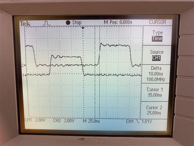
I observed a 10 ns variation (1 TBCLK). I also observe that the EPwm1B signal is stable, but not the EPw1A signal when the trigger is on the Epwm1B's chanel. But not on the EPw1A's chanel, both of them are unstable.
I don't know how to stabilize the signal.
Thank you in advance for your help.
Here are photos of the signal and the difference in variation (Chanel 1 : Epwm1B and chanel 2 : Epwm1A), the pictures represent a PWM signal with 206ns period, dutycycle 50% and deadband of 30% of the demi periode (30.9ns) :
Continuous signal acquisition :
Single acquisition :

Here is my complete code if it helps:
#include "F28x_Project.h"
#include "F2837xD_device.h"
#include "F2837xD_Examples.h"
#include "F2837xD_EPwm_defines.h" // init defines
#include "SFO_V8.h"
#include "board.h"
#include <stdio.h>
float PeriodeNANOsec = 206; //Periode souhaité en NANOSECONDE
float dutycycle = 0.5;
float dutyDB = 0.30; //DN(ns)= dutyDB * Periode/2
//-------------- DEFINITION --------------//
#define LAST_EPWM_INDEX 4
//---------------- VARIABLE ----------------//
uint16_t PRD1_HR;
uint16_t FED;
uint16_t FEDHR;
uint16_t PRD;
uint16_t CMP;
uint16_t CMPHR;
//-------------- GLOBAL ------------------------//
int MEP_ScaleFactor;
volatile struct EPWM_REGS *ePWM[] = {0, &EPwm1Regs, &EPwm2Regs, &EPwm3Regs};
uint16_t status;
float DBns;
//---- APPEL DE FONCTION----//
void PRD_CMP_DB_calculation(float32_t periode, float32_t duty,float32_t dutyDB); //calculation of PRD, CMP and DB values (high resolution)
void initGPIO(void); //GPIO initialization
void initPWM(void); //PWM initialization
//****************** CODE PRINCIPAL***********************//
int main()
{
PRD_CMP_DB_calculation(PeriodeNANOsec,dutycycle,dutyDB);
DBns = dutyDB * PeriodeNANOsec/2;
// Initialize System Control for Control and Analog Subsystems
// Enable Peripheral Clocks
EALLOW;
InitSysCtrl();
EDIS;
// EPWM1A and EPWM1B through all PWMS
initGPIO();
DINT;
// Initialize PIE control registers to their default state.
// The default state is all PIE interrupts disabled and flags
// are cleared.
InitPieCtrl();
// Disable CPU interrupts and clear all CPU interrupt flags:
EALLOW;
IER = 0x0000;
IFR = 0x0000;
// Initialize the PIE vector table with pointers to the shell Interrupt
// Service Routines (ISR).
// This will populate the entire table, even if the interrupt
// is not used in this example. This is useful for debug purposes.
// The shell ISR routines are found in F2837xD_DefaultIsr.c.
// This function is found in F2837xD_PieVect.c.
InitPieVectTable();
// Enable global Interrupts and higher priority real-time debug events:
EINT; // Enable Global interrupt INTM
ERTM; // Enable Global realtime interrupt DBGM
// Calling SFO() updates the HRMSTEP register with calibrated MEP_ScaleFactor.
// HRMSTEP must be populated with a scale factor value prior to enabling
// high resolution period control.
while(status == SFO_INCOMPLETE)
{
status = SFO(); // SFO function returns 2 if an error occurs & # of MEP
if(status == SFO_ERROR) // steps/coarse step exceeds maximum of 255.
{
ESTOP0;
}
}
SysCtl_disablePeripheral(SYSCTL_PERIPH_CLK_TBCLKSYNC);
initPWM();
SysCtl_enablePeripheral(SYSCTL_PERIPH_CLK_TBCLKSYNC);
uint32_t i;
while(1)
{
for(i=1; i<LAST_EPWM_INDEX; i++)
{
(*ePWM[i]).TBPRDHR= PRD1_HR<<8;
}
status = SFO(); // in background, MEP calibration module
// continuously updates MEP_ScaleFactor
if(status == SFO_ERROR)
{
ESTOP0; // SFO function returns 2 if an error occurs & # of
} // MEP steps/coarse step exceeds maximum of 255.
}
}
//------------------ INITIALISATION HRPWM -------------//
void initPWM()
{
uint16_t j;
EALLOW;
CpuSysRegs.PCLKCR0.bit.TBCLKSYNC = 0; // Disable TBCLK within the EPWM
EDIS;
for(j=1; j<LAST_EPWM_INDEX; j++)
{
//------------------ TIME BASE/ CMP --------------------//
(*ePWM[j]).TBCTL.bit.PRDLD = TB_SHADOW; // set Shadow load
(*ePWM[j]).TBPRD= PRD; // PWM frequency = 1/(2*TBPRD))
(*ePWM[j]).CMPA.all = (long) CMP << 16 | CMPHR << 8; //Enable HRPWM duty
(*ePWM[j]).CMPB.all = (long) CMP << 16 | CMPHR << 8;
(*ePWM[j]).TBPHS.all = 0;
(*ePWM[j]).TBCTR = 0;
(*ePWM[j]).TBCTL.bit.CTRMODE = TB_COUNT_UP; // Select up-down count mode
(*ePWM[j]).TBCTL.bit.SYNCOSEL = TB_SYNC_DISABLE;
(*ePWM[j]).TBCTL.bit.HSPCLKDIV = TB_DIV1;
(*ePWM[j]).TBCTL.bit.CLKDIV = TB_DIV1; // TBCLK = SYSCLKOUT
(*ePWM[j]).TBCTL.bit.FREE_SOFT = 3;
//-------------------- SHADOWS -------------------------//
(*ePWM[j]).CMPCTL.bit.LOADAMODE = CC_CTR_PRD; // LOAD CMPA on CTR = PRD
(*ePWM[j]).CMPCTL.bit.LOADBMODE = CC_CTR_PRD;
(*ePWM[j]).CMPCTL.bit.SHDWAMODE = CC_SHADOW;
(*ePWM[j]).CMPCTL.bit.SHDWBMODE = CC_SHADOW;
//------------------ ACTION QUALIFIER -------------------//
(*ePWM[j]).AQCTLA.bit.CAU = AQ_CLEAR; // PWM toggle high/low
(*ePWM[j]).AQCTLA.bit.PRD = AQ_SET; //DO NOT SET TO ZRO, HR period is not stable
//(*ePWM[j]).AQCTLB.bit.CBU = AQ_SET; // PWM toggle high/low
//(*ePWM[j]).AQCTLB.bit.PRD = AQ_CLEAR;
//--------------------- HRPWM --------------------------//
EALLOW;
(*ePWM[j]).HRCNFG.all = 0x0;
(*ePWM[j]).HRCNFG.bit.EDGMODE = HR_BEP; // BOht Edge for the HR period to work
(*ePWM[j]).HRCNFG.bit.CTLMODE = HR_CMP; // CMPAHR and TBPRDHR HR control.
(*ePWM[j]).HRCNFG.bit.HRLOAD = HR_CTR_ZERO_PRD; // load on CTR = 0 and CTR = TBPRD
(*ePWM[j]).HRCNFG.bit.EDGMODEB = HR_BEP; // BOht Edge for the HR period to work
(*ePWM[j]).HRCNFG.bit.CTLMODEB = HR_CMP; // CMPBHR and TBPRDHR HR control
(*ePWM[j]).HRCNFG.bit.HRLOADB = HR_CTR_ZERO_PRD; // load on CTR = 0 and CTR = TBPRD
(*ePWM[j]).HRCNFG.bit.SWAPAB = 0; // ePWMxA and ePWMxB outputs are unchanged
(*ePWM[j]).HRCNFG.bit.AUTOCONV = 1; // Enable autoconversion for HR period
(*ePWM[j]).HRPCTL.bit.TBPHSHRLOADE = 0; // Enable TBPHSHR sync (required for updwn count HR control)
(*ePWM[j]).HRPCTL.bit.HRPE = 1; // Turn on high-resolution period control.
CpuSysRegs.PCLKCR0.bit.TBCLKSYNC = 1; // Enable TBCLK within the EPWM
(*ePWM[j]).TBCTL.bit.SWFSYNC = 1; // Synchronize high resolution phase to start HR period
//-------------------- DEAD BAND -----------------------//
(*ePWM[j]).DBCTL.bit.IN_MODE = DBA_ALL; //ICI EPWMxA est la source des retards de front descendant et de front montant.
(*ePWM[j]).DBCTL.bit.OUT_MODE= DB_FULL_ENABLE ; // See table 15-8
(*ePWM[j]).DBCTL.bit.POLSEL= DB_ACTV_HIC; //Active High Complementary -> tableau 15-8
(*ePWM[j]).DBCTL.bit.HALFCYCLE= 1; //this bit must be set 1 for HR deadband (clock 5ns for DB)
(*ePWM[j]).DBCTL.bit.OUTSWAP = 0;
(*ePWM[j]).DBCTL.bit.SHDWDBREDMODE = 1;
(*ePWM[j]).DBCTL.bit.SHDWDBFEDMODE = 1;
(*ePWM[j]).DBCTL.bit.LOADREDMODE = 2;
(*ePWM[j]).DBCTL.bit.LOADFEDMODE = 2;
(*ePWM[j]).DBRED.all = FED; //Unpacking the assembly
(*ePWM[j]).DBFED.all = FED;
(*ePWM[j]).HRCNFG2.bit.EDGMODEDB= HR_BEP; // DBREDHR and DBFEDHR
(*ePWM[j]).HRCNFG2.bit.CTLMODEDBFED =2; // Load on ZRO
(*ePWM[j]).HRCNFG2.bit.CTLMODEDBRED =2;
(*ePWM[j]).DBREDHR.bit.DBREDHR = FEDHR; //Unpacking the ascent of the two PW1Ms
(*ePWM[j]).DBFEDHR.bit.DBFEDHR = FEDHR; //Unpacking the descent of the two PW1Ms
EDIS;
}
}
//------------------ INITIALISATION GPIO --------------//
void initGPIO()
{
EALLOW; // Enable access to GPIO configuration registers
// CONFIGURE GPIO 0 FOR PWM1A
GpioCtrlRegs.GPAPUD.bit.GPIO0 = 0; // Activate pull-up resistor on pin
GpioCtrlRegs.GPAMUX1.bit.GPIO0 = 1; // Configure pin for PWM1A function
// CONFIGURE GPIO 1 FOR PWM1B
GpioCtrlRegs.GPAPUD.bit.GPIO1 = 0; // Activate pull-up resistor on pin
GpioCtrlRegs.GPAMUX1.bit.GPIO1 = 1; // Configure pin for PWM1B function
EDIS; // Disable access to GPIO configuration registers
}
void PRD_CMP_DB_calculation(float32_t periode, float32_t duty,float32_t dutyDB)
{
//--------- Period and PRDHR calculation ----------//
float invTBCLK= 0.10; //1/TBCLK = 0.1 nanosec, Number of clock strokes with TBCLK=10ns
float PRDfrac=periode*invTBCLK; //Flaot number of TBCLK for the p
int PRDint=(PRDfrac); //the integer part of the split period
PRD=PRDint-1;
PRD1_HR=(PRDfrac-PRDint)*256;
//---------- CMP and CMPHR calculation ------------//
int reste = PRD/2; //Euclidean division to find out how to calculate CMP at 50%duty
if (reste !=0) //If PRd is Odd
{
CMP=PRDint/2 - 1;
}
else //If PRD is even
{
CMP=PRD/2;
}
float frac = PRDfrac*duty; //calculation of CMPHR = frac(PRDfrc*duty)
int ent = (frac);
float CMPHRfrac = frac-ent;
CMPHRfrac = CMPHRfrac*256;
CMPHR=(CMPHRfrac);
//---------- Dead Band and DBHR calculation --------//
float RequiredDBvalue=duty*periode*dutyDB;
float fracFED=RequiredDBvalue*0.2; //*0.2 is equivalent to dividing by 10ns/2 or half a clock cycle
FED=(fracFED);
float fracFEDHR= (fracFED-FED)*128; //DBFED is on 7 bits so for the cacul we realize the (fractionalpart*128)
FEDHR=(fracFEDHR);
}


