Other Parts Discussed in Thread: SYSCONFIG, C2000WARE, TIDM-02010, SFRA, DAC128S085
Dear Sir,
Please find the attched copy of Full code & check Error..
ODU_TI_Project_ADC_03012024.zip
Please check & resolved.

This thread has been locked.
If you have a related question, please click the "Ask a related question" button in the top right corner. The newly created question will be automatically linked to this question.
Dear Sir,
Please find the attched copy of Full code & check Error..
ODU_TI_Project_ADC_03012024.zip
Please check & resolved.

Babaji,
Can you at least provide some background on the issue or error that you are facing? Zipping the project and sending it in the forum with no information whatsoever is not an efficient way to communicate and resolve your issue.
Thanks,
Joseph
Dear Joseph,
Thank for your prompt reply.
We are Developing New firmware for Air Conditioner Out Door Unit(ODU).
in that i am using TI MCU TMS320F2800137.
now we interfacing with different ADC
1.ADCC : using for temperature sensor like ENVI Temp , EVAP Temp & PIPE Temp : These are working good in that No error/issue.
2. Now we are Read Input AC voltage/Current & VDC voltage by using ADCA c2000.syscfg .
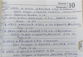
Here following ADCA used
VAC:SOC1 / A10 : ADCIN10 is converted
IAC1: SOC0 / A9 : ADCIN9 is converted
VDC : SCO2 / A4 : ADCIN4 is converted
Here we are facing some error/issue while building project for your reference please find below attachment & above full code.
So Please import this project at your end defiantly this will help for your further details information as you required.
Kindly request you to import project.
Babaji,
You created interrupt handlers in SysConfig namely pfcCtrlISR, motor1CtrlISR and motor2CtrlISR under INTERRUPT but you did not create the interrupt functions. This is what caused the errors. You need to manually create the ISRs and include them in your main.c code.
I added below template that you can start with. The interrupt numbers and groups for acknowledgement was taken from what you have defined in SysConfig under board.h. You need to check for accuracy though.
__interrupt void pfcCtrlISR(void)
{
    // Place ISR code here....


    ADC_clearInterruptStatus(myADCA_BASE, ADC_INT_NUMBER2);
    if(true==ADC_getInterruptOverflowStatus(myADCA_BASE, ADC_INT_NUMBER2))
    {
        ADC_clearInterruptOverflowStatus(myADCA_BASE, ADC_INT_NUMBER2);
        ADC_clearInterruptStatus(myADCA_BASE, ADC_INT_NUMBER2);
    }
    Interrupt_clearACKGroup(INT_PFC_MTRS_2_INTERRUPT_ACK_GROUP);
 }

__interrupt void motor1CtrlISR(void)
{
    // Place ISR code here....


    ADC_clearInterruptStatus(myADCA_BASE, ADC_INT_NUMBER3);
    if(true==ADC_getInterruptOverflowStatus(myADCA_BASE, ADC_INT_NUMBER3))
    {
        ADC_clearInterruptOverflowStatus(myADCA_BASE, ADC_INT_NUMBER3);
        ADC_clearInterruptStatus(myADCA_BASE, ADC_INT_NUMBER3);
    }
    Interrupt_clearACKGroup(INT_PFC_MTRS_3_INTERRUPT_ACK_GROUP);
 }

__interrupt void motor2CtrlISR(void)
{
    // Place ISR code here....


    ADC_clearInterruptStatus(myADCA_BASE, ADC_INT_NUMBER4);
    if(true==ADC_getInterruptOverflowStatus(myADCA_BASE, ADC_INT_NUMBER4))
    {
        ADC_clearInterruptOverflowStatus(myADCA_BASE, ADC_INT_NUMBER4);
        ADC_clearInterruptStatus(myADCA_BASE, ADC_INT_NUMBER4);
    }
    Interrupt_clearACKGroup(INT_PFC_MTRS_4_INTERRUPT_ACK_GROUP);
 }
Regards,
Joseph
Thank you Joseph error resolved.
But i have some problem for reading ADC value.
means i have used ADCc for temperature sensor reading & ADCA used for PFC DC :A4/C14 ADCA,PFC_VAC:A10,PFC_IAC:A9.
But i have merge or used both ADC at a time then ADCA count can not read value/display.
In register ADCc count value can display correctly but ADCA value can not display anything means zero.
for your reference please check main.c code
//#############################################################################
//
// FILE:   empty_driverlib_main.c
//
//! \addtogroup driver_example_list
//! <h1>Empty Project Example</h1>
//!
//! This example is an empty project setup for Driverlib development.
//!
//
//#############################################################################
//
//
// $Copyright:
// Copyright (C) 2023 Texas Instruments Incorporated - http://www.ti.com/
//
// Redistribution and use in source and binary forms, with or without
// modification, are permitted provided that the following conditions
// are met:
//
//   Redistributions of source code must retain the above copyright
//   notice, this list of conditions and the following disclaimer.
//
//   Redistributions in binary form must reproduce the above copyright
//   notice, this list of conditions and the following disclaimer in the
//   documentation and/or other materials provided with the
//   distribution.
//
//   Neither the name of Texas Instruments Incorporated nor the names of
//   its contributors may be used to endorse or promote products derived
//   from this software without specific prior written permission.
//
// THIS SOFTWARE IS PROVIDED BY THE COPYRIGHT HOLDERS AND CONTRIBUTORS
// "AS IS" AND ANY EXPRESS OR IMPLIED WARRANTIES, INCLUDING, BUT NOT
// LIMITED TO, THE IMPLIED WARRANTIES OF MERCHANTABILITY AND FITNESS FOR
// A PARTICULAR PURPOSE ARE DISCLAIMED. IN NO EVENT SHALL THE COPYRIGHT
// OWNER OR CONTRIBUTORS BE LIABLE FOR ANY DIRECT, INDIRECT, INCIDENTAL,
// SPECIAL, EXEMPLARY, OR CONSEQUENTIAL DAMAGES (INCLUDING, BUT NOT
// LIMITED TO, PROCUREMENT OF SUBSTITUTE GOODS OR SERVICES; LOSS OF USE,
// DATA, OR PROFITS; OR BUSINESS INTERRUPTION) HOWEVER CAUSED AND ON ANY
// THEORY OF LIABILITY, WHETHER IN CONTRACT, STRICT LIABILITY, OR TORT
// (INCLUDING NEGLIGENCE OR OTHERWISE) ARISING IN ANY WAY OUT OF THE USE
// OF THIS SOFTWARE, EVEN IF ADVISED OF THE POSSIBILITY OF SUCH DAMAGE.
// $
//#############################################################################

//
// Included Files
//
#include "math.h"
#include "driverlib.h"
#include "device.h"
#include "board.h"
#include "c2000ware_libraries.h"

#include "adc.h"

//
// Main
//
//int16_t ADC_getTemperatureC(uint16_t tempResult, ADC_ReferenceMode refMode,float32_t vref);

float32_t tempResult,refMode,vref,Temp_Sensor_Ambient,Temp_Sensor1,value,Temp_Sensor_coils,Temp_Sensor_Pipes;
float32_t VacSen,resultBase,ppbNumber,ADCRESULT0;
//----------Positive Temp-----------
#define BASEREADINGPOSITIVE 960     //;    //980//800
#define SPANCOUNTPOSITIVE 2744     //2020//1900
#define MAXTEMPPOSITIVE 85
//-----------Negative Temp-------
#define BASEREADINGNEGATIVE 54    //980//800
#define SPANCOUNTNEGATIVE 444     //2020//1900
#define MAXTEMPNEGATIVE 40

#define BASEREADINGCOILS 1520    //980//800
#define SPANCOUNTCOILS 1930     //2020//1900
#define MAXTEMPCOILS 50

//-----------------ADD_02012024---------
#define ADC_RESOLUTION_VALUE                (4096U)
#define LOG_10_E                            (0.434294f)
#define TEMP_T_25_K                         (298.15f)//kevin
//air temperature
#define TEMP_AIR_RES_T_25                   (10000U)//Ohm
#define TEMP_AIR_BETA                       (3950U)
#define TEMP_AIR_RES_GND                    (10000U)//Ohm

//coil temperature
#define TEMP_COIL_RES_T_25                  (10000U)//Ohm
#define TEMP_COIL_BETA                      (3950U)
#define TEMP_COIL_RES_GND                   (10000U)//Ohm


unsigned int uiRowTemp;
//static uint32_t uiSubValue;
unsigned long uiTemp;
float fTempValue;
unsigned int tempnewvalue1;
unsigned int tempnewvalue2;
unsigned int tempnewvalue3;


void initEPWM(void);//new
static float ntc_sensor_get_temp(float res, uint16_t res_25, uint16_t beta);

void main(void)
{
    uint32_t* read_ADC_Value=(uint32_t*)0x00000B40;
    uint32_t* read_ADC_Value2=(uint32_t*)0x00000B41;
    uint32_t* read_ADC_Value3=(uint32_t*)0x00000B42;
    //
    // Initialize device clock and peripherals
    //
    Device_init();

    //
    // Disable pin locks and enable internal pull-ups.
    //
    Device_initGPIO();

    //
    // Initialize PIE and clear PIE registers. Disables CPU interrupts.
    //
    Interrupt_initModule();

    //
    // Initialize the PIE vector table with pointers to the shell Interrupt
    // Service Routines (ISR).
    //
    Interrupt_initVectorTable();

    //
    // PinMux and Peripheral Initialization
    //
    Board_init();

    initEPWM();//new

    //
    // C2000Ware Library initialization
    //
    C2000Ware_libraries_init();

    //
    // Enable Global Interrupt (INTM) and real time interrupt (DBGM)
    //
    EINT;
    ERTM;
    EPWM_enableADCTrigger(EPWM1_BASE, EPWM_SOC_A);//new
    EPWM_setTimeBaseCounterMode(EPWM1_BASE, EPWM_COUNTER_MODE_UP);//new

    while(1)
    {
        tempnewvalue1 = (*read_ADC_Value);
        tempnewvalue2 = (*read_ADC_Value2);
        tempnewvalue3 = (*read_ADC_Value3);
//--------------------------------------Ambient sensor-------------------------------------------------
        fTempValue = (float)(ADC_RESOLUTION_VALUE - tempnewvalue1);
        fTempValue *= (TEMP_AIR_RES_GND / tempnewvalue1);
        Temp_Sensor_Ambient = (float)ntc_sensor_get_temp(fTempValue, TEMP_AIR_RES_T_25, TEMP_AIR_BETA);
//-------------------------------------coil sensor------------------------------------------------------
        fTempValue = (float)(ADC_RESOLUTION_VALUE - tempnewvalue2);
        fTempValue *= (TEMP_COIL_RES_GND / tempnewvalue2);
        Temp_Sensor_coils = (float)ntc_sensor_get_temp(fTempValue, TEMP_COIL_RES_T_25, TEMP_COIL_BETA);
//-------------------------------------Pipe sensor------------------------------------------------------
        fTempValue = (float)(ADC_RESOLUTION_VALUE - tempnewvalue3);
        fTempValue *= (TEMP_COIL_RES_GND / tempnewvalue3);
        Temp_Sensor_Pipes = (float)ntc_sensor_get_temp(fTempValue, TEMP_COIL_RES_T_25, TEMP_COIL_BETA);
        //else((tempnewvalue2 < 15) || (tempnewvalue2 >= 3600))
    }
}

static float ntc_sensor_get_temp(float res, uint16_t res_25, uint16_t beta)
{
    float temp = 1 / (1 / TEMP_T_25_K + (log10((float)res/res_25) / LOG_10_E / beta));
    temp -= 273.15;
    return temp;
}
//
__interrupt void INT_myADCA_1_ISR(void)
{
    ADC_clearInterruptStatus(myADCA_BASE, ADC_INT_NUMBER1);
    if(true==ADC_getInterruptOverflowStatus(myADCA_BASE, ADC_INT_NUMBER1))
    {
        ADC_clearInterruptOverflowStatus(myADCA_BASE, ADC_INT_NUMBER1);
        ADC_clearInterruptStatus(myADCA_BASE, ADC_INT_NUMBER1);
    }
    Interrupt_clearACKGroup(INT_myADCA_1_INTERRUPT_ACK_GROUP);
 }
// End of File

__interrupt void pfcCtrlISR(void)
{
    // Place ISR code here....


    ADC_clearInterruptStatus(PFC_MTRS_BASE, ADC_INT_NUMBER2);
    if(true==ADC_getInterruptOverflowStatus(PFC_MTRS_BASE, ADC_INT_NUMBER2))
    {
        ADC_clearInterruptOverflowStatus(PFC_MTRS_BASE, ADC_INT_NUMBER2);
        ADC_clearInterruptStatus(PFC_MTRS_BASE, ADC_INT_NUMBER2);
    }
    Interrupt_clearACKGroup(INT_PFC_MTRS_2_INTERRUPT_ACK_GROUP);
 }

__interrupt void motor1CtrlISR(void)
{
    // Place ISR code here....


    ADC_clearInterruptStatus(PFC_MTRS_BASE, ADC_INT_NUMBER3);
    if(true==ADC_getInterruptOverflowStatus(PFC_MTRS_BASE, ADC_INT_NUMBER3))
    {
        ADC_clearInterruptOverflowStatus(PFC_MTRS_BASE, ADC_INT_NUMBER3);
        ADC_clearInterruptStatus(PFC_MTRS_BASE, ADC_INT_NUMBER3);
    }
    Interrupt_clearACKGroup(INT_PFC_MTRS_3_INTERRUPT_ACK_GROUP);
 }

__interrupt void motor2CtrlISR(void)
{
    // Place ISR code here....


    ADC_clearInterruptStatus(PFC_MTRS_BASE, ADC_INT_NUMBER4);
    if(true==ADC_getInterruptOverflowStatus(PFC_MTRS_BASE, ADC_INT_NUMBER4))
    {
        ADC_clearInterruptOverflowStatus(PFC_MTRS_BASE, ADC_INT_NUMBER4);
        ADC_clearInterruptStatus(PFC_MTRS_BASE, ADC_INT_NUMBER4);
    }
    Interrupt_clearACKGroup(INT_PFC_MTRS_4_INTERRUPT_ACK_GROUP);
 }
//
//
// initEPWM - Function to configure ePWM1 to generate the SOC.
//
void initEPWM(void)
{
    //
    // Disable SOCA
    //
    EPWM_disableADCTrigger(EPWM1_BASE, EPWM_SOC_A);

    //
    // Configure the SOC to occur on the first up-count event
    //
    EPWM_setADCTriggerSource(EPWM1_BASE, EPWM_SOC_A, EPWM_SOC_TBCTR_U_CMPA);
    EPWM_setADCTriggerEventPrescale(EPWM1_BASE, EPWM_SOC_A, 1);

    //
    // Set the compare A value to 1000 and the period to 1999
    // Assuming ePWM clock is 100MHz, this would give 50kHz sampling
    // 50MHz ePWM clock would give 25kHz sampling, etc.
    // The sample rate can also be modulated by changing the ePWM period
    // directly (ensure that the compare A value is less than the period).
    //
    EPWM_setCounterCompareValue(EPWM1_BASE, EPWM_COUNTER_COMPARE_A, 1000);
    EPWM_setTimeBasePeriod(EPWM1_BASE, 1999);

    //
    // Set the local ePWM module clock divider to /1
    //
    EPWM_setClockPrescaler(EPWM1_BASE,
                           EPWM_CLOCK_DIVIDER_1,
                           EPWM_HSCLOCK_DIVIDER_1);

    //
    // Freeze the counter
    //
    EPWM_setTimeBaseCounterMode(EPWM1_BASE, EPWM_COUNTER_MODE_STOP_FREEZE);
}
Babaji,
It could be possible that ADCA has not been configured correctly. Can you inspect the ADCA registers in CCS register view to confirm that the registers have the correct values assigned for SOC (channel, ACQPS, trigger..etc) and if ADCA is powered up?
Regards,
Joseph
It could be possible that ADCA has not been configured correctly. Can you inspect the ADCA registers in CCS register view to confirm that the registers have the correct values assigned for SOC (channel, ACQPS, trigger..etc) and if ADCA is powered up?
here i will select single ADC like ADCA (NOT ADCC) ,PFC_VDC:A4 then it will work properly .
But i configure both ADC & then check ADCA AdcaResultRegs (ADCRESULT0-ADCRESULT15) should be zero no value updated.
If ADCA used single i.e.not ADCC then work correctly means no configured issue.
Also for your better understanding please find the below attachment.
ODU_TI_Project_ADC_08012024.zip
Main issue is while using both ADC means ADCA & ADCC.
Please check & resolved issue as early as possible.
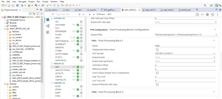
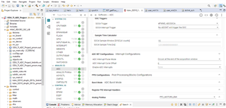
Babaji,
Unfortunately at this time I am not able to import your project as there are dependencies that are not in my set up. Can you show the ADC initialization setup for the ADCC (temperature sensor) and ADCA (VAC, SOC1; IAC1, SOC0 and VDC, SOC2). I would also like to see the trigger set up (EPWM if this is what is used for ADC triggers). Alternatively, you can also display ADCA and ADCC register contents as this would show how ADC was configured.
Regards,
Joseph
Dear Joseph,
Thanks for your more valuable reply.
Can you show the ADC initialization setup for the ADCC (temperature sensor) and ADCA (VAC, SOC1; IAC1, SOC0 and VDC, SOC2). I would also like to see the trigger set up (EPWM if this is what is used for ADC triggers). Alternatively, you can also display ADCA and ADCC register contents as this would show how ADC was configured.
for above details please check attachment
 .
.
Unfortunately at this time I am not able to import your project as there are dependencies that are not in my set up.
Please try this one by today please for your better understanding if any point is missing from my sideODU_TI_Project_ADC_09012024.zip.
Babaji,
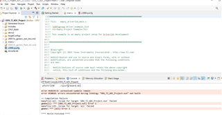
I'm getting errors importing your project. I noted a couple of concerns based on the snippet you sent. I cannot debug your issues but below are pointers that will help you:
- Your code seems to be branching to an error handler. You need to step through your code to see where this is happening. You can do this by restarting your code an instead of hitting the play button, use the code step functions highlited below:

You need to note the statement(s) that gets executed before the code branches to the error handler and fix this first.
- In the SOC setup,I can see that you have used EPWM7 SOCA and B to trigger conversions, however, i do not see you initialize or set up EPWM7 in your initEPWM() function on main.c. Only EPWM1 is initialized.
- In your SOC set up, you have configured them to trigger ADC interrupts but your ADC ISRs are not doing anything. Any action that needs to be performed after the ADC is converted needs to be placed in the ISR routines.
Regards,
Joseph
Dear Joseph,
- In the SOC setup,I can see that you have used EPWM7 SOCA and B to trigger conversions, however, i do not see you initialize or set up EPWM7 in your initEPWM() function on main.c. Only EPWM1 is initialized.
Thanks for your big support.
Issue is resolved because i used ePWM7 in SOCA but in main.c i only initialized only ePWM1.
Once again thank you.
i will check next part.
Dear Joseph,
Please find the attached copy of full code try to import please.
ADCC can read correct value of sensor but ADCA can not display value please see attached video.
Babaji,
Sorry, we do not debug customer application codes. If you need further assistance, please contact your field application team. So far the past issues in your code, like missing ISRs, uninitialized modules...etc..are covered in the examples in C2000Ware. You can first try the examples to check the correct way of triggering a conversion using EPWM and processing them through ADC ISRs and use the same concept in your application code.
Regards,
Joseph
Dear joseph,
For AC input Voltage & AC input current i used below ADCA.
for AC input Voltage i used ADCA : A10
for AC input current i used ADCA : A9
For Both ADCA the required ADCA count occur correctly.
please suggest formula for convert ADCA count into AC input voltage & current like 230VAC.
For Input voltage range is 165VAC to 265VAC.
for reference voltage is 3.3V ,12 bit ADC used.
Hi Babaji,
Please refer to TI reference design (TIDM-02010) that you can start with. Review the schematic diagrams to see how the 230VAC mains is sampled to interface to the F2800137x ADC input.
Best regards,
Joseph
Dear Joseph,
Please refer to TI reference design (TIDM-02010) that you can start with. Review the schematic diagrams to see how the 230VAC mains
Please can you send sample code.
How to convert adc count to 230vac .
Please tell which formula can i used.
Babaji,
I suggest that you go follow the links in TIDM-02010. Download the design guide in the link. Look at the overall block diagram in Figure 2-1 to have a general idea on how AC voltage and current is sampled. Section 2.4.1.3 shows the schematic for AC interface through the differential buffer U5B. Section 2.4.1.5 shows the schematics for current sensing. Follow the formulas in this design guide on current sensing. Section 3.2 describes where to get the firmware.
It is probably better for you to start with this design as this package provides you all that you need (HW and SW) rather than starting from scratch and avoid back and forth questions that are already addressed by this reference design which is similar to the application that you are working on.
Regards,
Joseph
Section 3.2 describes where to get the firmware.
Dear Joseph,
here i check firmware as per attached code
__interrupt void pfcCtrlISR(void)
{
    pfcVars.ISRCount++;

    // acknowledge the interrupt of PFC
    HAL_ackPFCADCInt();

    // Interleaved PFC using DMA for Iac, 4 times average
    // read the ADC data with offsets
    HAL_readPFCADCData(&adcDataPFC);        // ILPFC

#if defined(ILPFC_DCH_EN)
    // convert acbus current
     if(pfcVars.flagEnableILMode == true)
     {
         adcDataPFC.IacBus = adcDataPFC.currentAC_sf *
                 ((float32_t)(ADC_readPPBResult(PFC_IAC_ADCRES_BASE, PFC_IAC1_ADC_PPB_NUM) +
                 ADC_readPPBResult(PFC_IAC_ADCRES_BASE, PFC_IAC2_ADC_PPB_NUM)));
     }
     else
     {
#if defined(SPPFC_CHA_EN)
         adcDataPFC.IacBus = adcDataPFC.currentAC_sf * 2.0f *
                 ((float32_t)(ADC_readPPBResult(PFC_IAC_ADCRES_BASE, PFC_IAC1_ADC_PPB_NUM)));
#elif defined(SPPFC_CHB_EN)
         adcDataPFC.IacBus = adcDataPFC.currentAC_sf * 2.0f *
                 ((float32_t)(ADC_readPPBResult(PFC_IAC_ADCRES_BASE, PFC_IAC2_ADC_PPB_NUM)));
#endif      // SPPFC_CHA_EN || SPPFC_CHB_EN
     }
#elif defined(SPPFC_CHA_EN)
     // convert acbus current
      adcDataPFC.IacBus = adcDataPFC.currentAC_sf * 2.0f *
              ((float32_t)(ADC_readPPBResult(PFC_IAC_ADCRES_BASE, PFC_IAC1_ADC_PPB_NUM)));
#elif defined(SPPFC_CHB_EN)
      // convert acbus current
       adcDataPFC.IacBus = adcDataPFC.currentAC_sf * 2.0f *
               ((float32_t)(ADC_readPPBResult(PFC_IAC_ADCRES_BASE, PFC_IAC2_ADC_PPB_NUM)));
#else      // !(SPPFC_CHA_EN || SPPFC_CHB_EN)
#error Not select a right PFC output mode
#endif      // !(SPPFC_CHA_EN || SPPFC_CHB_EN)

    adcDataPFC.IacBus = (adcDataPFC.IacBus < USER_PFC_ADC_PU_SF) ?
            USER_PFC_ADC_PU_SF : adcDataPFC.IacBus; // minimum positive current

    // calculate AC bus voltage
#if defined(HVMTRPFC_REV1P1) || defined(DMCPFC_REV0P1)
    adcDataPFC.ValBus = adcDataPFC.ValBus - adcDataPFC.offset_Vac;
    adcDataPFC.VanBus = adcDataPFC.VanBus - adcDataPFC.offset_Van;

    if(adcDataPFC.ValBus > adcDataPFC.VanBus)
    {
        adcDataPFC.VacBus = adcDataPFC.ValBus - adcDataPFC.VanBus;
    }
    else
    {
        adcDataPFC.VacBus = adcDataPFC.VanBus - adcDataPFC.ValBus;
    }
#else
    adcDataPFC.VacBus = fabsf(adcDataPFC.VacSen);
#endif  // !(HVMTRPFC_REV1P1 | DMCPFC_REV0P1)

#if defined(SFRA_ENABLE) && (SFRA_TEST_TYPE == SFRA_TEST_PFC)
    sfraNoiseInj_pu = 0.0f;
    sfraNoiseVpfc = 0.0f;
    sfraNoiseIpfc = 0.0f;

    sfraNoiseInj_pu = SFRA_F32_inject(0.0f);

    if(sfraTestLoop == SFRA_TEST_PFC_VOLTAGE)
    {
        sfraNoiseVpfc = sfraNoiseInj_pu;
    }
    else if(sfraTestLoop == SFRA_TEST_PFC_CURRENT)
    {
        sfraNoiseIpfc = sfraNoiseInj_pu;
    }
#endif  // (SFRA_ENABLE && SFRA_TEST_PFC)

    pfcVars.counterVoltage++;

    switch(pfcVars.counterVoltage)
    {
        case USER_PFC_NUM_ISR_TICKS_PER_VOLTAGE_TICK:       // 36kHz/5=7.2kHz
            // voltage loop
            if(pfcVars.flagEnableVoltageLoop == true)
            {
#if defined(SFRA_ENABLE) && (SFRA_TEST_TYPE == SFRA_TEST_PFC)
                pfcVars.IdcRefOut =
                    DCL_runPI_C4(&gv, pfcVars.VdcTrajInt + sfraNoiseVpfc, pfcVars.VdcBusLPF);
#else   // !(SFRA_ENABLE) && (SFRA_TEST_TYPE == SFRA_TEST_PFC)
                pfcVars.IdcRefOut =
                       DCL_runPI_C4(&gv, pfcVars.VdcTrajInt, pfcVars.VdcBus_pu);
#endif  // !(SFRA_ENABLE) && (SFRA_TEST_TYPE == SFRA_TEST_PFC)

            }
            else    // pfcVars.flagEnableVoltageLoop == false
            {
                gv.i6 = 1.0f;
                gv.i10 = gv.i11 = 0.0f;

                pfcVars.IdcRefOut = 0.0;
            }

#if(PFC_BUILDLEVEL == PFC_LEVEL_4)
            pfcVars.IdcRef = pfcVars.IdcRefOut;
#endif
            pfcVars.counterVoltage = 0;

            break;

        case 1: // twice voltage control loop frequency
            // 3.130 = (1.0 / minimum voltage)^2, 48VAC
            pfcVars.VinvSqr = pfcVars.invRmsSqrCoef / (pfcVars.VacRms_pu * pfcVars.VacRms_pu);
            pfcVars.VinvSqr = (pfcVars.VinvSqr > 3.130f) ? 3.130f : pfcVars.VinvSqr;

            break;

        case 2: // twice voltage control loop frequency
            //Calculate RMS input voltage and input frequency, 7.2kHz
            measPower.i = adcDataPFC.IacBus;
            measPower.v = adcDataPFC.VacBus;

            POWER_MEAS_FAST_run(&measPower);

            pfcVars.IacRms_pu = measPower.iRms;
            pfcVars.VacRms_pu = measPower.vRms;

            //Divided by 2 because the signal is rectified
            pfcVars.FreqAc_Hz = measPower.acFreq * 0.5f;

            break;

        case 3:
            pfcVars.VdcBus_V = adcDataPFC.VdcBus * USER_PFC_ADC_FULL_SCALE_DC_VOLTAGE_V;

            // convert dc bus voltage from pu to SI unit
            pfcVars.VdcBusLPF = pfcVars.VdcBusLPF +
                    (adcDataPFC.VdcBus - pfcVars.VdcBusLPF) * pfcVars.lpfVdcCoeff;

            pfcVars.VdcBusLPF_V = pfcVars.VdcBusLPF * USER_PFC_ADC_FULL_SCALE_DC_VOLTAGE_V;

            // run notch filter
#if !defined(NOTCH_FILTER)
            pfcVars.VdcBus_pu = pfcVars.VdcBusLPF;
#else   // NOTCH_FILTER
            FILTER_NOTCH_set_in(filterNotchHandle, pfcVars.VdcBusLPF);
            FILTER_NOTCH_run(filterNotchHandle, filterCoeffHandle);
            pfcVars.VdcBusNotch = FILTER_NOTCH_get_out(filterNotchHandle);
            pfcVars.VdcBus_pu = pfcVars.VdcBusNotch;
#endif   // NOTCH_FILTER

#if (PFC_BUILDLEVEL == PFC_LEVEL_4) && defined(ILPFC_DCH_EN) && defined(ILPFC_SWM_EN)
            // switch PFC mode between interleave and single phase
            if(pfcVars.IdcRef > pfcVars.IdcRefSwILOn)
            {
                if(pfcVars.flagEnableILMode == false)
                {
                    pfcVars.flagEnableILMode = true;
                    gi.x1 = gi.x1 * 0.5f;
                    gi.x2 = gi.x2 * 0.5f;

                    HAL_enablePFCILPWM(halPFCHandle);
                }
            }
            else if(pfcVars.IdcRef < pfcVars.IdcRefSwILOff)
            {
                if(pfcVars.flagEnableILMode == true)
                {
                    pfcVars.flagEnableILMode = false;
                    gi.x1 = gi.x1 * 2.0f;
                    gi.x2 = gi.x2 * 2.0f;

#if defined(SPPFC_CHA_EN)
            HAL_disableILPFCPowerChB(halPFCHandle);
#elif defined(SPPFC_CHB_EN)
            HAL_disableILPFCPowerChA(halPFCHandle);
#else
            HAL_disableILPFCPowerChB(halPFCHandle);
#endif      // SPPFC_CHA_EN || SPPFC_CHB_EN
                }
            }
#endif  // (PFC_BUILDLEVEL == PFC_LEVEL_4) && ILPFC_DCH_EN && ILPFC_SWM_EN_N

            break;

        case 4:
            // ramp control
            if(pfcVars.flagEnablePFC == true)
            {
    #if(PFC_BUILDLEVEL >= PFC_LEVEL_3)
                if(pfcVars.VdcBus_V > USER_PFC_ENABLE_CURRENT_LOOP_V)
                {
                    pfcVars.flagEnableCurrentLoop = true;
                }
                else if(pfcVars.VdcBus_V < USER_PFC_DISABLE_CURRENT_LOOP_V)
                {
                    pfcVars.flagEnableCurrentLoop = false;
                }
    #endif

    #if(PFC_BUILDLEVEL == PFC_LEVEL_4)
                if(pfcVars.VacRms_V >= USER_PFC_ENABLE_VOLTAGE_LOOP_V)
                {
                    pfcVars.flagEnableVoltageLoop = true;
                }
                else if(pfcVars.VacRms_V < USER_PFC_DISABLE_VOLTAGE_LOOP_V)
                {
                    pfcVars.flagEnableVoltageLoop = false;
                }
    #endif

                if(pfcVars.flagFirstVoltageLoop == true)
                {
                    pfcVars.IacRef = adcDataPFC.IacBus;
                    pfcVars.VdcTrajInt = pfcVars.VdcBusLPF;

                    pfcVars.flagFirstVoltageLoop = false;
                }

                float32_t VdcError = pfcVars.VdcTrajTraget - pfcVars.VdcTrajInt;

                if(VdcError > pfcVars.VdcTrajRate)
                {
                    pfcVars.VdcTrajInt = pfcVars.VdcTrajTraget + pfcVars.VdcTrajRate;
                }
                else if(VdcError < -pfcVars.VdcTrajRate)
                {
                    pfcVars.VdcTrajInt = pfcVars.VdcTrajTraget - pfcVars.VdcTrajRate;
                }
                else
                {
                    pfcVars.VdcTrajInt = pfcVars.VdcTrajTraget;
                    pfcVars.flagStatePFC = true;
                }
            }
            else    // pfcVars.flagEnablePFC == false
            {
                pfcVars.IdcRef = 0.0f;

                pfcVars.IacRef = adcDataPFC.IacBus;
                pfcVars.VdcTrajInt = pfcVars.VdcBusLPF;
                pfcVars.dutyOut = 0.0;

                pfcVars.flagEnableCurrentLoop = false;
                pfcVars.flagEnableVoltageLoop = false;
                pfcVars.flagFirstVoltageLoop = true;
                pfcVars.flagStatePFC = false;
            }
            break;

        default:
            break;
    }

    pfcVars.IacRef = pfcVars.VinvSqr * adcDataPFC.VacBus * pfcVars.IdcRef;

    pfcVars.IacRef = (pfcVars.IacRef > pfcVars.IacPeak_pu) ?
            pfcVars.IacPeak_pu : pfcVars.IacRef;

    pfcVars.IacRef = (pfcVars.IacRef < 0.0f) ? 0.0f : pfcVars.IacRef;

    pfcVars.IacSen = adcDataPFC.IacBus;

    // run current loop controller
    if(pfcVars.flagEnableCurrentLoop == true)
    {
#if defined(SFRA_ENABLE) && (SFRA_TEST_TYPE == SFRA_TEST_PFC)

        pfcVars.IacError = (pfcVars.IacRef + sfraNoiseIpfc) - pfcVars.IacSen;

        pfcVars.giOut = DCL_runDF22_C1(&gi, pfcVars.IacError);
#else
        pfcVars.IacError = pfcVars.IacRef - pfcVars.IacSen;

        pfcVars.giOut = DCL_runDF22_C1(&gi, pfcVars.IacError);
#endif  // (SFRA_ENABLE) && (SFRA_TEST_TYPE == SFRA_TEST_PFC)

        pfcVars.dutyOut = (pfcVars.giOut > pfcVars.dutyOutMaxSet) ? pfcVars.dutyOutMaxSet : pfcVars.giOut;
        pfcVars.dutyOut = (pfcVars.giOut < 0.0f) ? 0.0f : pfcVars.giOut;

        gi.x1 = pfcVars.dutyOut;        // store the output for next cycle
    }
    else
    {
        gi.x1 = gi.x2 = 0.0f;

#if(PFC_BUILDLEVEL >= PFC_LEVEL_3)
        pfcVars.dutyOut = 0.0;
#endif
    }

#if(PFC_BUILDLEVEL >= PFC_LEVEL_3)
    // over peak voltage protection
    if(adcDataPFC.VdcBus > pfcVars.VdcBusShutDown)      // 410.0VDC, set a right value according to the system
    {
        pfcVars.faultPFCNow.bit.shutDownVoltage = 1;
        pfcVars.dutyOut = 0.0f;

        gv.i10 = gv.i10 * 0.75f;
        gv.i11 = 0.0f;
    }
#endif

#if defined(SFRA_ENABLE) && (SFRA_TEST_TYPE == SFRA_TEST_PFC)
    // Collect the SFRA data
    if(sfraTestLoop == SFRA_TEST_PFC_CURRENT)
    {
        sfraNoiseOut = pfcVars.dutyOut;
        sfraNoiseFdb = pfcVars.IacSen;
    }
    else if(sfraTestLoop == SFRA_TEST_PFC_VOLTAGE)
    {
        sfraNoiseOut = pfcVars.IdcRefOut;
        sfraNoiseFdb = pfcVars.VdcBusLPF;
    }

    SFRA_COLLECT((float32_t*)&sfraNoiseOut, (float32_t*)&sfraNoiseFdb);
#endif  // (SFRA_ENABLE) && (SFRA_TEST_TYPE == SFRA_TEST_PFC)

#if(PFC_BUILDLEVEL == PFC_LEVEL_1)
    // output 50%
    pwmDataPFC.dutyValue = 0.5f;
#elif(PFC_BUILDLEVEL >= PFC_LEVEL_2)
    // manual set the duty
    pwmDataPFC.dutyValue = pfcVars.dutyOut;
#endif

    // write the PWM compare values
    HAL_writePFCPWMData(halPFCHandle, &pwmDataPFC);


#if defined(DATALOGF2_EN) && defined(DATALOG_PFC)
    DATALOGIF_updateWithDMA(datalogHandle);

    // Force trig DMA channel to save the data
    HAL_trigDMAforDLOG(halHandle, 0);
    HAL_trigDMAforDLOG(halHandle, 1);

#endif  // DATALOGF2_EN

#if defined(DAC128S_ENABLE) && defined(DAC_FASTUPDATE)
#if defined(DAC80504_SEL)
    DAC80504_writeData(dac128sHandle);
#else   // DAC128S805
    DAC128S_writeData(dac128sHandle);
#endif  // DAC128S805
#endif  // DAC128S_ENABLE

#if defined(EPWMDAC_MODE) && defined(PWMDAC_PFC)
    // connect inputs of the PWMDAC module.
    HAL_writePWMDACData(halHandle, &pwmDACData);
#endif  // EPWMDAC_MODE

#ifdef DEBUG_MONITOR_EN
    if(pfcVars.flagClearRecord == 1)
    {
        pfcVars.VdcBusMax_V = 0.0f;
        pfcVars.VdcBusMin_V = 500.0f;
        pfcVars.flagClearRecord = 0;
    }
    else
    {
        if(pfcVars.VdcBus_V > pfcVars.VdcBusMax_V)
        {
            pfcVars.VdcBusMax_V = pfcVars.VdcBus_V;
        }

        if(pfcVars.VdcBus_V < pfcVars.VdcBusMin_V)
        {
            pfcVars.VdcBusMin_V = pfcVars.VdcBus_V;
        }
    }
#endif  // DEBUG_MONITOR_EN

    return;
} // end of mainISR() function
below code i can not understand.
so please suggest.
static inline void POWER_MEAS_FAST_run(POWER_MEAS_FAST *v)
{
    v->currSign = ( v->v > v->threshold) ? 1 : 0;
    v->vSqrSum = v->vSqrSum + (v->v * v->v);
    v->iSqrSum = v->iSqrSum + (v->i * v->i);

    v->nSamples++;
    v->zcd = 0;

    if((v->prevSign != v->currSign) && (v->currSign == 1))
    {
        // check if the nSamples are in the ball park of a real frequency
        // that can be on the grid, this is done by comparing the nSamples
        // with the max value and min value it can be for the
        // AC Grid Connection these Max and Min are initialized by the
        // user in the code
        if(v->nSamplesMin < v->nSamples )
        {
            float32_t inverse_nSamples = (1.0f) / ((float32_t)v->nSamples);
            float32_t sqrt_inverse_nSamples = sqrtf(inverse_nSamples);

            v->vRms = sqrtf(v->vSqrSum) * sqrt_inverse_nSamples;
            v->iRms = sqrtf(v->iSqrSum) * sqrt_inverse_nSamples;
            v->acFreq = v->sampleFreq * inverse_nSamples;

            v->vSqrSum = 0;
            v->iSqrSum = 0;

            v->jitterCount = 0;
            v->nSamples = 0;
            v->zcd = 1;
        }
        else
        {
            //
            // otherwise it may be jitter ignore this reading
            // but count the number of jitters you are getting
            // but do not count to infinity as then when the grid comes back
            // it will take too much time to wind down the jitter count
            //
            if(v->jitterCount < 30)
            {
                v->jitterCount++;
            }

            v->nSamples = 0;
        }
    }

    if((v->nSamples > v->nSamplesMax) || (v->jitterCount > 20))
    {
        // most certainly the AC voltage is not present
        v->vRms = 0;
        v->iRms = 0;
        v->acFreq = 0;

        v->vSqrSum = 0;
        v->iSqrSum = 0;

        v->nSamples = 0;
        v->jitterCount = 0;
        v->zcd = 0;
    }

    v->prevSign = v->currSign;
}
As per i follow the links in TIDM-02010.
pfcVars.VacRms_V = pfcVars.VacRms_pu * USER_PFC_ADC_FULL_SCALE_AC_VOLTAGE_V;
here pfcVars.VacRms_pu???
Dear Sir,
Please find schematic.
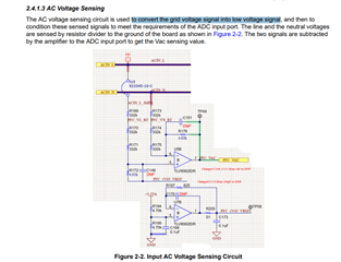
Please explain above schematic
i take different reading for different AC voltage as below.
| Sr.No. | VAC input voltage | voltage at TP49 means ADC dc Voltage |
| 1 | 100 VAC | 1.705V |
| 2 | 110 VAC | 1.715V |
| 3 | 120 VAC | 1.724V |
| 4 | 140 VAC | 1.748V |
| 5 | 150 VAC | 1.761V |
| 6 | 200 VAC | 1.823V |
| 7 | 220 VAC | 1.876V |
| 8 | 250 VAC | 1.936V |
| 9 | 300 VAC | 2.041V |
this reading is take by today
my concern is at 300 VAC voltage at TP49 is 2.041V.:is it correct ??
Babaji,
I'll let the TIDM-02010 experts take a look at your questions and hopefully they can help you with your future inquiries.
Regards,
Joseph
Hello,
I'll address two questions from your most recent posts.
pfcVars.VacRms_pu ==> AC RMS Voltage (VacRMS) in per-unit. Per-unit means it is a scale from 0 to 1, where 1 represents the maximum possible value, as defined by USER_PFC_ADC_FULL_SCALE_AC_VOLTAGE_V.
VacRms_pu = 0, the AC RMS Voltage = 0VacRms_pu = 1.0, the AC RMS Voltage = the value of USER_PFC_ADC_FULL_SCALE_AC_VOLTAGE_V
Regards,
Jason Osborn
Dear Jason,
while I debug the code then pfcVars.VacRms_pu=0.2865 reading occur .
How this pfcVars.VacRms_pu=0.2865 reading occur?? ,i want details explanation please provide as early as possible.
ODU_TI_Project_ADC_18012024.zip
main.c file
pfcVars.VacRms_pu this variable value can not update in while(1).
Please check code what is issue??
one more question is why ADC input voltage count is vary continuously?? .
Like count reading is 342->7->3562->1707->2149 like this count reading occur.
i used below formula:
#define USER_PFC_ADC_PU_SF (1.0f / 4096.0f)
#define USER_PFC_ADC_FULL_SCALE_AC_VOLTAGE_V (820.9119403f)
uint32_t* read_ADC_Value5=(uint32_t*)0x00000B01;
tempnewvalue5 = (*read_ADC_Value5);
VacBus=tempnewvalue5 * USER_PFC_ADC_PU_SF;
ADC_voltage = VacBus * VacBus;
Read_AC_voltage = ADC_voltage * USER_PFC_ADC_FULL_SCALE_AC_VOLTAGE_V;
Actual_AC_voltage = Read_AC_voltage ;
The Actual_AC_voltage reading continuously vary like 184VA,251VAC,284VA,84VAC,63VAC,27VAC,8VAc etc.
I'll let the TIDM-02010 experts take a look at your questions and hopefully they can help you with your future inquiries
Please answer as early as possible.
Dear Jason,
while I debug the code then pfcVars.VacRms_pu=0.2865 reading occur .
How this pfcVars.VacRms_pu=0.2865 reading occur?? ,i want details explanation please provide as early as possible.
ODU_TI_Project_ADC_18012024.zip
main.c file
pfcVars.VacRms_pu this variable value can not update in while(1).
Please check code what is issue??
one more question is why ADC input voltage count is vary continuously?? .
Like count reading is 342->7->3562->1707->2149 like this count reading occur.
i used below formula:
#define USER_PFC_ADC_PU_SF (1.0f / 4096.0f)
#define USER_PFC_ADC_FULL_SCALE_AC_VOLTAGE_V (820.9119403f)
uint32_t* read_ADC_Value5=(uint32_t*)0x00000B01;
tempnewvalue5 = (*read_ADC_Value5);
VacBus=tempnewvalue5 * USER_PFC_ADC_PU_SF;
ADC_voltage = VacBus * VacBus;
Read_AC_voltage = ADC_voltage * USER_PFC_ADC_FULL_SCALE_AC_VOLTAGE_V;
Actual_AC_voltage = Read_AC_voltage ;
The Actual_AC_voltage reading continuously vary like 184VA,251VAC,284VA,84VAC,63VAC,27VAC,8VAc etc.
Hello,
I'll answer each question I see individually.
All displayed behavior appears to be conceptually correct. What other specific errors (including the error description from the Problems view in CCS) or incorrect measurements (including both the measured value and the intended correct value, with units on both) are you facing?
Regards,
Jason Osborn
Because AC Voltage varies sinusoidally by definition, all resulting readings are also going to vary sinusoidally.
- This means that the ADC input voltage is going to vary sinusoidally. This can be seen by probing this voltage and displaying it on an oscilloscope. Alternatively, it can be seen by using the CCS graphing tool and graphing the ADC input vs time.
Dear Joseph,
right now pfcVars.VacRms_V this voltage not constant in my code
i want pfcVars.VacRms_V voltage constant in my expression window (it vary +- 5VAC )
how can do this constant ??
In tidm-02010 solution pfcVars.VacRms_V voltage constant 230VAC means it vary +- 5VAC
but right now in my code this pfcVars.VacRms_V voltage reading vary like 184VA,251VAC,284VA,84VAC,63VAC,27VAC,8VAc etc.
how can i achieve correct voltage reading.. what change i can do in my code??
Can you see my attached code ? if not please check & what's wrong in my code.
I'll let the TIDM-02010 experts take a look at your questions and hopefully they can help you with your future inquiries.
Dear Sir,
please provide details explanation above thread???
Hello,
Please note that I am the TIDM-02010 expert that Joseph referred to.
Unfortunately, we do not debug customer code bases. Individual files or excerpts are often helpful, but providing the entire project is not.
If the VacRms_V reading is varying, especially if it's varying sinusoidally, I would recommend that you double check the calculations you're using to determine the RMS value of your ADC input.
Very important reminder, if you're not using the TIDM-02010 hardware, you are necessarily going to need to change the hardware-related parameters in your code, including USER_PFC_ADC_FULL_SCALE_AC_VOLTAGE_V. Incorrect parameters cannot be expected to give correct output.
Regards,
Jason Osborn
Very important reminder, if you're not using the TIDM-02010 hardware, you are necessarily going to need to change the hardware-related parameters in your code, including USER_PFC_ADC_FULL_SCALE_AC_VOLTAGE_V. Incorrect parameters cannot be expected to give correct output.
Dear Joseph sir,
I am using TIDM-02010E32 HARDWARE.
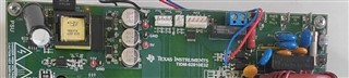 For your reference please check photo
//#############################################################################
//
// FILE:   empty_driverlib_main.c
//
//! \addtogroup driver_example_list
//! <h1>Empty Project Example</h1>
//!
//! This example is an empty project setup for Driverlib development.
//!
//
//#############################################################################
//
//
// $Copyright:
// Copyright (C) 2023 Texas Instruments Incorporated - http://www.ti.com/
//
// Redistribution and use in source and binary forms, with or without
// modification, are permitted provided that the following conditions
// are met:
//
//   Redistributions of source code must retain the above copyright
//   notice, this list of conditions and the following disclaimer.
//
//   Redistributions in binary form must reproduce the above copyright
//   notice, this list of conditions and the following disclaimer in the
//   documentation and/or other materials provided with the
//   distribution.
//
//   Neither the name of Texas Instruments Incorporated nor the names of
//   its contributors may be used to endorse or promote products derived
//   from this software without specific prior written permission.
//
// THIS SOFTWARE IS PROVIDED BY THE COPYRIGHT HOLDERS AND CONTRIBUTORS
// "AS IS" AND ANY EXPRESS OR IMPLIED WARRANTIES, INCLUDING, BUT NOT
// LIMITED TO, THE IMPLIED WARRANTIES OF MERCHANTABILITY AND FITNESS FOR
// A PARTICULAR PURPOSE ARE DISCLAIMED. IN NO EVENT SHALL THE COPYRIGHT
// OWNER OR CONTRIBUTORS BE LIABLE FOR ANY DIRECT, INDIRECT, INCIDENTAL,
// SPECIAL, EXEMPLARY, OR CONSEQUENTIAL DAMAGES (INCLUDING, BUT NOT
// LIMITED TO, PROCUREMENT OF SUBSTITUTE GOODS OR SERVICES; LOSS OF USE,
// DATA, OR PROFITS; OR BUSINESS INTERRUPTION) HOWEVER CAUSED AND ON ANY
// THEORY OF LIABILITY, WHETHER IN CONTRACT, STRICT LIABILITY, OR TORT
// (INCLUDING NEGLIGENCE OR OTHERWISE) ARISING IN ANY WAY OUT OF THE USE
// OF THIS SOFTWARE, EVEN IF ADVISED OF THE POSSIBILITY OF SUCH DAMAGE.
// $
//#############################################################################

//
// Included Files
//
#include "math.h"
#include "driverlib.h"
#include "device.h"
#include "board.h"
#include "c2000ware_libraries.h"

#include "adc.h"

//
// Main
//
//int16_t ADC_getTemperatureC(uint16_t tempResult, ADC_ReferenceMode refMode,float32_t vref);

float32_t tempResult,refMode,vref,Temp_Sensor_Ambient,Temp_Sensor1,value,Temp_Sensor_coils,Temp_Sensor_Pipes;
float32_t VacSen,resultBase,ppbNumber,ADCRESULT0,temp_data,mul_factor1,ADC_voltage;
//new 18-01-2024
//
typedef struct _FAULT_PFC_BITS_
{             // bits  description
    uint16_t overVoltageAC:1;       // 0  AC Bus Over Voltage Fault
    uint16_t underVoltageAC:1;      // 1  AC Bus Under Voltage Fault
    uint16_t overVoltageDC:1;       // 2  DC Bus Over Voltage Fault
    uint16_t underVoltageDC:1;      // 3  DC Bus Under Voltage Fault

    uint16_t moduleOverCurrent:1;   // 4  Hardware Over Current Fault Flag
    uint16_t overPeakCurrent:1;     // 5  internal CMPSS Over Current Fault Flag
    uint16_t overLoad:1;            // 6  Over Load Error
    uint16_t multiOverCurrent:1;    // 7  Multiple times over current

    uint16_t moduleOverTemp:1;      // 8  Power module over temperature Fault
    uint16_t shutDownVoltage:1;     // 9  DC bus over voltage to shut down PFC
    uint16_t reserve10:1;           // 10 Reserved
    uint16_t reserve11:1;           // 11 Reserved

    uint16_t reserve12:1;           // 12 Reserved
    uint16_t reserve13:1;           // 13 Reserved
    uint16_t reserve14:1;           // 14 Reserved
    uint16_t reserve15:1;           // 15 Reserved
} FAULT_PFC_BITS;

typedef union _FAULT_PFC_t
{
    uint16_t        all;
    FAULT_PFC_BITS  bit;
}FAULT_PFC_t;


// end 18-01-2024

typedef struct dcl_df22 {
    float32_t b0;   //!< b0
    float32_t b1;   //!< b1
    float32_t b2;   //!< b2
    float32_t a1;   //!< a1
    float32_t a2;   //!< a2
    float32_t x1;   //!< x1
    float32_t x2;   //!< x2
//    DCL_DF22_SPS *sps;  //!< Pointer to the shadow parameter set
//    DCL_CSS *css;   //!< Pointer to the common support structure
} DCL_DF22;
HAL_PFC_ADCData_t adcDataPFC;
PFC_Vars_t pfcVars;
DCL_PI   gv;
DCL_DF22 gi;


//New
POWER_MEAS_FAST measPower;

//-------------------------voltage & Current Reading-------------------
float32_t   Read_AC_current,Read_AC_voltage,Read_VDC_voltage,VacBus,Actual_AC_voltage;
//--------------------------------------------end----------------------
//----------Positive Temp-----------
#define BASEREADINGPOSITIVE 960     //;    //980//800
#define SPANCOUNTPOSITIVE 2744     //2020//1900
#define MAXTEMPPOSITIVE 85
//-----------Negative Temp-------
#define BASEREADINGNEGATIVE 54    //980//800
#define SPANCOUNTNEGATIVE 444     //2020//1900
#define MAXTEMPNEGATIVE 40

#define BASEREADINGCOILS 1520    //980//800
#define SPANCOUNTCOILS 1930     //2020//1900
#define MAXTEMPCOILS 50

//-----------------ADD_02012024---------
#define ADC_RESOLUTION_VALUE                (4096U)
#define LOG_10_E                            (0.434294f)
#define TEMP_T_25_K                         (298.15f)//kevin
//air temperature
#define TEMP_AIR_RES_T_25                   (10000U)//Ohm
#define TEMP_AIR_BETA                       (3950U)
#define TEMP_AIR_RES_GND                    (10000U)//Ohm

//coil temperature
#define TEMP_COIL_RES_T_25                  (10000U)//Ohm
#define TEMP_COIL_BETA                      (3950U)
#define TEMP_COIL_RES_GND                   (10000U)//Ohm

#define USER_PFC_ADC_FULL_SCALE_AC_VOLTAGE_V    (820.9119403f)
//! \brief Defines the maximum AC input voltage
#define USER_PFC_VOLTAGE_AC_IN_MAX_V    (265.0f)

//! \brief Defines the minimum AC input voltage
#define USER_PFC_VOLTAGE_AC_IN_MIN_V    (85.0f)
//! \brief Defines the maximum AC input voltage
#define USER_PFC_VOLTAGE_AC_IN_MAX_V    (265.0f)
//! defines ADC oversampling buffer size, 2
#define VAC_OVERSAMPLE_TIMES            (2)
//! \brief Defines the AC voltage scale factor with oversample for the system
#define USER_PFC_ADC_VAC_PU_SF          (1.0f / 4096.0f / (float32_t)VAC_OVERSAMPLE_TIMES)
//! \brief Defines the ADC scale factor for the system
#define USER_PFC_ADC_PU_SF              (1.0f / 4096.0f)
//! \brief Defines the number of ISR clock ticks per speed controller clock tick
#define USER_PFC_NUM_ISR_TICKS_PER_VOLTAGE_TICK     (5)
#define USER_PFC_ADC_FULL_SCALE_DC_VOLTAGE_V    (485.9432f)
// ----------- PFC Control Parameters ------------------------------------------
//! \brief Defines the voltage for enabling voltage loop
#define USER_PFC_ENABLE_VOLTAGE_LOOP_V          (15.0f)

//! \brief Defines the voltage for disabling voltage loop
#define USER_PFC_DISABLE_VOLTAGE_LOOP_V          (10.0f)

//! \brief Defines the voltage for enabling current loop
#define USER_PFC_ENABLE_CURRENT_LOOP_V          (20.0f)

//! \brief Defines the voltage for disabling current loop
#define USER_PFC_DISABLE_CURRENT_LOOP_V         (15.0f)

//! \brief Defines the ADC scale factor for the system
#define USER_PFC_ADC_PU_SF              (1.0f / 4096.0f)

#pragma CODE_SECTION(pfcCtrlISR, ".TI.ramfunc");

#pragma INTERRUPT(pfcCtrlISR, HPI)

unsigned int uiRowTemp;
//static uint32_t uiSubValue;
unsigned long uiTemp;
float fTempValue;
unsigned int tempnewvalue1;
unsigned int tempnewvalue2;
unsigned int tempnewvalue3;

unsigned int tempnewvalue4;
unsigned int tempnewvalue5;
unsigned int tempnewvalue6;

void initEPWM(void);//new
void initEPWM7(void);//new
static float ntc_sensor_get_temp(float res, uint16_t res_25, uint16_t beta);
static inline void HAL_readPFCADCData(HAL_PFC_ADCData_t *pADCData);
static inline void POWER_MEAS_FAST_run(POWER_MEAS_FAST *v);
static inline void HAL_ackPFCADCInt(void);
void runMotor1OffsetsCalculation(void);
void runPFCMainControl(void);

void main(void)
{
    uint32_t* read_ADC_Value=(uint32_t*)0x00000B40;
    uint32_t* read_ADC_Value2=(uint32_t*)0x00000B41;
    uint32_t* read_ADC_Value3=(uint32_t*)0x00000B42;

    uint32_t* read_ADC_Value4=(uint32_t*)0x00000B00;
    uint32_t* read_ADC_Value5=(uint32_t*)0x00000B01;
    uint32_t* read_ADC_Value6=(uint32_t*)0x00000B02;
    //
    // Initialize device clock and peripherals
    //
    Device_init();

    //
    // Disable pin locks and enable internal pull-ups.
    //
    Device_initGPIO();

    //
    // Initialize PIE and clear PIE registers. Disables CPU interrupts.
    //
    Interrupt_initModule();

    //
    // Initialize the PIE vector table with pointers to the shell Interrupt
    // Service Routines (ISR).
    //
    Interrupt_initVectorTable();

    //
    // PinMux and Peripheral Initialization
    //
    Board_init();

    initEPWM();//new
   // initEPWM7();//new
    // set the control parameters for PFC
       initPFCCtrlParameters();
    //
    // C2000Ware Library initialization
    //
    C2000Ware_libraries_init();

    //
    // Enable Global Interrupt (INTM) and real time interrupt (DBGM)
    //
    EINT;
    ERTM;
    EPWM_enableADCTrigger(EPWM1_BASE, EPWM_SOC_A);//new
    EPWM_setTimeBaseCounterMode(EPWM1_BASE, EPWM_COUNTER_MODE_UP);//new

    while(1)
    {
        tempnewvalue1 = (*read_ADC_Value);
        tempnewvalue2 = (*read_ADC_Value2);
        tempnewvalue3 = (*read_ADC_Value3);

        tempnewvalue4 = (*read_ADC_Value4);
        tempnewvalue5 = (*read_ADC_Value5);
        tempnewvalue6 = (*read_ADC_Value6);
//--------------------------------------Ambient sensor-------------------------------------------------
        fTempValue = (float)(ADC_RESOLUTION_VALUE - tempnewvalue1);
        fTempValue *= (TEMP_AIR_RES_GND / tempnewvalue1);
        Temp_Sensor_Ambient = (float)ntc_sensor_get_temp(fTempValue, TEMP_AIR_RES_T_25, TEMP_AIR_BETA);
//-------------------------------------coil sensor------------------------------------------------------
        fTempValue = (float)(ADC_RESOLUTION_VALUE - tempnewvalue2);
        fTempValue *= (TEMP_COIL_RES_GND / tempnewvalue2);
        Temp_Sensor_coils = (float)ntc_sensor_get_temp(fTempValue, TEMP_COIL_RES_T_25, TEMP_COIL_BETA);
//-------------------------------------Pipe sensor------------------------------------------------------
        fTempValue = (float)(ADC_RESOLUTION_VALUE - tempnewvalue3);
        fTempValue *= (TEMP_COIL_RES_GND / tempnewvalue3);
        Temp_Sensor_Pipes = (float)ntc_sensor_get_temp(fTempValue, TEMP_COIL_RES_T_25, TEMP_COIL_BETA);
        //else((tempnewvalue2 < 15) || (tempnewvalue2 >= 3600))

        Read_AC_current  = tempnewvalue4 * 0.000166;  //15/4095  //Read_AC_current_Actual_measure=0.6
        //Read_AC_voltage = tempnewvalue5 * 0.083;   //340/4095=0.083
        Read_VDC_voltage = tempnewvalue6 * 0.118637;  //(485.9432f)/(4096.0F)

       //Actual_AC_voltage = Read_VDC_voltage / 1.414;   //340/4095=0.083

        //ADC_voltage=tempnewvalue5 * USER_PFC_ADC_PU_SF;

       VacBus=tempnewvalue5 * USER_PFC_ADC_PU_SF;//tempnewvalue5=342,1373,3550
        ADC_voltage = VacBus * VacBus;

        Read_AC_voltage = ADC_voltage * USER_PFC_ADC_FULL_SCALE_AC_VOLTAGE_V;

        //Read_AC_voltage = temp_data * USER_PFC_ADC_FULL_SCALE_AC_VOLTAGE_V;
        pfcVars.VacRms_V = pfcVars.VacRms_pu * USER_PFC_ADC_FULL_SCALE_AC_VOLTAGE_V;

    }
}
//New 18-01-2024
void runPFCMainControl(void)
{
    // set the comparator value
/*    HAL_setPFCCMPSSDACValue(halPFCHandle,
                            pfcVars.dacCMPValH, pfcVars.dacCMPValL);

    if(HAL_getPFCPwmEnableStatus(halPFCHandle) == true)
    {
        if(HAL_getPFCTripFaults(halPFCHandle) != 0)
        {
            pfcVars.faultPFCNow.bit.moduleOverCurrent = 1;
        }
    }

    pfcVars.faultPFCPrev.all |= pfcVars.faultPFCNow.all;

    pfcVars.faultPFCUse.all = pfcVars.faultPFCNow.all &
            pfcVars.faultPFCMask.all;

    if(pfcVars.faultPFCUse.all != 0)
    {
        pfcVars.flagEnablePFC = false;

        pfcVars.VdcTrajTraget = 0.0f;
        pfcVars.VdcTrajInt = 0.0f;
        pfcVars.flagFirstVoltageLoop = true;
    }

    if(pfcVars.flagClearFaults == true)
    {
        HAL_clearPFCFaultStatus(halPFCHandle);

        pfcVars.faultPFCNow.all = 0;
        pfcVars.flagClearFaults = false;
    }
*/
//    pfcVars.IacRms_A = pfcVars.IacRms_pu * USER_PFC_ADC_FULL_SCALE_CURRENT_A;
    pfcVars.VacRms_V = pfcVars.VacRms_pu * USER_PFC_ADC_FULL_SCALE_AC_VOLTAGE_V;
    pfcVars.PowerRms_W = pfcVars.IacRms_A * pfcVars.VacRms_V;
    return;
}

//New 16-01-2024
static inline void HAL_readPFCADCData(HAL_PFC_ADCData_t *pADCData)
{
    float32_t value;

    value = (float32_t)(ADC_readPPBResult(PFC_VAC_ADCRES_BASE, PFC_VAC1_ADC_PPB_NUM) +
            ADC_readPPBResult(PFC_VAC_ADCRES_BASE, PFC_VAC2_ADC_PPB_NUM));
    pADCData->VacSen = value * pADCData->voltageAC_sf;
}


//new add 15-01-2024

static inline void POWER_MEAS_FAST_run(POWER_MEAS_FAST *v)
{
    v->currSign = ( v->v > v->threshold) ? 1 : 0;
    v->vSqrSum = v->vSqrSum + (v->v * v->v);
    v->iSqrSum = v->iSqrSum + (v->i * v->i);

    v->nSamples++;
    v->zcd = 0;

    if((v->prevSign != v->currSign) && (v->currSign == 1))
    {
        // check if the nSamples are in the ball park of a real frequency
        // that can be on the grid, this is done by comparing the nSamples
        // with the max value and min value it can be for the
        // AC Grid Connection these Max and Min are initialized by the
        // user in the code
        if(v->nSamplesMin < v->nSamples )
        {
            float32_t inverse_nSamples = (1.0f) / ((float32_t)v->nSamples);
            float32_t sqrt_inverse_nSamples = sqrtf(inverse_nSamples);

            v->vRms = sqrtf(v->vSqrSum) * sqrt_inverse_nSamples;
            v->iRms = sqrtf(v->iSqrSum) * sqrt_inverse_nSamples;
            v->acFreq = v->sampleFreq * inverse_nSamples;

            v->vSqrSum = 0;
            v->iSqrSum = 0;

            v->jitterCount = 0;
            v->nSamples = 0;
            v->zcd = 1;
        }
        else
        {
            //
            // otherwise it may be jitter ignore this reading
            // but count the number of jitters you are getting
            // but do not count to infinity as then when the grid comes back
            // it will take too much time to wind down the jitter count
            //
            if(v->jitterCount < 30)
            {
                v->jitterCount++;
            }

            v->nSamples = 0;
        }
    }

    if((v->nSamples > v->nSamplesMax) || (v->jitterCount > 20))
    {
        // most certainly the AC voltage is not present
        v->vRms = 0;
        v->iRms = 0;
        v->acFreq = 0;

        v->vSqrSum = 0;
        v->iSqrSum = 0;

        v->nSamples = 0;
        v->jitterCount = 0;
        v->zcd = 0;
    }

    v->prevSign = v->currSign;
}

void initPFCCtrlParameters(void)
{
    // initialize the driver
//    halPFCHandle = HAL_PFC_init(&halPFC, sizeof(halPFC));

    // sets up peripherals for PFC
//    HAL_PFC_setParams(halPFCHandle);

//    adcDataPFC.currentAC_sf = USER_PFC_ADC_IAC_PU_SF;
//    adcDataPFC.voltageAC_sf = USER_PFC_ADC_VAC_PU_SF;
 //   adcDataPFC.voltageDC_sf = USER_PFC_ADC_VDC_PU_SF;

//    pfcVars.lpfVdcCoeff = USER_LPF_VDC_COEFF;
    adcDataPFC.voltageAC_sf = USER_PFC_ADC_VAC_PU_SF;

    pfcVars.invRmsSqrVminOverVmax = USER_PFC_VOLTAGE_AC_IN_MIN_V / USER_PFC_ADC_FULL_SCALE_AC_VOLTAGE_V;
    pfcVars.invRmsSqrVmin = USER_PFC_VOLTAGE_AC_IN_MIN_V / USER_PFC_ADC_FULL_SCALE_AC_VOLTAGE_V;
    pfcVars.IacRefVmaxOverVmin = USER_PFC_VOLTAGE_AC_IN_MAX_V / USER_PFC_VOLTAGE_AC_IN_MIN_V;

    pfcVars.invRmsSqrCoef = (USER_PFC_VOLTAGE_AC_IN_MIN_V * USER_PFC_VOLTAGE_AC_IN_MAX_V) /
                            (USER_PFC_ADC_FULL_SCALE_AC_VOLTAGE_V * USER_PFC_ADC_FULL_SCALE_AC_VOLTAGE_V);

//    pfcVars.VdcBusShutDown = USER_SHUTDOWN_VOLTAGE_PU;

//    pfcVars.overCurrent_A = USER_PFC_OVER_CURRENT_A;
//    pfcVars.IacPeak_pu = USER_PFC_PEAK_CURRENT_PU;

    pfcVars.IdcRef = 0.0f;

//    pfcVars.IdcRefSwILOff = USER_PFC_IL_MODE_OFF_VREF;
//    pfcVars.IdcRefSwILOn = USER_PFC_IL_MODE_ON_VREF;

//    pfcVars.VdcSet_V = USER_PFC_VOLTAGE_TRAGET_V;
//    pfcVars.VdcTrajTraget = USER_PFC_VOLTAGE_TRAGET_V / USER_PFC_ADC_FULL_SCALE_DC_VOLTAGE_V;
    pfcVars.VdcTrajInt = 0.0f;
//    pfcVars.VdcTrajRate = USER_PFC_VOLTAGE_TRAJ_RATE_PU;

    pfcVars.dacCMPValH = 1024U;
    pfcVars.dacCMPValH = 0U;

//    pfcVars.faultPFCMask.all = PFC_FAULT_MASK_SET;

    pfcVars.flagEnablePFC = false;
    pfcVars.flagEnableCurrentLoop = false;
    pfcVars.flagEnableVoltageLoop = false;
    pfcVars.flagFirstVoltageLoop = false;
    pfcVars.flagEnableChangeGain = true;

    pfcVars.flagEnableILMode = true;
/*
    pfcCtrlVars.overVoltageFault_ACV = USER_OVER_VOLTAGE_FAULT_ACV;
    pfcCtrlVars.overVoltageNorm_ACV = USER_OVER_VOLTAGE_NORM_ACV;
    pfcCtrlVars.underVoltageFault_ACV = USER_UNDER_VOLTAGE_FAULT_ACV;
    pfcCtrlVars.underVoltageNorm_ACV = USER_UNDER_VOLTAGE_NORM_ACV;

    pfcCtrlVars.overVoltageFault_DCV = USER_OVER_VOLTAGE_FAULT_DCV;
    pfcCtrlVars.overVoltageNorm_DCV = USER_OVER_VOLTAGE_NORM_DCV;
    pfcCtrlVars.underVoltageFault_DCV = USER_UNDER_VOLTAGE_FAULT_DCV;
    pfcCtrlVars.underVoltageNorm_DCV = USER_UNDER_VOLTAGE_NORM_DCV;

    pfcCtrlVars.overCurrentFault_A = USER_PFC_OVER_CURRENT_A;
    pfcCtrlVars.overLoadFault_W = USER_PFC_OVER_LOAD_W;

    pfcCtrlVars.voltageAcFaultTimeSet = USER_PFC_VOLTAGE_AC_FAULT_TIME_SET;
    pfcCtrlVars.voltageDcFaultTimeSet = USER_PFC_VOLTAGE_DC_FAULT_TIME_SET;
    pfcCtrlVars.voltageDcFaultTimeSet = USER_PFC_OVER_LOAD_FAULT_TIME_SET;

*/
 //   pfcCtrlVars.overCurrentFaultTimesSet = USER_PFC_OVER_CURRENT_FAULT_TIMES_SET;

    pfcVars.VdcBus_pu = 0.0f;

    pfcVars.VacComp_V = 180.0f;
    pfcVars.IacCompFactor = 1.0f;
    pfcVars.IdcmCompFactor = 1.0f;

    pfcVars.VacRmsGainThs_V = 200.0f;

    pfcVars.IdcRefGainThsHV = 0.45f;
    pfcVars.IdcRefGainThsLV = 0.22f;

    pfcVars.IdcRefMaxSet = 0.95f;       // 0~95% of maximum current(PU)
    pfcVars.dutyOutMaxSet = 0.90f;      // 0~90% of maximum duty cycle

    //sine analyzer initialization
//    POWER_MEAS_FAST_reset(&measPower);

//    measPower.sampleFreq = USER_PFC_MEASURE_FREQ_Hz;
//    measPower.threshold  = USER_PFC_MEASURE_THRESHOLD_PU;

 //   measPower.nSamplesMax = USER_PFC_MEASURE_FREQ_Hz /
//                            USER_UNIVERSAL_GRID_MIN_FREQ;

 //   measPower.nSamplesMin = USER_PFC_MEASURE_FREQ_Hz /
 //                           USER_UNIVERSAL_GRID_MAX_FREQ;

 //   DCL_resetPI(&gv);

//    gv.Kp = (CNTL_2p2z_B0_10 - CNTL_2p2z_B1_10) * 1.0f;
//    gv.Ki = (CNTL_2p2z_B0_10 + CNTL_2p2z_B1_10) * 1.0f;

    gv.Umax = pfcVars.IdcRefMaxSet;
    gv.Umin = 0.0f;

/*    DCL_resetDF22(&gi);

    gi.b2   = CNTL_2p2z_B2_3;
    gi.b1   = CNTL_2p2z_B1_3;
    gi.b0   = CNTL_2p2z_B0_3;
    gi.a2   = CNTL_2p2z_A2_3;
    gi.a1   = CNTL_2p2z_A1_3;*/

    pfcVars.indexCurrentGain = 3;
    return;
}
static float ntc_sensor_get_temp(float res, uint16_t res_25, uint16_t beta)
{
    float temp = 1 / (1 / TEMP_T_25_K + (log10((float)res/res_25) / LOG_10_E / beta));
    temp -= 273.15;
    return temp;
}
//
__interrupt void INT_myADCA_1_ISR(void)
{
    ADC_clearInterruptStatus(myADCA_BASE, ADC_INT_NUMBER1);
    if(true==ADC_getInterruptOverflowStatus(myADCA_BASE, ADC_INT_NUMBER1))
    {
        ADC_clearInterruptOverflowStatus(myADCA_BASE, ADC_INT_NUMBER1);
        ADC_clearInterruptStatus(myADCA_BASE, ADC_INT_NUMBER1);
    }
  //  Interrupt_clearACKGroup(INT_myADCA_1_INTERRUPT_ACK_GROUP); //add comment 19-01-2024
 }
// End of File
/*
__interrupt void pfcCtrlISR(void)
{
    // Place ISR code here....
    ADC_clearInterruptStatus(PFC_MTRS_BASE, ADC_INT_NUMBER2);
    if(true==ADC_getInterruptOverflowStatus(PFC_MTRS_BASE, ADC_INT_NUMBER2))
    {
        ADC_clearInterruptOverflowStatus(PFC_MTRS_BASE, ADC_INT_NUMBER2);
        ADC_clearInterruptStatus(PFC_MTRS_BASE, ADC_INT_NUMBER2);
    }
    Interrupt_clearACKGroup(INT_PFC_MTRS_2_INTERRUPT_ACK_GROUP);
}
*/
__interrupt void motor1CtrlISR(void)
{
    // Place ISR code here....
    ADC_clearInterruptStatus(PFC_MTRS_BASE, ADC_INT_NUMBER3);
    if(true==ADC_getInterruptOverflowStatus(PFC_MTRS_BASE, ADC_INT_NUMBER3))
    {
        ADC_clearInterruptOverflowStatus(PFC_MTRS_BASE, ADC_INT_NUMBER3);
        ADC_clearInterruptStatus(PFC_MTRS_BASE, ADC_INT_NUMBER3);
    }
    Interrupt_clearACKGroup(INT_PFC_MTRS_3_INTERRUPT_ACK_GROUP);
} // end of mainISR() function


__interrupt void motor2CtrlISR(void)
{
    // Place ISR code here....


    ADC_clearInterruptStatus(PFC_MTRS_BASE, ADC_INT_NUMBER4);
    if(true==ADC_getInterruptOverflowStatus(PFC_MTRS_BASE, ADC_INT_NUMBER4))
    {
        ADC_clearInterruptOverflowStatus(PFC_MTRS_BASE, ADC_INT_NUMBER4);
        ADC_clearInterruptStatus(PFC_MTRS_BASE, ADC_INT_NUMBER4);
    }
    Interrupt_clearACKGroup(INT_PFC_MTRS_4_INTERRUPT_ACK_GROUP);
}

//
// initEPWM - Function to configure ePWM1 to generate the SOC.
//
void initEPWM(void)
{
    //
    // Disable SOCA
    //
    EPWM_disableADCTrigger(EPWM1_BASE, EPWM_SOC_A);
    //
    // Configure the SOC to occur on the first up-count event
    //
    EPWM_setADCTriggerSource(EPWM1_BASE, EPWM_SOC_A, EPWM_SOC_TBCTR_U_CMPA);
    EPWM_setADCTriggerEventPrescale(EPWM1_BASE, EPWM_SOC_A, 1);
    // Set the compare A value to 1000 and the period to 1999
    // Assuming ePWM clock is 100MHz, this would give 50kHz sampling
    // 50MHz ePWM clock would give 25kHz sampling, etc.
    // The sample rate can also be modulated by changing the ePWM period
    // directly (ensure that the compare A value is less than the period).
    //
    EPWM_setCounterCompareValue(EPWM1_BASE, EPWM_COUNTER_COMPARE_A, 1000);
    EPWM_setTimeBasePeriod(EPWM1_BASE, 1999);
    //
    // Set the local ePWM module clock divider to /1
    //
    EPWM_setClockPrescaler(EPWM1_BASE,
                           EPWM_CLOCK_DIVIDER_1,
                           EPWM_HSCLOCK_DIVIDER_1);
    //
    // Freeze the counter
    //
    EPWM_setTimeBaseCounterMode(EPWM1_BASE, EPWM_COUNTER_MODE_STOP_FREEZE);
}

//----------------------new--------------

__interrupt void pfcCtrlISR(void)
{
    pfcVars.ISRCount++;

    // acknowledge the interrupt of PFC
    HAL_ackPFCADCInt();

    // Interleaved PFC using DMA for Iac, 4 times average
    // read the ADC data with offsets
    HAL_readPFCADCData(&adcDataPFC);        // ILPFC

    //new ---------------19-01-2024------------
#if !defined(HVMTRPFC_REV1P1) && !defined(DMCPFC_REV1P0)
            adcDataPFC.VacBus = (float32_t)ADC_readResult(PFC_VAC_ADCRES_BASE,
                                      PFC_VAC_ADC_SOC_NUM) * USER_PFC_ADC_PU_SF; //1/4096
#endif // !HVMTRPFC_REV1P1 && !DMCPFC_REV1P0

#if defined(ILPFC_DCH_EN)
    // convert acbus current
     if(pfcVars.flagEnableILMode == true)
     {
         adcDataPFC.IacBus = adcDataPFC.currentAC_sf *
                 ((float32_t)(ADC_readPPBResult(PFC_IAC_ADCRES_BASE, PFC_IAC1_ADC_PPB_NUM) +
                 ADC_readPPBResult(PFC_IAC_ADCRES_BASE, PFC_IAC2_ADC_PPB_NUM)));
     }
     else
     {
#if defined(SPPFC_CHA_EN)
         adcDataPFC.IacBus = adcDataPFC.currentAC_sf * 2.0f *
                 ((float32_t)(ADC_readPPBResult(PFC_IAC_ADCRES_BASE, PFC_IAC1_ADC_PPB_NUM)));
#elif defined(SPPFC_CHB_EN)
         adcDataPFC.IacBus = adcDataPFC.currentAC_sf * 2.0f *
                 ((float32_t)(ADC_readPPBResult(PFC_IAC_ADCRES_BASE, PFC_IAC2_ADC_PPB_NUM)));
#endif      // SPPFC_CHA_EN || SPPFC_CHB_EN
     }
#elif defined(SPPFC_CHA_EN)
     // convert acbus current
      adcDataPFC.IacBus = adcDataPFC.currentAC_sf * 2.0f *
              ((float32_t)(ADC_readPPBResult(PFC_IAC_ADCRES_BASE, PFC_IAC1_ADC_PPB_NUM)));
#elif defined(SPPFC_CHB_EN)
      // convert acbus current
       adcDataPFC.IacBus = adcDataPFC.currentAC_sf * 2.0f *
               ((float32_t)(ADC_readPPBResult(PFC_IAC_ADCRES_BASE, PFC_IAC2_ADC_PPB_NUM)));
//#else      // !(SPPFC_CHA_EN || SPPFC_CHB_EN)
//#error Not select a right PFC output mode
#endif      // !(SPPFC_CHA_EN || SPPFC_CHB_EN)

    adcDataPFC.IacBus = (adcDataPFC.IacBus < USER_PFC_ADC_PU_SF) ?
            USER_PFC_ADC_PU_SF : adcDataPFC.IacBus; // minimum positive current

    // calculate AC bus voltage
#if defined(HVMTRPFC_REV1P1) || defined(DMCPFC_REV0P1)
    adcDataPFC.ValBus = adcDataPFC.ValBus - adcDataPFC.offset_Vac;
    adcDataPFC.VanBus = adcDataPFC.VanBus - adcDataPFC.offset_Van;

    if(adcDataPFC.ValBus > adcDataPFC.VanBus)
    {
        adcDataPFC.VacBus = adcDataPFC.ValBus - adcDataPFC.VanBus;
    }
    else
    {
        adcDataPFC.VacBus = adcDataPFC.VanBus - adcDataPFC.ValBus;
    }
#else
    adcDataPFC.VacBus = fabsf(adcDataPFC.VacSen);
#endif  // !(HVMTRPFC_REV1P1 | DMCPFC_REV0P1)

#if defined(SFRA_ENABLE) && (SFRA_TEST_TYPE == SFRA_TEST_PFC)
    sfraNoiseInj_pu = 0.0f;
    sfraNoiseVpfc = 0.0f;
    sfraNoiseIpfc = 0.0f;

    sfraNoiseInj_pu = SFRA_F32_inject(0.0f);

    if(sfraTestLoop == SFRA_TEST_PFC_VOLTAGE)
    {
        sfraNoiseVpfc = sfraNoiseInj_pu;
    }
    else if(sfraTestLoop == SFRA_TEST_PFC_CURRENT)
    {
        sfraNoiseIpfc = sfraNoiseInj_pu;
    }
#endif  // (SFRA_ENABLE && SFRA_TEST_PFC)

    pfcVars.counterVoltage++;

    switch(pfcVars.counterVoltage)
    {
        case USER_PFC_NUM_ISR_TICKS_PER_VOLTAGE_TICK:       // 36kHz/5=7.2kHz
            // voltage loop
            if(pfcVars.flagEnableVoltageLoop == true)
            {
#if defined(SFRA_ENABLE) && (SFRA_TEST_TYPE == SFRA_TEST_PFC)
                pfcVars.IdcRefOut =
                    DCL_runPI_C4(&gv, pfcVars.VdcTrajInt + sfraNoiseVpfc, pfcVars.VdcBusLPF);
#else   // !(SFRA_ENABLE) && (SFRA_TEST_TYPE == SFRA_TEST_PFC)
//                pfcVars.IdcRefOut =
//                       DCL_runPI_C4(&gv, pfcVars.VdcTrajInt, pfcVars.VdcBus_pu); //only
#endif  // !(SFRA_ENABLE) && (SFRA_TEST_TYPE == SFRA_TEST_PFC)

            }
            else    // pfcVars.flagEnableVoltageLoop == false
            {
                gv.i6 = 1.0f;
                gv.i10 = gv.i11 = 0.0f;

                pfcVars.IdcRefOut = 0.0;
            }

#if(PFC_BUILDLEVEL == PFC_LEVEL_4)
            pfcVars.IdcRef = pfcVars.IdcRefOut;
#endif
            pfcVars.counterVoltage = 0;

            break;

        case 1: // twice voltage control loop frequency
            // 3.130 = (1.0 / minimum voltage)^2, 48VAC
            pfcVars.VinvSqr = pfcVars.invRmsSqrCoef / (pfcVars.VacRms_pu * pfcVars.VacRms_pu);
            pfcVars.VinvSqr = (pfcVars.VinvSqr > 3.130f) ? 3.130f : pfcVars.VinvSqr;

            break;

        case 2: // twice voltage control loop frequency
            //Calculate RMS input voltage and input frequency, 7.2kHz
            measPower.i = adcDataPFC.IacBus;
            measPower.v = adcDataPFC.VacBus;

            POWER_MEAS_FAST_run(&measPower);

            pfcVars.IacRms_pu = measPower.iRms;
            pfcVars.VacRms_pu = measPower.vRms;

            //Divided by 2 because the signal is rectified
            pfcVars.FreqAc_Hz = measPower.acFreq * 0.5f;
            break;
        case 3:
            pfcVars.VdcBus_V = adcDataPFC.VdcBus * USER_PFC_ADC_FULL_SCALE_DC_VOLTAGE_V;

            // convert dc bus voltage from pu to SI unit
            pfcVars.VdcBusLPF = pfcVars.VdcBusLPF +
                    (adcDataPFC.VdcBus - pfcVars.VdcBusLPF) * pfcVars.lpfVdcCoeff;

            pfcVars.VdcBusLPF_V = pfcVars.VdcBusLPF * USER_PFC_ADC_FULL_SCALE_DC_VOLTAGE_V;

            // run notch filter
#if !defined(NOTCH_FILTER)
            pfcVars.VdcBus_pu = pfcVars.VdcBusLPF;
#else   // NOTCH_FILTER
            FILTER_NOTCH_set_in(filterNotchHandle, pfcVars.VdcBusLPF);
            FILTER_NOTCH_run(filterNotchHandle, filterCoeffHandle);
            pfcVars.VdcBusNotch = FILTER_NOTCH_get_out(filterNotchHandle);
            pfcVars.VdcBus_pu = pfcVars.VdcBusNotch;
#endif   // NOTCH_FILTER
            break;
        case 4:
            // ramp control
            if(pfcVars.flagEnablePFC == true)
            {
    #if(PFC_BUILDLEVEL >= PFC_LEVEL_3)
                if(pfcVars.VdcBus_V > USER_PFC_ENABLE_CURRENT_LOOP_V)
                {
                    pfcVars.flagEnableCurrentLoop = true;
                }
                else if(pfcVars.VdcBus_V < USER_PFC_DISABLE_CURRENT_LOOP_V)
                {
                    pfcVars.flagEnableCurrentLoop = false;
                }
    #endif

    #if(PFC_BUILDLEVEL == PFC_LEVEL_4)
                if(pfcVars.VacRms_V >= USER_PFC_ENABLE_VOLTAGE_LOOP_V)
                {
                    pfcVars.flagEnableVoltageLoop = true;
                }
                else if(pfcVars.VacRms_V < USER_PFC_DISABLE_VOLTAGE_LOOP_V)
                {
                    pfcVars.flagEnableVoltageLoop = false;
                }
    #endif

                if(pfcVars.flagFirstVoltageLoop == true)
                {
                    pfcVars.IacRef = adcDataPFC.IacBus;
                    pfcVars.VdcTrajInt = pfcVars.VdcBusLPF;

                    pfcVars.flagFirstVoltageLoop = false;
                }

                float32_t VdcError = pfcVars.VdcTrajTraget - pfcVars.VdcTrajInt;

                if(VdcError > pfcVars.VdcTrajRate)
                {
                    pfcVars.VdcTrajInt = pfcVars.VdcTrajTraget + pfcVars.VdcTrajRate;
                }
                else if(VdcError < -pfcVars.VdcTrajRate)
                {
                    pfcVars.VdcTrajInt = pfcVars.VdcTrajTraget - pfcVars.VdcTrajRate;
                }
                else
                {
                    pfcVars.VdcTrajInt = pfcVars.VdcTrajTraget;
                    pfcVars.flagStatePFC = true;
                }
            }
            else    // pfcVars.flagEnablePFC == false
            {
                pfcVars.IdcRef = 0.0f;

                pfcVars.IacRef = adcDataPFC.IacBus;
                pfcVars.VdcTrajInt = pfcVars.VdcBusLPF;
                pfcVars.dutyOut = 0.0;

                pfcVars.flagEnableCurrentLoop = false;
                pfcVars.flagEnableVoltageLoop = false;
                pfcVars.flagFirstVoltageLoop = true;
                pfcVars.flagStatePFC = false;
            }
            break;

        default:
            break;
    }

    pfcVars.IacRef = pfcVars.VinvSqr * adcDataPFC.VacBus * pfcVars.IdcRef;

    pfcVars.IacRef = (pfcVars.IacRef > pfcVars.IacPeak_pu) ?
            pfcVars.IacPeak_pu : pfcVars.IacRef;

    pfcVars.IacRef = (pfcVars.IacRef < 0.0f) ? 0.0f : pfcVars.IacRef;

    pfcVars.IacSen = adcDataPFC.IacBus;

    /*
    // run current loop controller
    if(pfcVars.flagEnableCurrentLoop == true)
    {
#if defined(SFRA_ENABLE) && (SFRA_TEST_TYPE == SFRA_TEST_PFC)

        pfcVars.IacError = (pfcVars.IacRef + sfraNoiseIpfc) - pfcVars.IacSen;

        pfcVars.giOut = DCL_runDF22_C1(&gi, pfcVars.IacError);
#else
        pfcVars.IacError = pfcVars.IacRef - pfcVars.IacSen;

//        pfcVars.giOut = DCL_runDF22_C1(&gi, pfcVars.IacError);
#endif  // (SFRA_ENABLE) && (SFRA_TEST_TYPE == SFRA_TEST_PFC)

        pfcVars.dutyOut = (pfcVars.giOut > pfcVars.dutyOutMaxSet) ? pfcVars.dutyOutMaxSet : pfcVars.giOut;
        pfcVars.dutyOut = (pfcVars.giOut < 0.0f) ? 0.0f : pfcVars.giOut;

        gi.x1 = pfcVars.dutyOut;        // store the output for next cycle
    }
    else
    {
        gi.x1 = gi.x2 = 0.0f;

#if(PFC_BUILDLEVEL >= PFC_LEVEL_3)
        pfcVars.dutyOut = 0.0;
#endif
    }

#if(PFC_BUILDLEVEL >= PFC_LEVEL_3)
    // over peak voltage protection
    if(adcDataPFC.VdcBus > pfcVars.VdcBusShutDown)      // 410.0VDC, set a right value according to the system
    {
//        pfcVars.faultPFCNow.bit.shutDownVoltage = 1; //only comment
        pfcVars.dutyOut = 0.0f;

        gv.i10 = gv.i10 * 0.75f;
        gv.i11 = 0.0f;
    }
#endif
// 18-01

#if(PFC_BUILDLEVEL == PFC_LEVEL_1)
    // output 50%
//    pwmDataPFC.dutyValue = 0.5f; //18-01
#elif(PFC_BUILDLEVEL >= PFC_LEVEL_2)
    // manual set the duty
    pwmDataPFC.dutyValue = pfcVars.dutyOut;
#endif

    // write the PWM compare values
   // HAL_writePFCPWMData(halPFCHandle, &pwmDataPFC);
*/
    return;
} // end of mainISR() function

static inline void HAL_ackPFCADCInt(void)
{
    // clear the ADC interrupt flag
    ADC_clearInterruptStatus(PFC_MTRS_BASE, ADC_INT_NUMBER2);

    // Acknowledge interrupt from PIE group
    Interrupt_clearACKGroup(INT_PFC_MTRS_2_INTERRUPT_ACK_GROUP);

    return;
} // end of HAL_ackPFCInt() function
Please check code & suggest .
Very important reminder, if you're not using the TIDM-02010 hardware, you are necessarily going to need to change the hardware-related parameters in your code, including USER_PFC_ADC_FULL_SCALE_AC_VOLTAGE_V. Incorrect parameters cannot be expected to give correct output.
Dear Joseph sir,
I am using TIDM-02010E32 HARDWARE.
For your reference please check photo
//#############################################################################
//
// FILE:   empty_driverlib_main.c
//
//! \addtogroup driver_example_list
//! <h1>Empty Project Example</h1>
//!
//! This example is an empty project setup for Driverlib development.
//!
//
//#############################################################################
//
//
// $Copyright:
// Copyright (C) 2023 Texas Instruments Incorporated - http://www.ti.com/
//
// Redistribution and use in source and binary forms, with or without
// modification, are permitted provided that the following conditions
// are met:
//
//   Redistributions of source code must retain the above copyright
//   notice, this list of conditions and the following disclaimer.
//
//   Redistributions in binary form must reproduce the above copyright
//   notice, this list of conditions and the following disclaimer in the
//   documentation and/or other materials provided with the
//   distribution.
//
//   Neither the name of Texas Instruments Incorporated nor the names of
//   its contributors may be used to endorse or promote products derived
//   from this software without specific prior written permission.
//
// THIS SOFTWARE IS PROVIDED BY THE COPYRIGHT HOLDERS AND CONTRIBUTORS
// "AS IS" AND ANY EXPRESS OR IMPLIED WARRANTIES, INCLUDING, BUT NOT
// LIMITED TO, THE IMPLIED WARRANTIES OF MERCHANTABILITY AND FITNESS FOR
// A PARTICULAR PURPOSE ARE DISCLAIMED. IN NO EVENT SHALL THE COPYRIGHT
// OWNER OR CONTRIBUTORS BE LIABLE FOR ANY DIRECT, INDIRECT, INCIDENTAL,
// SPECIAL, EXEMPLARY, OR CONSEQUENTIAL DAMAGES (INCLUDING, BUT NOT
// LIMITED TO, PROCUREMENT OF SUBSTITUTE GOODS OR SERVICES; LOSS OF USE,
// DATA, OR PROFITS; OR BUSINESS INTERRUPTION) HOWEVER CAUSED AND ON ANY
// THEORY OF LIABILITY, WHETHER IN CONTRACT, STRICT LIABILITY, OR TORT
// (INCLUDING NEGLIGENCE OR OTHERWISE) ARISING IN ANY WAY OUT OF THE USE
// OF THIS SOFTWARE, EVEN IF ADVISED OF THE POSSIBILITY OF SUCH DAMAGE.
// $
//#############################################################################

//
// Included Files
//
#include "math.h"
#include "driverlib.h"
#include "device.h"
#include "board.h"
#include "c2000ware_libraries.h"

#include "adc.h"

//
// Main
//
//int16_t ADC_getTemperatureC(uint16_t tempResult, ADC_ReferenceMode refMode,float32_t vref);

float32_t tempResult,refMode,vref,Temp_Sensor_Ambient,Temp_Sensor1,value,Temp_Sensor_coils,Temp_Sensor_Pipes;
float32_t VacSen,resultBase,ppbNumber,ADCRESULT0,temp_data,mul_factor1,ADC_voltage;
//new 18-01-2024
//
typedef struct _FAULT_PFC_BITS_
{             // bits  description
    uint16_t overVoltageAC:1;       // 0  AC Bus Over Voltage Fault
    uint16_t underVoltageAC:1;      // 1  AC Bus Under Voltage Fault
    uint16_t overVoltageDC:1;       // 2  DC Bus Over Voltage Fault
    uint16_t underVoltageDC:1;      // 3  DC Bus Under Voltage Fault

    uint16_t moduleOverCurrent:1;   // 4  Hardware Over Current Fault Flag
    uint16_t overPeakCurrent:1;     // 5  internal CMPSS Over Current Fault Flag
    uint16_t overLoad:1;            // 6  Over Load Error
    uint16_t multiOverCurrent:1;    // 7  Multiple times over current

    uint16_t moduleOverTemp:1;      // 8  Power module over temperature Fault
    uint16_t shutDownVoltage:1;     // 9  DC bus over voltage to shut down PFC
    uint16_t reserve10:1;           // 10 Reserved
    uint16_t reserve11:1;           // 11 Reserved

    uint16_t reserve12:1;           // 12 Reserved
    uint16_t reserve13:1;           // 13 Reserved
    uint16_t reserve14:1;           // 14 Reserved
    uint16_t reserve15:1;           // 15 Reserved
} FAULT_PFC_BITS;

typedef union _FAULT_PFC_t
{
    uint16_t        all;
    FAULT_PFC_BITS  bit;
}FAULT_PFC_t;


// end 18-01-2024

typedef struct dcl_df22 {
    float32_t b0;   //!< b0
    float32_t b1;   //!< b1
    float32_t b2;   //!< b2
    float32_t a1;   //!< a1
    float32_t a2;   //!< a2
    float32_t x1;   //!< x1
    float32_t x2;   //!< x2
//    DCL_DF22_SPS *sps;  //!< Pointer to the shadow parameter set
//    DCL_CSS *css;   //!< Pointer to the common support structure
} DCL_DF22;
HAL_PFC_ADCData_t adcDataPFC;
PFC_Vars_t pfcVars;
DCL_PI   gv;
DCL_DF22 gi;


//New
POWER_MEAS_FAST measPower;

//-------------------------voltage & Current Reading-------------------
float32_t   Read_AC_current,Read_AC_voltage,Read_VDC_voltage,VacBus,Actual_AC_voltage;
//--------------------------------------------end----------------------
//----------Positive Temp-----------
#define BASEREADINGPOSITIVE 960     //;    //980//800
#define SPANCOUNTPOSITIVE 2744     //2020//1900
#define MAXTEMPPOSITIVE 85
//-----------Negative Temp-------
#define BASEREADINGNEGATIVE 54    //980//800
#define SPANCOUNTNEGATIVE 444     //2020//1900
#define MAXTEMPNEGATIVE 40

#define BASEREADINGCOILS 1520    //980//800
#define SPANCOUNTCOILS 1930     //2020//1900
#define MAXTEMPCOILS 50

//-----------------ADD_02012024---------
#define ADC_RESOLUTION_VALUE                (4096U)
#define LOG_10_E                            (0.434294f)
#define TEMP_T_25_K                         (298.15f)//kevin
//air temperature
#define TEMP_AIR_RES_T_25                   (10000U)//Ohm
#define TEMP_AIR_BETA                       (3950U)
#define TEMP_AIR_RES_GND                    (10000U)//Ohm

//coil temperature
#define TEMP_COIL_RES_T_25                  (10000U)//Ohm
#define TEMP_COIL_BETA                      (3950U)
#define TEMP_COIL_RES_GND                   (10000U)//Ohm

#define USER_PFC_ADC_FULL_SCALE_AC_VOLTAGE_V    (820.9119403f)
//! \brief Defines the maximum AC input voltage
#define USER_PFC_VOLTAGE_AC_IN_MAX_V    (265.0f)

//! \brief Defines the minimum AC input voltage
#define USER_PFC_VOLTAGE_AC_IN_MIN_V    (85.0f)
//! \brief Defines the maximum AC input voltage
#define USER_PFC_VOLTAGE_AC_IN_MAX_V    (265.0f)
//! defines ADC oversampling buffer size, 2
#define VAC_OVERSAMPLE_TIMES            (2)
//! \brief Defines the AC voltage scale factor with oversample for the system
#define USER_PFC_ADC_VAC_PU_SF          (1.0f / 4096.0f / (float32_t)VAC_OVERSAMPLE_TIMES)
//! \brief Defines the ADC scale factor for the system
#define USER_PFC_ADC_PU_SF              (1.0f / 4096.0f)
//! \brief Defines the number of ISR clock ticks per speed controller clock tick
#define USER_PFC_NUM_ISR_TICKS_PER_VOLTAGE_TICK     (5)
#define USER_PFC_ADC_FULL_SCALE_DC_VOLTAGE_V    (485.9432f)
// ----------- PFC Control Parameters ------------------------------------------
//! \brief Defines the voltage for enabling voltage loop
#define USER_PFC_ENABLE_VOLTAGE_LOOP_V          (15.0f)

//! \brief Defines the voltage for disabling voltage loop
#define USER_PFC_DISABLE_VOLTAGE_LOOP_V          (10.0f)

//! \brief Defines the voltage for enabling current loop
#define USER_PFC_ENABLE_CURRENT_LOOP_V          (20.0f)

//! \brief Defines the voltage for disabling current loop
#define USER_PFC_DISABLE_CURRENT_LOOP_V         (15.0f)

//! \brief Defines the ADC scale factor for the system
#define USER_PFC_ADC_PU_SF              (1.0f / 4096.0f)

#pragma CODE_SECTION(pfcCtrlISR, ".TI.ramfunc");

#pragma INTERRUPT(pfcCtrlISR, HPI)

unsigned int uiRowTemp;
//static uint32_t uiSubValue;
unsigned long uiTemp;
float fTempValue;
unsigned int tempnewvalue1;
unsigned int tempnewvalue2;
unsigned int tempnewvalue3;

unsigned int tempnewvalue4;
unsigned int tempnewvalue5;
unsigned int tempnewvalue6;

void initEPWM(void);//new
void initEPWM7(void);//new
static float ntc_sensor_get_temp(float res, uint16_t res_25, uint16_t beta);
static inline void HAL_readPFCADCData(HAL_PFC_ADCData_t *pADCData);
static inline void POWER_MEAS_FAST_run(POWER_MEAS_FAST *v);
static inline void HAL_ackPFCADCInt(void);
void runMotor1OffsetsCalculation(void);
void runPFCMainControl(void);

void main(void)
{
    uint32_t* read_ADC_Value=(uint32_t*)0x00000B40;
    uint32_t* read_ADC_Value2=(uint32_t*)0x00000B41;
    uint32_t* read_ADC_Value3=(uint32_t*)0x00000B42;

    uint32_t* read_ADC_Value4=(uint32_t*)0x00000B00;
    uint32_t* read_ADC_Value5=(uint32_t*)0x00000B01;
    uint32_t* read_ADC_Value6=(uint32_t*)0x00000B02;
    //
    // Initialize device clock and peripherals
    //
    Device_init();

    //
    // Disable pin locks and enable internal pull-ups.
    //
    Device_initGPIO();

    //
    // Initialize PIE and clear PIE registers. Disables CPU interrupts.
    //
    Interrupt_initModule();

    //
    // Initialize the PIE vector table with pointers to the shell Interrupt
    // Service Routines (ISR).
    //
    Interrupt_initVectorTable();

    //
    // PinMux and Peripheral Initialization
    //
    Board_init();

    initEPWM();//new
   // initEPWM7();//new
    // set the control parameters for PFC
       initPFCCtrlParameters();
    //
    // C2000Ware Library initialization
    //
    C2000Ware_libraries_init();

    //
    // Enable Global Interrupt (INTM) and real time interrupt (DBGM)
    //
    EINT;
    ERTM;
    EPWM_enableADCTrigger(EPWM1_BASE, EPWM_SOC_A);//new
    EPWM_setTimeBaseCounterMode(EPWM1_BASE, EPWM_COUNTER_MODE_UP);//new

    while(1)
    {
        tempnewvalue1 = (*read_ADC_Value);
        tempnewvalue2 = (*read_ADC_Value2);
        tempnewvalue3 = (*read_ADC_Value3);

        tempnewvalue4 = (*read_ADC_Value4);
        tempnewvalue5 = (*read_ADC_Value5);
        tempnewvalue6 = (*read_ADC_Value6);
//--------------------------------------Ambient sensor-------------------------------------------------
        fTempValue = (float)(ADC_RESOLUTION_VALUE - tempnewvalue1);
        fTempValue *= (TEMP_AIR_RES_GND / tempnewvalue1);
        Temp_Sensor_Ambient = (float)ntc_sensor_get_temp(fTempValue, TEMP_AIR_RES_T_25, TEMP_AIR_BETA);
//-------------------------------------coil sensor------------------------------------------------------
        fTempValue = (float)(ADC_RESOLUTION_VALUE - tempnewvalue2);
        fTempValue *= (TEMP_COIL_RES_GND / tempnewvalue2);
        Temp_Sensor_coils = (float)ntc_sensor_get_temp(fTempValue, TEMP_COIL_RES_T_25, TEMP_COIL_BETA);
//-------------------------------------Pipe sensor------------------------------------------------------
        fTempValue = (float)(ADC_RESOLUTION_VALUE - tempnewvalue3);
        fTempValue *= (TEMP_COIL_RES_GND / tempnewvalue3);
        Temp_Sensor_Pipes = (float)ntc_sensor_get_temp(fTempValue, TEMP_COIL_RES_T_25, TEMP_COIL_BETA);
        //else((tempnewvalue2 < 15) || (tempnewvalue2 >= 3600))

        Read_AC_current  = tempnewvalue4 * 0.000166;  //15/4095  //Read_AC_current_Actual_measure=0.6
        //Read_AC_voltage = tempnewvalue5 * 0.083;   //340/4095=0.083
        Read_VDC_voltage = tempnewvalue6 * 0.118637;  //(485.9432f)/(4096.0F)

       //Actual_AC_voltage = Read_VDC_voltage / 1.414;   //340/4095=0.083

        //ADC_voltage=tempnewvalue5 * USER_PFC_ADC_PU_SF;

       VacBus=tempnewvalue5 * USER_PFC_ADC_PU_SF;//tempnewvalue5=342,1373,3550
        ADC_voltage = VacBus * VacBus;

        Read_AC_voltage = ADC_voltage * USER_PFC_ADC_FULL_SCALE_AC_VOLTAGE_V;

        //Read_AC_voltage = temp_data * USER_PFC_ADC_FULL_SCALE_AC_VOLTAGE_V;
        pfcVars.VacRms_V = pfcVars.VacRms_pu * USER_PFC_ADC_FULL_SCALE_AC_VOLTAGE_V;

    }
}
//New 18-01-2024
void runPFCMainControl(void)
{
    // set the comparator value
/*    HAL_setPFCCMPSSDACValue(halPFCHandle,
                            pfcVars.dacCMPValH, pfcVars.dacCMPValL);

    if(HAL_getPFCPwmEnableStatus(halPFCHandle) == true)
    {
        if(HAL_getPFCTripFaults(halPFCHandle) != 0)
        {
            pfcVars.faultPFCNow.bit.moduleOverCurrent = 1;
        }
    }

    pfcVars.faultPFCPrev.all |= pfcVars.faultPFCNow.all;

    pfcVars.faultPFCUse.all = pfcVars.faultPFCNow.all &
            pfcVars.faultPFCMask.all;

    if(pfcVars.faultPFCUse.all != 0)
    {
        pfcVars.flagEnablePFC = false;

        pfcVars.VdcTrajTraget = 0.0f;
        pfcVars.VdcTrajInt = 0.0f;
        pfcVars.flagFirstVoltageLoop = true;
    }

    if(pfcVars.flagClearFaults == true)
    {
        HAL_clearPFCFaultStatus(halPFCHandle);

        pfcVars.faultPFCNow.all = 0;
        pfcVars.flagClearFaults = false;
    }
*/
//    pfcVars.IacRms_A = pfcVars.IacRms_pu * USER_PFC_ADC_FULL_SCALE_CURRENT_A;
    pfcVars.VacRms_V = pfcVars.VacRms_pu * USER_PFC_ADC_FULL_SCALE_AC_VOLTAGE_V;
    pfcVars.PowerRms_W = pfcVars.IacRms_A * pfcVars.VacRms_V;
    return;
}

//New 16-01-2024
static inline void HAL_readPFCADCData(HAL_PFC_ADCData_t *pADCData)
{
    float32_t value;

    value = (float32_t)(ADC_readPPBResult(PFC_VAC_ADCRES_BASE, PFC_VAC1_ADC_PPB_NUM) +
            ADC_readPPBResult(PFC_VAC_ADCRES_BASE, PFC_VAC2_ADC_PPB_NUM));
    pADCData->VacSen = value * pADCData->voltageAC_sf;
}


//new add 15-01-2024

static inline void POWER_MEAS_FAST_run(POWER_MEAS_FAST *v)
{
    v->currSign = ( v->v > v->threshold) ? 1 : 0;
    v->vSqrSum = v->vSqrSum + (v->v * v->v);
    v->iSqrSum = v->iSqrSum + (v->i * v->i);

    v->nSamples++;
    v->zcd = 0;

    if((v->prevSign != v->currSign) && (v->currSign == 1))
    {
        // check if the nSamples are in the ball park of a real frequency
        // that can be on the grid, this is done by comparing the nSamples
        // with the max value and min value it can be for the
        // AC Grid Connection these Max and Min are initialized by the
        // user in the code
        if(v->nSamplesMin < v->nSamples )
        {
            float32_t inverse_nSamples = (1.0f) / ((float32_t)v->nSamples);
            float32_t sqrt_inverse_nSamples = sqrtf(inverse_nSamples);

            v->vRms = sqrtf(v->vSqrSum) * sqrt_inverse_nSamples;
            v->iRms = sqrtf(v->iSqrSum) * sqrt_inverse_nSamples;
            v->acFreq = v->sampleFreq * inverse_nSamples;

            v->vSqrSum = 0;
            v->iSqrSum = 0;

            v->jitterCount = 0;
            v->nSamples = 0;
            v->zcd = 1;
        }
        else
        {
            //
            // otherwise it may be jitter ignore this reading
            // but count the number of jitters you are getting
            // but do not count to infinity as then when the grid comes back
            // it will take too much time to wind down the jitter count
            //
            if(v->jitterCount < 30)
            {
                v->jitterCount++;
            }

            v->nSamples = 0;
        }
    }

    if((v->nSamples > v->nSamplesMax) || (v->jitterCount > 20))
    {
        // most certainly the AC voltage is not present
        v->vRms = 0;
        v->iRms = 0;
        v->acFreq = 0;

        v->vSqrSum = 0;
        v->iSqrSum = 0;

        v->nSamples = 0;
        v->jitterCount = 0;
        v->zcd = 0;
    }

    v->prevSign = v->currSign;
}

void initPFCCtrlParameters(void)
{
    // initialize the driver
//    halPFCHandle = HAL_PFC_init(&halPFC, sizeof(halPFC));

    // sets up peripherals for PFC
//    HAL_PFC_setParams(halPFCHandle);

//    adcDataPFC.currentAC_sf = USER_PFC_ADC_IAC_PU_SF;
//    adcDataPFC.voltageAC_sf = USER_PFC_ADC_VAC_PU_SF;
 //   adcDataPFC.voltageDC_sf = USER_PFC_ADC_VDC_PU_SF;

//    pfcVars.lpfVdcCoeff = USER_LPF_VDC_COEFF;
    adcDataPFC.voltageAC_sf = USER_PFC_ADC_VAC_PU_SF;

    pfcVars.invRmsSqrVminOverVmax = USER_PFC_VOLTAGE_AC_IN_MIN_V / USER_PFC_ADC_FULL_SCALE_AC_VOLTAGE_V;
    pfcVars.invRmsSqrVmin = USER_PFC_VOLTAGE_AC_IN_MIN_V / USER_PFC_ADC_FULL_SCALE_AC_VOLTAGE_V;
    pfcVars.IacRefVmaxOverVmin = USER_PFC_VOLTAGE_AC_IN_MAX_V / USER_PFC_VOLTAGE_AC_IN_MIN_V;

    pfcVars.invRmsSqrCoef = (USER_PFC_VOLTAGE_AC_IN_MIN_V * USER_PFC_VOLTAGE_AC_IN_MAX_V) /
                            (USER_PFC_ADC_FULL_SCALE_AC_VOLTAGE_V * USER_PFC_ADC_FULL_SCALE_AC_VOLTAGE_V);

//    pfcVars.VdcBusShutDown = USER_SHUTDOWN_VOLTAGE_PU;

//    pfcVars.overCurrent_A = USER_PFC_OVER_CURRENT_A;
//    pfcVars.IacPeak_pu = USER_PFC_PEAK_CURRENT_PU;

    pfcVars.IdcRef = 0.0f;

//    pfcVars.IdcRefSwILOff = USER_PFC_IL_MODE_OFF_VREF;
//    pfcVars.IdcRefSwILOn = USER_PFC_IL_MODE_ON_VREF;

//    pfcVars.VdcSet_V = USER_PFC_VOLTAGE_TRAGET_V;
//    pfcVars.VdcTrajTraget = USER_PFC_VOLTAGE_TRAGET_V / USER_PFC_ADC_FULL_SCALE_DC_VOLTAGE_V;
    pfcVars.VdcTrajInt = 0.0f;
//    pfcVars.VdcTrajRate = USER_PFC_VOLTAGE_TRAJ_RATE_PU;

    pfcVars.dacCMPValH = 1024U;
    pfcVars.dacCMPValH = 0U;

//    pfcVars.faultPFCMask.all = PFC_FAULT_MASK_SET;

    pfcVars.flagEnablePFC = false;
    pfcVars.flagEnableCurrentLoop = false;
    pfcVars.flagEnableVoltageLoop = false;
    pfcVars.flagFirstVoltageLoop = false;
    pfcVars.flagEnableChangeGain = true;

    pfcVars.flagEnableILMode = true;
/*
    pfcCtrlVars.overVoltageFault_ACV = USER_OVER_VOLTAGE_FAULT_ACV;
    pfcCtrlVars.overVoltageNorm_ACV = USER_OVER_VOLTAGE_NORM_ACV;
    pfcCtrlVars.underVoltageFault_ACV = USER_UNDER_VOLTAGE_FAULT_ACV;
    pfcCtrlVars.underVoltageNorm_ACV = USER_UNDER_VOLTAGE_NORM_ACV;

    pfcCtrlVars.overVoltageFault_DCV = USER_OVER_VOLTAGE_FAULT_DCV;
    pfcCtrlVars.overVoltageNorm_DCV = USER_OVER_VOLTAGE_NORM_DCV;
    pfcCtrlVars.underVoltageFault_DCV = USER_UNDER_VOLTAGE_FAULT_DCV;
    pfcCtrlVars.underVoltageNorm_DCV = USER_UNDER_VOLTAGE_NORM_DCV;

    pfcCtrlVars.overCurrentFault_A = USER_PFC_OVER_CURRENT_A;
    pfcCtrlVars.overLoadFault_W = USER_PFC_OVER_LOAD_W;

    pfcCtrlVars.voltageAcFaultTimeSet = USER_PFC_VOLTAGE_AC_FAULT_TIME_SET;
    pfcCtrlVars.voltageDcFaultTimeSet = USER_PFC_VOLTAGE_DC_FAULT_TIME_SET;
    pfcCtrlVars.voltageDcFaultTimeSet = USER_PFC_OVER_LOAD_FAULT_TIME_SET;

*/
 //   pfcCtrlVars.overCurrentFaultTimesSet = USER_PFC_OVER_CURRENT_FAULT_TIMES_SET;

    pfcVars.VdcBus_pu = 0.0f;

    pfcVars.VacComp_V = 180.0f;
    pfcVars.IacCompFactor = 1.0f;
    pfcVars.IdcmCompFactor = 1.0f;

    pfcVars.VacRmsGainThs_V = 200.0f;

    pfcVars.IdcRefGainThsHV = 0.45f;
    pfcVars.IdcRefGainThsLV = 0.22f;

    pfcVars.IdcRefMaxSet = 0.95f;       // 0~95% of maximum current(PU)
    pfcVars.dutyOutMaxSet = 0.90f;      // 0~90% of maximum duty cycle

    //sine analyzer initialization
//    POWER_MEAS_FAST_reset(&measPower);

//    measPower.sampleFreq = USER_PFC_MEASURE_FREQ_Hz;
//    measPower.threshold  = USER_PFC_MEASURE_THRESHOLD_PU;

 //   measPower.nSamplesMax = USER_PFC_MEASURE_FREQ_Hz /
//                            USER_UNIVERSAL_GRID_MIN_FREQ;

 //   measPower.nSamplesMin = USER_PFC_MEASURE_FREQ_Hz /
 //                           USER_UNIVERSAL_GRID_MAX_FREQ;

 //   DCL_resetPI(&gv);

//    gv.Kp = (CNTL_2p2z_B0_10 - CNTL_2p2z_B1_10) * 1.0f;
//    gv.Ki = (CNTL_2p2z_B0_10 + CNTL_2p2z_B1_10) * 1.0f;

    gv.Umax = pfcVars.IdcRefMaxSet;
    gv.Umin = 0.0f;

/*    DCL_resetDF22(&gi);

    gi.b2   = CNTL_2p2z_B2_3;
    gi.b1   = CNTL_2p2z_B1_3;
    gi.b0   = CNTL_2p2z_B0_3;
    gi.a2   = CNTL_2p2z_A2_3;
    gi.a1   = CNTL_2p2z_A1_3;*/

    pfcVars.indexCurrentGain = 3;
    return;
}
static float ntc_sensor_get_temp(float res, uint16_t res_25, uint16_t beta)
{
    float temp = 1 / (1 / TEMP_T_25_K + (log10((float)res/res_25) / LOG_10_E / beta));
    temp -= 273.15;
    return temp;
}
//
__interrupt void INT_myADCA_1_ISR(void)
{
    ADC_clearInterruptStatus(myADCA_BASE, ADC_INT_NUMBER1);
    if(true==ADC_getInterruptOverflowStatus(myADCA_BASE, ADC_INT_NUMBER1))
    {
        ADC_clearInterruptOverflowStatus(myADCA_BASE, ADC_INT_NUMBER1);
        ADC_clearInterruptStatus(myADCA_BASE, ADC_INT_NUMBER1);
    }
  //  Interrupt_clearACKGroup(INT_myADCA_1_INTERRUPT_ACK_GROUP); //add comment 19-01-2024
 }
// End of File
/*
__interrupt void pfcCtrlISR(void)
{
    // Place ISR code here....
    ADC_clearInterruptStatus(PFC_MTRS_BASE, ADC_INT_NUMBER2);
    if(true==ADC_getInterruptOverflowStatus(PFC_MTRS_BASE, ADC_INT_NUMBER2))
    {
        ADC_clearInterruptOverflowStatus(PFC_MTRS_BASE, ADC_INT_NUMBER2);
        ADC_clearInterruptStatus(PFC_MTRS_BASE, ADC_INT_NUMBER2);
    }
    Interrupt_clearACKGroup(INT_PFC_MTRS_2_INTERRUPT_ACK_GROUP);
}
*/
__interrupt void motor1CtrlISR(void)
{
    // Place ISR code here....
    ADC_clearInterruptStatus(PFC_MTRS_BASE, ADC_INT_NUMBER3);
    if(true==ADC_getInterruptOverflowStatus(PFC_MTRS_BASE, ADC_INT_NUMBER3))
    {
        ADC_clearInterruptOverflowStatus(PFC_MTRS_BASE, ADC_INT_NUMBER3);
        ADC_clearInterruptStatus(PFC_MTRS_BASE, ADC_INT_NUMBER3);
    }
    Interrupt_clearACKGroup(INT_PFC_MTRS_3_INTERRUPT_ACK_GROUP);
} // end of mainISR() function


__interrupt void motor2CtrlISR(void)
{
    // Place ISR code here....


    ADC_clearInterruptStatus(PFC_MTRS_BASE, ADC_INT_NUMBER4);
    if(true==ADC_getInterruptOverflowStatus(PFC_MTRS_BASE, ADC_INT_NUMBER4))
    {
        ADC_clearInterruptOverflowStatus(PFC_MTRS_BASE, ADC_INT_NUMBER4);
        ADC_clearInterruptStatus(PFC_MTRS_BASE, ADC_INT_NUMBER4);
    }
    Interrupt_clearACKGroup(INT_PFC_MTRS_4_INTERRUPT_ACK_GROUP);
}

//
// initEPWM - Function to configure ePWM1 to generate the SOC.
//
void initEPWM(void)
{
    //
    // Disable SOCA
    //
    EPWM_disableADCTrigger(EPWM1_BASE, EPWM_SOC_A);
    //
    // Configure the SOC to occur on the first up-count event
    //
    EPWM_setADCTriggerSource(EPWM1_BASE, EPWM_SOC_A, EPWM_SOC_TBCTR_U_CMPA);
    EPWM_setADCTriggerEventPrescale(EPWM1_BASE, EPWM_SOC_A, 1);
    // Set the compare A value to 1000 and the period to 1999
    // Assuming ePWM clock is 100MHz, this would give 50kHz sampling
    // 50MHz ePWM clock would give 25kHz sampling, etc.
    // The sample rate can also be modulated by changing the ePWM period
    // directly (ensure that the compare A value is less than the period).
    //
    EPWM_setCounterCompareValue(EPWM1_BASE, EPWM_COUNTER_COMPARE_A, 1000);
    EPWM_setTimeBasePeriod(EPWM1_BASE, 1999);
    //
    // Set the local ePWM module clock divider to /1
    //
    EPWM_setClockPrescaler(EPWM1_BASE,
                           EPWM_CLOCK_DIVIDER_1,
                           EPWM_HSCLOCK_DIVIDER_1);
    //
    // Freeze the counter
    //
    EPWM_setTimeBaseCounterMode(EPWM1_BASE, EPWM_COUNTER_MODE_STOP_FREEZE);
}

//----------------------new--------------

__interrupt void pfcCtrlISR(void)
{
    pfcVars.ISRCount++;

    // acknowledge the interrupt of PFC
    HAL_ackPFCADCInt();

    // Interleaved PFC using DMA for Iac, 4 times average
    // read the ADC data with offsets
    HAL_readPFCADCData(&adcDataPFC);        // ILPFC

    //new ---------------19-01-2024------------
#if !defined(HVMTRPFC_REV1P1) && !defined(DMCPFC_REV1P0)
            adcDataPFC.VacBus = (float32_t)ADC_readResult(PFC_VAC_ADCRES_BASE,
                                      PFC_VAC_ADC_SOC_NUM) * USER_PFC_ADC_PU_SF; //1/4096
#endif // !HVMTRPFC_REV1P1 && !DMCPFC_REV1P0

#if defined(ILPFC_DCH_EN)
    // convert acbus current
     if(pfcVars.flagEnableILMode == true)
     {
         adcDataPFC.IacBus = adcDataPFC.currentAC_sf *
                 ((float32_t)(ADC_readPPBResult(PFC_IAC_ADCRES_BASE, PFC_IAC1_ADC_PPB_NUM) +
                 ADC_readPPBResult(PFC_IAC_ADCRES_BASE, PFC_IAC2_ADC_PPB_NUM)));
     }
     else
     {
#if defined(SPPFC_CHA_EN)
         adcDataPFC.IacBus = adcDataPFC.currentAC_sf * 2.0f *
                 ((float32_t)(ADC_readPPBResult(PFC_IAC_ADCRES_BASE, PFC_IAC1_ADC_PPB_NUM)));
#elif defined(SPPFC_CHB_EN)
         adcDataPFC.IacBus = adcDataPFC.currentAC_sf * 2.0f *
                 ((float32_t)(ADC_readPPBResult(PFC_IAC_ADCRES_BASE, PFC_IAC2_ADC_PPB_NUM)));
#endif      // SPPFC_CHA_EN || SPPFC_CHB_EN
     }
#elif defined(SPPFC_CHA_EN)
     // convert acbus current
      adcDataPFC.IacBus = adcDataPFC.currentAC_sf * 2.0f *
              ((float32_t)(ADC_readPPBResult(PFC_IAC_ADCRES_BASE, PFC_IAC1_ADC_PPB_NUM)));
#elif defined(SPPFC_CHB_EN)
      // convert acbus current
       adcDataPFC.IacBus = adcDataPFC.currentAC_sf * 2.0f *
               ((float32_t)(ADC_readPPBResult(PFC_IAC_ADCRES_BASE, PFC_IAC2_ADC_PPB_NUM)));
//#else      // !(SPPFC_CHA_EN || SPPFC_CHB_EN)
//#error Not select a right PFC output mode
#endif      // !(SPPFC_CHA_EN || SPPFC_CHB_EN)

    adcDataPFC.IacBus = (adcDataPFC.IacBus < USER_PFC_ADC_PU_SF) ?
            USER_PFC_ADC_PU_SF : adcDataPFC.IacBus; // minimum positive current

    // calculate AC bus voltage
#if defined(HVMTRPFC_REV1P1) || defined(DMCPFC_REV0P1)
    adcDataPFC.ValBus = adcDataPFC.ValBus - adcDataPFC.offset_Vac;
    adcDataPFC.VanBus = adcDataPFC.VanBus - adcDataPFC.offset_Van;

    if(adcDataPFC.ValBus > adcDataPFC.VanBus)
    {
        adcDataPFC.VacBus = adcDataPFC.ValBus - adcDataPFC.VanBus;
    }
    else
    {
        adcDataPFC.VacBus = adcDataPFC.VanBus - adcDataPFC.ValBus;
    }
#else
    adcDataPFC.VacBus = fabsf(adcDataPFC.VacSen);
#endif  // !(HVMTRPFC_REV1P1 | DMCPFC_REV0P1)

#if defined(SFRA_ENABLE) && (SFRA_TEST_TYPE == SFRA_TEST_PFC)
    sfraNoiseInj_pu = 0.0f;
    sfraNoiseVpfc = 0.0f;
    sfraNoiseIpfc = 0.0f;

    sfraNoiseInj_pu = SFRA_F32_inject(0.0f);

    if(sfraTestLoop == SFRA_TEST_PFC_VOLTAGE)
    {
        sfraNoiseVpfc = sfraNoiseInj_pu;
    }
    else if(sfraTestLoop == SFRA_TEST_PFC_CURRENT)
    {
        sfraNoiseIpfc = sfraNoiseInj_pu;
    }
#endif  // (SFRA_ENABLE && SFRA_TEST_PFC)

    pfcVars.counterVoltage++;

    switch(pfcVars.counterVoltage)
    {
        case USER_PFC_NUM_ISR_TICKS_PER_VOLTAGE_TICK:       // 36kHz/5=7.2kHz
            // voltage loop
            if(pfcVars.flagEnableVoltageLoop == true)
            {
#if defined(SFRA_ENABLE) && (SFRA_TEST_TYPE == SFRA_TEST_PFC)
                pfcVars.IdcRefOut =
                    DCL_runPI_C4(&gv, pfcVars.VdcTrajInt + sfraNoiseVpfc, pfcVars.VdcBusLPF);
#else   // !(SFRA_ENABLE) && (SFRA_TEST_TYPE == SFRA_TEST_PFC)
//                pfcVars.IdcRefOut =
//                       DCL_runPI_C4(&gv, pfcVars.VdcTrajInt, pfcVars.VdcBus_pu); //only
#endif  // !(SFRA_ENABLE) && (SFRA_TEST_TYPE == SFRA_TEST_PFC)

            }
            else    // pfcVars.flagEnableVoltageLoop == false
            {
                gv.i6 = 1.0f;
                gv.i10 = gv.i11 = 0.0f;

                pfcVars.IdcRefOut = 0.0;
            }

#if(PFC_BUILDLEVEL == PFC_LEVEL_4)
            pfcVars.IdcRef = pfcVars.IdcRefOut;
#endif
            pfcVars.counterVoltage = 0;

            break;

        case 1: // twice voltage control loop frequency
            // 3.130 = (1.0 / minimum voltage)^2, 48VAC
            pfcVars.VinvSqr = pfcVars.invRmsSqrCoef / (pfcVars.VacRms_pu * pfcVars.VacRms_pu);
            pfcVars.VinvSqr = (pfcVars.VinvSqr > 3.130f) ? 3.130f : pfcVars.VinvSqr;

            break;

        case 2: // twice voltage control loop frequency
            //Calculate RMS input voltage and input frequency, 7.2kHz
            measPower.i = adcDataPFC.IacBus;
            measPower.v = adcDataPFC.VacBus;

            POWER_MEAS_FAST_run(&measPower);

            pfcVars.IacRms_pu = measPower.iRms;
            pfcVars.VacRms_pu = measPower.vRms;

            //Divided by 2 because the signal is rectified
            pfcVars.FreqAc_Hz = measPower.acFreq * 0.5f;
            break;
        case 3:
            pfcVars.VdcBus_V = adcDataPFC.VdcBus * USER_PFC_ADC_FULL_SCALE_DC_VOLTAGE_V;

            // convert dc bus voltage from pu to SI unit
            pfcVars.VdcBusLPF = pfcVars.VdcBusLPF +
                    (adcDataPFC.VdcBus - pfcVars.VdcBusLPF) * pfcVars.lpfVdcCoeff;

            pfcVars.VdcBusLPF_V = pfcVars.VdcBusLPF * USER_PFC_ADC_FULL_SCALE_DC_VOLTAGE_V;

            // run notch filter
#if !defined(NOTCH_FILTER)
            pfcVars.VdcBus_pu = pfcVars.VdcBusLPF;
#else   // NOTCH_FILTER
            FILTER_NOTCH_set_in(filterNotchHandle, pfcVars.VdcBusLPF);
            FILTER_NOTCH_run(filterNotchHandle, filterCoeffHandle);
            pfcVars.VdcBusNotch = FILTER_NOTCH_get_out(filterNotchHandle);
            pfcVars.VdcBus_pu = pfcVars.VdcBusNotch;
#endif   // NOTCH_FILTER
            break;
        case 4:
            // ramp control
            if(pfcVars.flagEnablePFC == true)
            {
    #if(PFC_BUILDLEVEL >= PFC_LEVEL_3)
                if(pfcVars.VdcBus_V > USER_PFC_ENABLE_CURRENT_LOOP_V)
                {
                    pfcVars.flagEnableCurrentLoop = true;
                }
                else if(pfcVars.VdcBus_V < USER_PFC_DISABLE_CURRENT_LOOP_V)
                {
                    pfcVars.flagEnableCurrentLoop = false;
                }
    #endif

    #if(PFC_BUILDLEVEL == PFC_LEVEL_4)
                if(pfcVars.VacRms_V >= USER_PFC_ENABLE_VOLTAGE_LOOP_V)
                {
                    pfcVars.flagEnableVoltageLoop = true;
                }
                else if(pfcVars.VacRms_V < USER_PFC_DISABLE_VOLTAGE_LOOP_V)
                {
                    pfcVars.flagEnableVoltageLoop = false;
                }
    #endif

                if(pfcVars.flagFirstVoltageLoop == true)
                {
                    pfcVars.IacRef = adcDataPFC.IacBus;
                    pfcVars.VdcTrajInt = pfcVars.VdcBusLPF;

                    pfcVars.flagFirstVoltageLoop = false;
                }

                float32_t VdcError = pfcVars.VdcTrajTraget - pfcVars.VdcTrajInt;

                if(VdcError > pfcVars.VdcTrajRate)
                {
                    pfcVars.VdcTrajInt = pfcVars.VdcTrajTraget + pfcVars.VdcTrajRate;
                }
                else if(VdcError < -pfcVars.VdcTrajRate)
                {
                    pfcVars.VdcTrajInt = pfcVars.VdcTrajTraget - pfcVars.VdcTrajRate;
                }
                else
                {
                    pfcVars.VdcTrajInt = pfcVars.VdcTrajTraget;
                    pfcVars.flagStatePFC = true;
                }
            }
            else    // pfcVars.flagEnablePFC == false
            {
                pfcVars.IdcRef = 0.0f;

                pfcVars.IacRef = adcDataPFC.IacBus;
                pfcVars.VdcTrajInt = pfcVars.VdcBusLPF;
                pfcVars.dutyOut = 0.0;

                pfcVars.flagEnableCurrentLoop = false;
                pfcVars.flagEnableVoltageLoop = false;
                pfcVars.flagFirstVoltageLoop = true;
                pfcVars.flagStatePFC = false;
            }
            break;

        default:
            break;
    }

    pfcVars.IacRef = pfcVars.VinvSqr * adcDataPFC.VacBus * pfcVars.IdcRef;

    pfcVars.IacRef = (pfcVars.IacRef > pfcVars.IacPeak_pu) ?
            pfcVars.IacPeak_pu : pfcVars.IacRef;

    pfcVars.IacRef = (pfcVars.IacRef < 0.0f) ? 0.0f : pfcVars.IacRef;

    pfcVars.IacSen = adcDataPFC.IacBus;

    /*
    // run current loop controller
    if(pfcVars.flagEnableCurrentLoop == true)
    {
#if defined(SFRA_ENABLE) && (SFRA_TEST_TYPE == SFRA_TEST_PFC)

        pfcVars.IacError = (pfcVars.IacRef + sfraNoiseIpfc) - pfcVars.IacSen;

        pfcVars.giOut = DCL_runDF22_C1(&gi, pfcVars.IacError);
#else
        pfcVars.IacError = pfcVars.IacRef - pfcVars.IacSen;

//        pfcVars.giOut = DCL_runDF22_C1(&gi, pfcVars.IacError);
#endif  // (SFRA_ENABLE) && (SFRA_TEST_TYPE == SFRA_TEST_PFC)

        pfcVars.dutyOut = (pfcVars.giOut > pfcVars.dutyOutMaxSet) ? pfcVars.dutyOutMaxSet : pfcVars.giOut;
        pfcVars.dutyOut = (pfcVars.giOut < 0.0f) ? 0.0f : pfcVars.giOut;

        gi.x1 = pfcVars.dutyOut;        // store the output for next cycle
    }
    else
    {
        gi.x1 = gi.x2 = 0.0f;

#if(PFC_BUILDLEVEL >= PFC_LEVEL_3)
        pfcVars.dutyOut = 0.0;
#endif
    }

#if(PFC_BUILDLEVEL >= PFC_LEVEL_3)
    // over peak voltage protection
    if(adcDataPFC.VdcBus > pfcVars.VdcBusShutDown)      // 410.0VDC, set a right value according to the system
    {
//        pfcVars.faultPFCNow.bit.shutDownVoltage = 1; //only comment
        pfcVars.dutyOut = 0.0f;

        gv.i10 = gv.i10 * 0.75f;
        gv.i11 = 0.0f;
    }
#endif
// 18-01

#if(PFC_BUILDLEVEL == PFC_LEVEL_1)
    // output 50%
//    pwmDataPFC.dutyValue = 0.5f; //18-01
#elif(PFC_BUILDLEVEL >= PFC_LEVEL_2)
    // manual set the duty
    pwmDataPFC.dutyValue = pfcVars.dutyOut;
#endif

    // write the PWM compare values
   // HAL_writePFCPWMData(halPFCHandle, &pwmDataPFC);
*/
    return;
} // end of mainISR() function

static inline void HAL_ackPFCADCInt(void)
{
    // clear the ADC interrupt flag
    ADC_clearInterruptStatus(PFC_MTRS_BASE, ADC_INT_NUMBER2);

    // Acknowledge interrupt from PIE group
    Interrupt_clearACKGroup(INT_PFC_MTRS_2_INTERRUPT_ACK_GROUP);

    return;
} // end of HAL_ackPFCInt() function
Please check code & suggest .
I'll let the TIDM-02010 experts take a look at your questions and hopefully they can help you with your future inquiries.
Any update from last 6 Day no one can reply.
please check data as have already sended data.
please reply as early as possible.
Any update from last 6 Day no one can reply.
please check data as have already sended data.
please reply as early as possible.
Any Update ??
Apologies for the delay. I was unexpectedly out of office with a sickness and was unable to work.
Please note that we do not debug customer code bases. A 1000 line file can be a lot to go through, particularly when the source of the issue is uncertain.
That said, I do notice a couple things immediately in your main() function. In the future, I highly recommend providing short, specific excerpts of code to allow us to more easily assist you.
It's very possible that you're not getting valid ADC results due to the first two problems. You may, for example, be attempting to read the ADC results in the middle of the ADC attempting to write to the results register, resulting in junk data.
Regards,
Jason Osborn
Hi Jason,
i have add libraries file in my existing project from another project like D:\ODU\FW\ODU_FW_F2800137\tidm_02010_dmpfc_0013x\libraries.
i have try as per below pic..
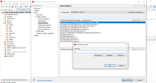
this way this file not link & generate error as below.
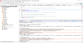
Sorry, I'm not certain what you're trying to do. What libraries are you trying to include?
Regards,
Jason Osborn
Dear Sir,
please resolved.
**** Build of configuration CPU1_RAM for project ODU_TI_ADC_Project ****
"C:\\ti\\ccs1250\\ccs\\utils\\bin\\gmake" -k -j 4 all -O
Building target: "ODU_TI_ADC_Project.out"
Invoking: C2000 Linker
"C:/ti/ccs1250/ccs/tools/compiler/ti-cgt-c2000_22.6.1.LTS/bin/cl2000" -v28 -ml -mt --cla_support=cla2 --float_support=fpu32 --tmu_support=tmu0 -O2 --opt_for_speed=3 --fp_mode=relaxed --advice:performance=all --define=DEBUG --define=RAM --define=_INLINE --define=_FLASH --define=_F280013x --define=_PMSM_FAST_LIB --define=SYSCONFIG_EN_N --define=NEST_INT_ENABLE --define=DMCPFC_REV3P2 --define=PFC_DISABLE_N --define=MOTOR1_DISABLE_N --define=MOTOR2_DISABLE_N --define=ILPFC_DCH_EN --define=ILPFC_SWM_EN_N --define=SPPFC_CHA_EN_N --define=SPPFC_CHB_EN_N --define=MOTOR1_ESMO_N --define=MOTOR2_FAST --define=MOTOR2_ESMO_N --define=MOTOR1_SSIPD_N --define=MOTOR1_MTPA_N --define=MOTOR1_FWC_N --define=MOTOR1_VIBCOMPA_N --define=MOTOR1_VIBCOMPT_N --define=DATALOGI4_EN_N --define=DATALOGF2_EN_N --define=DATALOG_PFC_N --define=DATALOG_MOTOR1_N --define=DATALOG_MOTOR2_N --define=DAC128S_ENABLE --define=DAC128S_SPIA --define=SFRA_ENABLE_N --define=CPUTIME_ENABLE_N --define=GPTEST_ENABLE_N --define=DEBUG_MONITOR_EN_N --define=MOTOR1_FAST --diag_suppress=10063 --diag_warning=225 --diag_wrap=off --display_error_number --gen_func_subsections=on --abi=eabi -z -m"ODU_TI_ADC_Project.map" --stack_size=0x100 --warn_sections -i"D:/ODU/FW/ODU_TI_Project_ADC_22122023/ODU_TI_ADC_Project/libraries/sfra" -i"D:/ODU/FW/ODU_TI_Project_ADC_22122023/ODU_TI_ADC_Project/libraries/observers/est_lib" -i"C:/ti/ccs1250/ccs/tools/compiler/ti-cgt-c2000_22.6.1.LTS/lib" -i"C:/ti/c2000/C2000Ware_5_00_00_00" -i"D:/ODU/FW/ODU_TI_Project_ADC_22122023/ODU_TI_ADC_Project/CPU1_RAM/syscfg" -i"C:/ti/ccs1250/ccs/tools/compiler/ti-cgt-c2000_22.6.1.LTS/include" --reread_libs --define=SFRA_ENABLE_N --diag_wrap=off --display_error_number --xml_link_info="ODU_TI_ADC_Project_linkInfo.xml" --entry_point=code_start --rom_model -o "ODU_TI_ADC_Project.out" "./syscfg/board.obj" "./syscfg/c2000ware_libraries.obj" "./main.obj" "./device/device.obj" "./device/f280013x_codestartbranch.obj" "./device/f280013x_globalvariabledefs.obj" "./device/driverlib/adc.obj" "./device/driverlib/asysctl.obj" "./device/driverlib/can.obj" "./device/driverlib/cmpss.obj" "./device/driverlib/cmpss_lite.obj" "./device/driverlib/cputimer.obj" "./device/driverlib/dcc.obj" "./device/driverlib/dcsm.obj" "./device/driverlib/ecap.obj" "./device/driverlib/epg.obj" "./device/driverlib/epwm.obj" "./device/driverlib/eqep.obj" "./device/driverlib/flash.obj" "./device/driverlib/gpio.obj" "./device/driverlib/hrpwm.obj" "./device/driverlib/i2c.obj" "./device/driverlib/interrupt.obj" "./device/driverlib/memcfg.obj" "./device/driverlib/sci.obj" "./device/driverlib/spi.obj" "./device/driverlib/sysctl.obj" "./device/driverlib/version.obj" "./device/driverlib/xbar.obj" "./libraries/control/DCL/c28/DCL_DF22_C1.obj" "./libraries/control/DCL/c28/DCL_PI_C1.obj" "./libraries/control/DCL/c28/DCL_PI_C4.obj" "./libraries/control/dclink_ss/dclink_ss.obj" "./libraries/control/mtpa/mtpa.obj" "./libraries/control/pi/pi.obj" "./libraries/control/vib_comp/vib_comp.obj" "./libraries/control/vs_freq/vs_freq.obj" "./libraries/dacs/dac128s085/dac128s085.obj" "./libraries/filter/filter_fo/filter_fo.obj" "./libraries/filter/filter_so/filter_so.obj" "./libraries/filter/notch/filter_notch.obj" "./libraries/filter/offset/offset.obj" "./libraries/observers/esmo/esmo.obj" "./libraries/observers/speedfr/speedfr.obj" "./libraries/observers/ssipd/ssipd.obj" "./libraries/sfra/sfra_gui.obj" "./libraries/sfra/sfra_gui_scicomms_driverlib.obj" "./libraries/transforms/clarke/clarke.obj" "./libraries/transforms/ipark/ipark.obj" "./libraries/transforms/park/park.obj" "./libraries/transforms/svgen/svgen.obj" "./libraries/transforms/svgen/svgen_current.obj" "./libraries/transforms/volts/volt_recons.obj" "./libraries/utilities/angle_gen/angle_gen.obj" "./libraries/utilities/cpu_time/cpu_time.obj" "./libraries/utilities/datalog/datalogIF.obj" "./libraries/utilities/traj/traj.obj" "./src_board/hal.obj" "./src_board/user_mtr1.obj" "./src_board/user_mtr2.obj" "./src_board/user_pfc.obj" "./src_control/motor1_drive.obj" "./src_control/motor2_drive.obj" "./src_control/motor_common.obj" "./src_control/pfc_ctrl.obj" "./src_sys/communication.obj" "./src_sys/systemcontrol.obj" "./src_sys/systemdisplay.obj" "../280013x_generic_ram_lnk.cmd" "C:/ti/c2000/C2000Ware_5_00_00_00/driverlib/f280013x/driverlib/ccs/Debug/driverlib.lib" "../device/driverlib.lib" "../device/f280013x_flash_lib.cmd" "../device/f280013x_headers_nonbios.cmd" "../device/driverlib/ccs/Debug/driverlib.lib" "../device/driverlib/ccs/Release/driverlib.lib" "../libraries/observers/est_lib/fast_full_lib.lib" "../libraries/observers/est_lib/fast_full_lib_coff.lib" "../libraries/observers/est_lib/fast_full_lib_eabi.lib" "../libraries/observers/est_lib/fast_pmsm_lib.lib" "../libraries/observers/est_lib/fast_pmsm_lib_coff.lib" "../libraries/observers/est_lib/fast_pmsm_lib_eabi.lib" "../libraries/observers/est_lib/fast_simple_lib.lib" "../libraries/observers/est_lib/fast_simple_lib_coff.lib" "../libraries/observers/est_lib/fast_simple_lib_eabi.lib" "../libraries/sfra/sfra_f32_tmu_eabi.lib" -lfast_pmsm_lib.lib -lc2000ware_libraries.cmd.genlibs -llibc.a
<Linking>
"../device/f280013x_flash_lib.cmd", line 37: error #10263: BEGIN memory range has already been specified
"../device/f280013x_flash_lib.cmd", line 38: error #10263: BOOT_RSVD memory range has already been specified
"../device/f280013x_flash_lib.cmd", line 38: error #10264: BOOT_RSVD memory range overlaps existing memory range BOOT_RSVD
"../device/f280013x_flash_lib.cmd", line 41: error #10264: RAMLS1P memory range overlaps existing memory range RAMLS1
"../device/f280013x_flash_lib.cmd", line 44: error #10263: RESET memory range has already been specified
"../device/f280013x_flash_lib.cmd", line 44: error #10264: RESET memory range overlaps existing memory range RESET
"../device/f280013x_flash_lib.cmd", line 48: error #10264: FLASHBANK0_BOOT memory range overlaps existing memory range FLASH_BANK0_SEC_0_7
"../device/f280013x_flash_lib.cmd", line 52: error #10264: FLASHBANK0_FAST memory range overlaps existing memory range FLASH_BANK0_SEC_8_15
"../device/f280013x_flash_lib.cmd", line 52: error #10264: FLASHBANK0_FAST memory range overlaps existing memory range FLASH_BANK0_SEC_16_23
"../device/f280013x_flash_lib.cmd", line 55: error #10264: FLASHBANK0_DATA memory range overlaps existing memory range FLASH_BANK0_SEC_24_31
"../device/f280013x_flash_lib.cmd", line 69: error #10264: FLASHBANK0_CODE memory range overlaps existing memory range FLASH_BANK0_SEC_32_39
"../device/f280013x_flash_lib.cmd", line 69: error #10264: FLASHBANK0_CODE memory range overlaps existing memory range FLASH_BANK0_SEC_40_47
"../device/f280013x_flash_lib.cmd", line 69: error #10264: FLASHBANK0_CODE memory range overlaps existing memory range FLASH_BANK0_SEC_48_55
"../device/f280013x_flash_lib.cmd", line 69: error #10264: FLASHBANK0_CODE memory range overlaps existing memory range FLASH_BANK0_SEC_56_63
"../device/f280013x_flash_lib.cmd", line 69: error #10264: FLASHBANK0_CODE memory range overlaps existing memory range FLASH_BANK0_SEC_64_71
"../device/f280013x_flash_lib.cmd", line 69: error #10264: FLASHBANK0_CODE memory range overlaps existing memory range FLASH_BANK0_SEC_72_79
"../device/f280013x_flash_lib.cmd", line 69: error #10264: FLASHBANK0_CODE memory range overlaps existing memory range FLASH_BANK0_SEC_80_87
"../device/f280013x_flash_lib.cmd", line 69: error #10264: FLASHBANK0_CODE memory range overlaps existing memory range FLASH_BANK0_SEC_88_95
"../device/f280013x_flash_lib.cmd", line 69: error #10264: FLASHBANK0_CODE memory range overlaps existing memory range FLASH_BANK0_SEC_96_103
"../device/f280013x_flash_lib.cmd", line 69: error #10264: FLASHBANK0_CODE memory range overlaps existing memory range FLASH_BANK0_SEC_104_111
"../device/f280013x_flash_lib.cmd", line 69: error #10264: FLASHBANK0_CODE memory range overlaps existing memory range FLASH_BANK0_SEC_112_119
"../device/f280013x_flash_lib.cmd", line 69: error #10264: FLASHBANK0_CODE memory range overlaps existing memory range FLASH_BANK0_SEC_120_127
"../device/f280013x_flash_lib.cmd", line 74: error #10264: RAMM0S memory range overlaps existing memory range RAMM0
"../device/f280013x_flash_lib.cmd", line 75: error #10264: RAMM1D memory range overlaps existing memory range RAMM0
"../device/f280013x_flash_lib.cmd", line 75: error #10264: RAMM1D memory range overlaps existing memory range RAMM1
"../device/f280013x_flash_lib.cmd", line 78: error #10264: RAMLS0F memory range overlaps existing memory range RAMLS0
"../device/f280013x_flash_lib.cmd", line 79: error #10264: RAMLS0D memory range overlaps existing memory range RAMLS0
warning #10373-D: library "../libraries/observers/est_lib/fast_full_lib_coff.lib" contains TI-COFF object files which are incompatible with the ELF output file. Ensure you are using the proper library.
warning #10373-D: library "../libraries/observers/est_lib/fast_pmsm_lib_coff.lib" contains TI-COFF object files which are incompatible with the ELF output file. Ensure you are using the proper library.
warning #10373-D: library "../libraries/observers/est_lib/fast_simple_lib_coff.lib" contains TI-COFF object files which are incompatible with the ELF output file. Ensure you are using the proper library.
"../280013x_generic_ram_lnk.cmd", line 41: error #10099-D: program will not fit into available memory, or the section contains a call site that requires a trampoline that can't be generated for this section. placement with alignment/blocking fails for section ".TI.ramfunc" size 0xe09 page 0. Available memory ranges:
RAMM0 size: 0x2d8 unused: 0x2d8 max hole: 0x2d8
"../280013x_generic_ram_lnk.cmd", line 42: error #10099-D: program will not fit into available memory, or the section contains a call site that requires a trampoline that can't be generated for this section. placement with alignment/blocking fails for section ".text" size 0x6eb3 page 0. Available memory ranges:
RAMLS0 size: 0x2000 unused: 0x0 max hole: 0x0
RAMLS1 size: 0x1ff8 unused: 0x0 max hole: 0x0
error #10010: errors encountered during linking; "ODU_TI_ADC_Project.out" not built
>> Compilation failure
makefile:284: recipe for target 'ODU_TI_ADC_Project.out' failed
gmake[1]: *** [ODU_TI_ADC_Project.out] Error 1
makefile:280: recipe for target 'all' failed
gmake: *** [all] Error 2
**** Build Finished ****
Hello,
It appears you're using more than one .cmd file to define the same sections. 280013x_generic_ram_lnk.cmd and f280013x_flash_lib.cmd cannot be used together.
Only use one primary .cmd file.
Regards,
Jason Osborn
Dear Jason,
Please resolved below error..
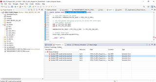
if i closed project & again reopen project then there is no error while building here for your reference, please see video.
If the error went away after closing and re-opening the project with no other changes, something went wrong in the C parser and/or indexer. This is fine- you have nothing to worry about!
Regards,
Jason Osborn
thanks ,
i mereg ADCC SOC4 TempEVAP,for your refernce please see picture as below....facing few issue
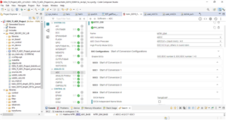
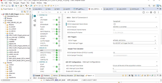
hal.h file...
value1 = (float32_t)(ADC_readPPBResult(PFC_TempEVAP_ADCRES_BASE, PFC_TempEVAP_ADC_PPB_NUM));
while(1)
{
//--------------------------------------Ambient sensor-------------------------------------------------
fTempValue = (float)(ADC_RESOLUTION_VALUE - value1);
fTempValue *= (TEMP_AIR_RES_GND / value1);
Temp_Sensor_Ambient = (float)ntc_sensor_get_temp(fTempValue, TEMP_AIR_RES_T_25, TEMP_AIR_BETA);
}
i have declare Temp_Sensor_Ambient & def function ntc_sensor_get_temp correct.
only issue is ADC value not occur in value1 variable.
please suggest what wrong.
For your reference please see TIDM-02010 reference design.
Hello,
Let's look at your line of code for reading the ADC and analyze what it's actually doing.
So, now let's look at that SysConfig file.
In the ADC section, take a look just below the ADC INT Configurations, and you'll find PPB Configurations. Have you set these values appropriately, to match the ADC base, SOC number, and PPB number you intend to use?
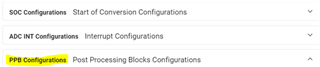
Regards,
Jason Osborn
Unfortunately, I do not know the details of how your project functions, and cannot tell you whether or not this is correctly configured. You need to compare the values assigned to PFC_TempEVAP_ADCRES_BASE and PFC_TempEVAP_ADC_PPB_NUM to the macros created by SysConfig (located in board.h) and ensure they match. Additionally, you need to verify that the SOC number you're assigning to this PPB matches the ADC pin you're trying to sample.
For reference, please see the PPB-related ADC examples provided in Driverlib.
Regards,
Jason Osborn
Dear Jason,
this is original code of tidm-02010 reference design ,in that i have add temperature sensor but here actual reading not occur here
uint32_t* read_ADC_Value=(uint32_t*)0x00000B44;
tempnewvalue1 = (*read_ADC_Value);
fTempValue = (float)(ADC_RESOLUTION_VALUE - tempnewvalue1);//value
fTempValue *= (TEMP_AIR_RES_GND / tempnewvalue1);
Temp_Sensor_Ambient = (float)ntc_sensor_get_temp(fTempValue, TEMP_AIR_RES_T_25, TEMP_AIR_BETA);
here not display value of read ADC value in tempnewvalue1 variable .
please suggested what to do, for your reference please check attachment.
one more 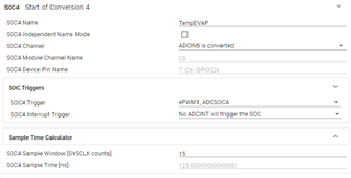
please explain below points:
1.SOC4 trigger: how to select ePWM1,ADCSOCA what logic ? for can i used ePWM2,ADCSOCB
2.SOC4 Sample Window [SYSCLK counts]: 15 .....how was 15 occur ??
ODU_TI_Project_ADC_22122023.zip
i know your are not check customer code but don't worry this is your code ,so kindly check.
Hello,
Based on your questions, I suggest taking a look through the device TRM for the TMS320F280013x, specifically section 11.3 SOC Principle of Operation for ADC SOC configuration.
As I stated above, I highly recommend using the driverlib functions for ADC reading, as seen in the Driverlib examples, instead of sampling the address. Additionally, ADC readings have to occur in an ISR with known timing (typically triggered by the relevant ADC conversion itself) to ensure that the reading occurs at a valid time. Otherwise, you may attempt to read the register while it contains invalid data. Refer to 11.12.1 ADC Timing Diagrams of the device TRM.
For your other questions:
Regards,
Jason Osborn
Thank for your Reply.
In TI existing design solution tidm_02010_dmpfc i have only add one adc those are not implemented.
so i can just implement this.
in that Vac,Iac etc. ADCRESULT value occur correctly what i missed?
I read address of ADCC like
uint32_t* read_ADC_Value=(uint32_t*)0x00000B44; & tempnewvalue1 = (*read_ADC_Value); is it correct?
if yes then corresponding value not occurring.
if not then please suggest what should i do ?
Hello,
As I stated above, I highly recommend using the driverlib functions for ADC reading, as seen in the Driverlib ADC examples, instead of sampling the address. Additionally, ADC readings have to occur in an ISR with known timing (typically triggered by the relevant ADC conversion itself or by a different ADC) to ensure that the reading occurs at a valid time. Otherwise, you may attempt to read the register while it contains data that is not yet ready or while the system as a whole is in a transition state. Refer to 11.12.1 ADC Timing Diagrams of the device TRM.
Regards,
Jason Osborn
Dear Jason,
TIDM-02010 reference design in that ...
you have any document of all function's details explanation.
like: HAL_clearDataRAM((void *)loadStart_est_data, (uint16_t)loadSize_est_data);,
halHandle = HAL_init(&hal, sizeof(hal)); & so on.
Can Have all Function details explanation document ??
There is no singular document which covers all functions in the TIDM-02010 reference design. The vast majority of functions are considered to be self-documenting due to the function's naming scheme and/or simplicity, and have no documentation other than the comments in the source code. For example, if you open the source code of HAL_clearDataRAM, you can see that the function only erases the target memory location. Similarly, the source code of HAL_init can be opened to see that the function initializes the HAL object.
Section 3.2 Getting Started Firmware and section 3.5 Migrate Firmware to a New Hardware Board of the TIDM-02010 User's Guide go over the implementation in more detail.
If you're looking at a function that is not covered by these sections, consider the name of the function and read the comments in the source code. In the vast majority of cases, this should be enough to determine their utility.
Regards,
Jason Osborn