This thread has been locked.

If you have a related question, please click the "Ask a related question" button in the top right corner. The newly created question will be automatically linked to this question.

TMS320F2812: DSP FFT Library Functions Right Order to Use

Part Number: TMS320F2812
Other Parts Discussed in Thread: C2000WARE

Hi 
I am using FFT library and results I am getting look fine but I have still some concerns about some points.

Here above the code snippet currently running. 
1. I am still not sure the order of functions is accurate.

2. My input is 16bits filtered ADC Data in Q15 format, before feeding FFT with my ADC data, am shifting the dataset to the Q30 format which causing precision loss significantly.

How should I interpret my FFT result to link with my ADC results back as they needs to be converted to the G values.

Should I use _IQ30sqrt function after calling rfft_calc function ?

void FFT_Compute(RFFT_t * this)
{
    RFFT32* rff = this->RFFT;
    RFFT32_brev(this->Input.ReadyToUseBuff_Q30, &ipcb[0], FFT_SIZE); // Bit reversed
    this->RFFT->win(rff);                      // Q31 format (abs(ipcbsrc)/2^16).^2
    this->RFFT->calc(rff);                   // Compute the FFT
    this->RFFT->split(rff);                    // Post processing to get the correct spectrum
    this->RFFT->mag(rff);                      // Q31 format (abs(ipcbsrc)/2^16).^2
}

  • Ismail,

    1. The order of functions you have is accurate.

    2.Per 5.2.5 of the DSP fixed point library user guide, the input and window coefficients needs to be Q31. So that's what you would need to get your input data set to. I am not sure I understand why shifting from Q15 to Q31 would lead to precision loss. You are adding fractional bits for the intermediate RFFT operation. In the end you will convert back to whatever precision you need.

    I don't understand what "G values" means.

    Thanks,

    Sira

  • Thank for the reply,

    In my Iqmath.h maximum IQ resolutions is IQ30 as I couldn't find IQ31.

    I set TF_QFMAT in sel_q.asm file to Q30. I'd expect that input form would be Q30 not 31.

    G is gravity. 

    My input is accelerometer data varying between [0, 32767].

    They are compatible with Q15 hence, I am using Q15 FIR and IIR functions, later on I am shifting left by 15 to make them Q30 format compatible.

    But, Q15's interval is [-65536, 65535.999...] however, Q30's interval is [-2,1.999999]. 

    If we think about the FFT results, results will be mapped within Q30 format interval and I don't know their engineering unit, is it raw values or decibels etc. ?

    Because my goal is to reinterpret output magnitude array.

    Btw, should I apply sqrrt to the results after magnetidu function called ?

  • Ismail,

    You need to shift left to go from Q15 to Q30, not Right.

    Square root has already been applied to get to Magnitude. Magnitude values are raw values.

    Thanks,

    Sira

  • Yes, I wanted to say shifting left not right, sorry.

    I fixed the entry.


    As we say raw values, let me verify if we are in the same page.

    Let's say I am feeding FFT with ideal sine-wave which its amplitude value is 32 (uint16) at fixed frequency.

    The reason I am saying 32 is because it is almost equal to 1g according to my conversion table.

    Does FFT suppose to show a peak reaching up to 32 in the amplitude axis at that fixed frequency?

    Or can't we say so as the different mathematical calculations has been applied to the input ?

    Because now I am getting higher int32 values at the output. 

    What I did to correlate FFT outputs with input signal behavior was making an wide-range g values list like
    1g
    2g
    3g
    ...
    1023g ( top limit) and check what FFT output give me at the output and map those outputs with the G values in the table.

    Then I aligned a parabolic function with the table above and inserted that function into the firmware.
    Accuracy wasn't best and that's why I am asking you if there is a point I am missing

  • Ismail,

    If you look at the example in C2000Ware v5.01.00, it is using a sinusoidal input and the comments explain where in the output you can expect a peak.

    Thanks,

    Sira

  • Hi Sira,

        //Simulated input signal
        for(i=0; i < FFT_SIZE; i++){
          ipcbsrc[i]  = (long)(2147483648*(sin(Rad) + cos(Rad*2.3567))/2);  //Q31
          Rad         = Rad + RadStep;
        }
    
    
        RFFT32_brev(ipcbsrc, ipcb, FFT_SIZE); // real FFT bit reversing
        
        rfft.ipcbptr = ipcb;                  // FFT computation buffer  
        rfft.magptr  = ipcbsrc;               // Magnitude output buffer 
        rfft.winptr  = (long *)win;           // Window coefficient array
        rfft.init(&rfft);                     // Twiddle factor pointer initialization
                                              
        rfft.calc(&rfft);                     // Compute the FFT
        rfft.split(&rfft);                    // Post processing to get the correct spectrum                                      
        rfft.mag(&rfft);                      // Q31 format (abs(ipcbsrc)/2^16).^2
            
        //asm("   ESTOP0");
        for(;;);

    This is the example in V1.20.00.00.

    I am afraid, I couldn't get it ..

  • Ismail,

    Please download C2000Ware v5.01.00 (the current version), which contains v1.27.00.00 of the Fixed Point DSP library.

    Thanks,

    Sira

  • I downloaded but still can't understand what I am going to do.

    Let me clarify my case.

    My FFT input is my filtered ADC data which is output of FIR16 hence, my outputs will be in Q15 format.
    RFFT32 says ipcbptr requires the inputs in Q31 format.

     int32_t fft_input  = (int32_t)hpfOutput << 15; //16

    Q1. Fixed DSP documentary say we can either pick Q30 or Q31. I have checked my IQmathlib.h and seen Q30 as highest supported one ( look below  #define table ).

    Should I shift left by 15 or by 16 ? I have set up Q30 in tf_selq.asm file btw.

    #define   QG          GLOBAL_Q
    #define   Q30         30
    #define   Q29         29
    #define   Q28         28
    #define   Q27         27
    #define   Q26         26
    #define   Q25         25
    #define   Q24         24
    #define   Q23         23
    ....
    ....

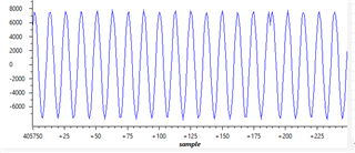
    Q2. For instance, this sine wave is my FIR filter output. This signal is running at 200Hz, highest peak is about the 8000 ADC Raw Value. 

    I know that 8000 ADC Value (we can say 8000 roughly) is equal to 200g roughly. On the other hand, I see peakmag  ~959087 in case shifted by 15, if I shift by 16 then it is equal to ~3841694 which is ~4 times higher value.

    In the example codes, it says

      rfft.mag(&rfft);                      // Q31 format (abs(ipcbsrc)/2^16).^2, 

    If this is the equation that will help to take me my peak ADC Value then how does it calculate ?

        RFFT32_brev(ipcb, ipcb, FFT_SIZE); // real FFT bit reversing
        
        rfft.ipcbptr = ipcb;                  // FFT computation buffer  
        rfft.magptr  = ipcbsrc;               // Magnitude output buffer 
        rfft.winptr  = (int32_t *)win;           // Window coefficient array
        rfft.init(&rfft);                     // Twiddle factor pointer initialization
                                              
        rfft.calc(&rfft);                     // Compute the FFT
        rfft.split(&rfft);                    // Post processing to get the correct spectrum                                      
        rfft.mag(&rfft);                      // Q31 format (abs(ipcbsrc)/2^16).^2

  • Let me check on your questions, specifically the IQMath lib Q, and the magnitude, and get back to you.

  • Thanks for your interest.

  • Ismail,

    The mag generated by the DSP library is the squared of the complex magnitude. Maybe you need to take the square root to get a number that matches the expected value.

    Regarding support for Q31 in IQMath.lib, I'm still checking on it.

    Thanks,

    Sira

  • Ismail,

    You should be able to use Q30 or Q31 for the DSP calculation.

    Thanks,

    Sira