This thread has been locked.

If you have a related question, please click the "Ask a related question" button in the top right corner. The newly created question will be automatically linked to this question.

TMS320F28384D: Brining custom C2000 controller online for the first time.

Part Number: TMS320F28384D

Hello,

so. I have a pretty complex question. I know that it will be hard to answer without physically seeing my hardware setup that I have in front of me, so i will try and provide some schematic screenshots and describe what I am trying to do, and THEN I will describe what is going wrong, and THEN i will ask my question. Please follow along and reach back out with questions. I am in DESPRITE need of help.

1) WHAT I AM TRYING TO DO

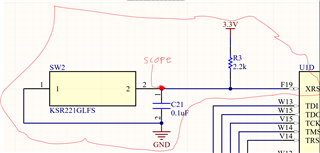
-I recently embedded my own custom C2000 TMS320F28384D controller myself, following the same design principles from the launchpad PCBs, i have followed the datasheet to a T about capacitors, voltage levels, resistors, etc. Essentially my board is a totally empty breakout for the processor. I broke out almost all of the pins, verified them a ton of times etc. My specific package for the processor is the BGA with like 337 pins about?. Below, i have attached my schematic. Under my schematic I will tell you the steps I have taken from the schematic design until now, where the board is on my desk. 

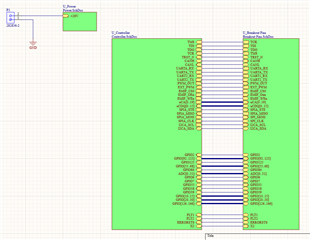
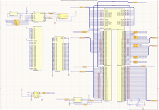
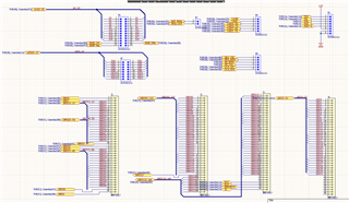
      I will also attach the design as the altium sch and brd files for your reference.F28384DZWTSR_testBoard -simplier.zip

-okay so, since creating these design files i have done the following.

-manufactured and built the board via Macrofab. I did not do any soldering myself, i am confident the BGA is on there correctly. They did electrical testing, so i think electrically speaking, the circuit is in good shape.

-Checked for shorts manually with a DMM, it all looks good. 

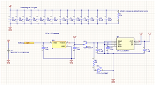
-made sure that the power converters were working. I am successfully getting the 3.3V and 1.2V nets just like the datasheet needs.

-Connected up power, and turned on the power switch, power LED lit up as expected.

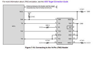
-wired up a XDS110 debug probe to the jtag header, i had to go through a breadboard to do so because I accidentally broke the jtag stuff out in a line and not in two rows as is the 14 pin header of the XDS programmer. 

-verified this circuit works by touching the TDO and TDI lines in a loop NOT connected to my board, and running a "test connection" in CCS. The programmer is working when it just loops back to itself. 

2) WHATS GOING WRONG:

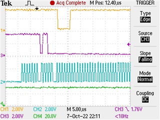
-Whenever I connect in my jtag TDO and TDI lines to TDO and TDI respectively, (i am following the TMS320's datasheet on how to connect a 14 pin jtag programmer), the JTAG test connection fails, and i get this message:

The value is '-233' (0xffffff17).
The title is 'SC_ERR_PATH_BROKEN'.

The explanation is:
The JTAG IR and DR scan-paths cannot circulate bits, they may be broken.
An attempt to scan the JTAG scan-path has failed.
The target's JTAG scan-path appears to be broken
with a stuck-at-ones or stuck-at-zero fault.

-I get the SAME error if i just leave TDO and TDI unconnected from the XDS110. This tells me the processor is not booting up to where it should be for some reason. I have never brought a C2000 processor online for the firs time besides on a launchpad, so i don't really know how to get the device to boot up right. I know other controllers like STM32s have a boot0 pin you have to tie low the first time you program, but i am not able to find something like this in the datasheet. 

3) MY QUESTIN:

- Basically, my question amounts to this: What is the correct order of steps for first time programming on a c2000 chip? If I need to add switches to my circuit i can! I have broken out about EVERY pin from the BGA, so i WILL be able to make circuit changes if needed. Please help me figure this out. I have included photos of the schmeatic, and if those are not enough, I also zipped up my whole altium project and attached it. I can provide any further photos of anything if needed. I really need to know how to program this chip for the first time. 

-Oh ALSO, I made a new CCS project for this thing, and specifically selected it as the target. Made it an empty main.c program, and then added a config file to select the XDS110 probe as the programmer. The step I am stuck on is clicking "test connection" in the .ccxml config file. Oh and here is a screenshot of my JTAG setup on CCS.

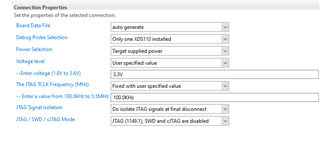
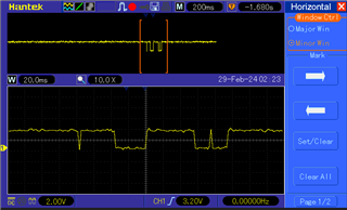
-I have tried adjusting the JTAG TCLK frequency to a lot of values between 100Khz and 20 MHz, and that change dose not make a difference to my test results. I am very confident I am just missing something hardware wise in getting the processor to boot up correctly the first time. 

If this would require a video or auido call to help me, I am happy to zoom or whatever is best. Just send me a email at silas.perry@whisperaero.com.

thanks!!!!

  • Hi,

    If you have access to an oscilloscope, could you try probing TDO (yellow), TMS (purple), TCK (blue), and TRST (green) as shown below. The screenshot below was captured using the XDS100, and it was a single-capture triggered on the falling edge of TMS. Could you try doing the same and see if your probed signals look the same? I'm assuming from your error message that you won't see anything on TDO, but I want to make sure.

    What do you see on the XRSn pin when the device is powered on? On an unprogrammed device, you should be seeing a reset every ~50ms due to the watchdog.

    Your JTAG circuit looks correct in the schematic, and there are no special steps for first time programming. I would be curious to see scope captures on the power rails to make sure the voltages look good.

    Best Regards,

    Ben Collier

  • Hello Ben. 

    Thanks for your reply. After reading your message, i decided a good first scope measurement to take would be the power ground rails as well as the XRSn pin. I have attached the following below. First is the 3.3v net, next is the 1.2V net, and third is the XRSn pin. 

    I am nervous about what I am seeing on the XRSn pin. Instead of the pulses you described, it looks like it is just getting tied high to 3.3V all the time. So the forth image is my circuitry for that specific pin, which is also viewable in the above screenshots but i included it here to highlight and zoom in on it. 

    Does it look like i connected the XRSn pin wrong in my schematic? it is tied to 3.3V through a resistor as seen in the 4th figure below. Please see below. 


    figure 1 - 3.3v net measured on power rail

    figure 2 - 1.2V net measured on power rail

    Figure 3 - XRSn pin measured at point indicated in figure 4

    figure 4 - XRSn circuit, also shows where scope was to measure. 

    Please get back to me as soon as possible, I apricate your time. 

    thanks,

    -Silas Perry

  • Hi,

    Could you try replacing R3 with a 10K resistor? I believe the resetting is only normal in most of our devices, so that may not be an issue, I will need to check.

    Also, could you try scoping TDO while testing connection? I want to see if there is any output from the device.

    Best Regards,

    Ben Collier

  • hello. 

    Yes i can try replacing R3 with any value. Below is a scope shot of TDO when the probe is plugged into my board, during a "test connection" from CCS.

    I have NOT replaced the resistor yet, but i will do so now. 

    Here is the screenshot:

  • Here is another screenshot of all JTAG lines on logic analyzer, before i change the resistor value of R3

  • again before I change R3 i logic analyzed the XRSn pin, and i am getting the following waveforms. the second one is a zoom in on the falling edge of each pulse. I don't really know what I am seeing here. 

    The width of each pule is 40us, and the width between each pulse is 2.38ms. 

  • Hello one last time. 

    I did not have a 10k, but I actually had the wrong resistor value there at the first try. I changed it to be 2.2k like it should have been. I am now seeing the following waveform when trying to test: 

  • THis might also help.

    When i completely unplug the probe from the circuit, the following can be seen on the logic analyzer. 

  • Hi,

    hello. 

    Yes i can try replacing R3 with any value. Below is a scope shot of TDO when the probe is plugged into my board, during a "test connection" from CCS.

    I have NOT replaced the resistor yet, but i will do so now. 

    Here is the screenshot:

    Ok, so you are seeing some activity on TDO in this oscilloscope capture? 

    Here is another screenshot of all JTAG lines on logic analyzer, before i change the resistor value of R3

    But you do not see any activity on TDO when using a logic analyzer? Nothing has been changed since the oscilloscope capture? 

    again before I change R3 i logic analyzed the XRSn pin, and i am getting the following waveforms. the second one is a zoom in on the falling edge of each pulse. I don't really know what I am seeing here. 

    The width of each pule is 40us, and the width between each pulse is 2.38ms. 

    Ok, so now you are seeing the pulsing behavior on XRSn? This is expected, and means that the device is powered and operating as expected.

    THis might also help.

    When i completely unplug the probe from the circuit, the following can be seen on the logic analyzer. 

    This is expected due to TMS, TCK, TDI, TDO internal pullups and TRST internal pulldown. 

    What resistor value was there for R3? If you test connection, do you still see the same error and no activity on TDO with your current setup?

    Best Regards,

    Ben Collier 

  • Hello Ben, 

    I will answer your questions sequentially and number them. 

    1) I was seeing a tiny bit of activity on the scope during one of my tests, but the jtag probe still said it could not circulate bits during that test.

    2) On the logic analyzer I have never seen any activity on TDO that is correct. I may have changed something between those two tests I am not sure. 

    3)I am seeing pulsing on the XRSn pin yes. It is no longer in 40ms chunks, its a bit longer but yes I am seeing it. 

    4)The resistor value for R3 is 2.2k ohms currently, and I do not currently have the means to change it. No i still do not see any activity with the probe in the circuit. If i place the probe in the circuit, the TDO line goes completely un responsive.

    Since the device did power on as expected according to the pulses, could this simply be an issue with the debug probe somehow? 

    Please help me think of some ideas for fixing this. 

    thanks!

    -Silas Perry

  • Silas,

    It's possible that the debug probe is the issue, but I would be somewhat skeptical since you said it passed the connection test when you looped back the signal to itself.

    I am somewhat curious about what your JTAG header looks like on your board. In the schematic, it is shown as a 8-pin connector. How are the signals connected between this JTAG header to your JTAG debug probe? I wonder if there has been some mistake here. 

    Best Regards,

    Ben Collier

  • Hello, I have followed the following circuit exactly. 

    The 8 pin header has the pins on the left side exposed, and i am using the 20-14 pin connector of the debug probe to jump the wires from that over to a breadboard where they meet the wires of the controller from that 8 pin header. 

    I have lowered the clock on jtag to only 100kHz, so there should be no issue with using the breadboard as an intermediate between the processor and the debug probe. I have double and triple checked the connections so many times on teh breadboard between the probe and processor, i know it is correct to the above picture. 

    Again, the point where the processor stops its pulses is when i plug the power and ground lines in from the 8 pin header to the breadboard so the probe is connected and able to sense  the power rail of the controller. 

  • Hi,

    Again, the point where the processor stops its pulses is when i plug the power and ground lines in from the 8 pin header to the breadboard so the probe is connected and able to sense  the power rail of the controller. 

    I must have missed this before. The XRSn pulsing stops when you connect the power and ground to your JTAG probe? Could you disconnect TRSTn and see if that behavior is the same? 

    I do not think this is expected behavior, so let's focus on this.

  • Is it specifically the VTREF connection that causes the stop in the pulsing? I want to figure out which connection specifically is the last one made that will stop the XRSn from pulsing.

    Best Regards,

    Ben Collier

  • hello Ben, 

    I have an update that might help you. So i realized i have had TMS and TCK switched. So I swapped them and now i am getting the below message instead. 

    As for which connection specifically was breaking the XRSn pin from fluctuating, it happened any time I plugged one of the probes lines into 3.3V or GND, it did not matter which probe pin or which side of the power rail. 

    However since i am now seeing some life at least, maybe you can help me just tune this performace?

    [Start: Texas Instruments XDS110 USB Debug Probe_0]

    Execute the command:

    %ccs_base%/common/uscif/dbgjtag -f %boarddatafile% -rv -o -S integrity

    [Result]


    -----[Print the board config pathname(s)]------------------------------------

    C:\Users\sperry\AppData\Local\TEXASI~1\CCS\
    ccs1260\0\0\BrdDat\testBoard.dat

    -----[Print the reset-command software log-file]-----------------------------

    This utility has selected a 100/110/510 class product.
    This utility will load the adapter 'jioxds110.dll'.
    The library build date was 'Dec 6 2023'.
    The library build time was '17:33:10'.
    The library package version is '12.6.0.00029'.
    The library component version is '35.35.0.0'.
    The controller does not use a programmable FPGA.
    The controller has a version number of '5' (0x00000005).
    The controller has an insertion length of '0' (0x00000000).
    This utility will attempt to reset the controller.
    This utility has successfully reset the controller.

    -----[Print the reset-command hardware log-file]-----------------------------

    The scan-path will be reset by toggling the JTAG TRST signal.
    The controller is the XDS110 with USB interface.
    The link from controller to target is direct (without cable).
    The software is configured for XDS110 features.
    The controller cannot monitor the value on the EMU[0] pin.
    The controller cannot monitor the value on the EMU[1] pin.
    The controller cannot control the timing on output pins.
    The controller cannot control the timing on input pins.
    The scan-path link-delay has been set to exactly '0' (0x0000).

    -----[Perform the Integrity scan-test on the JTAG IR]------------------------

    This test will use blocks of 64 32-bit words.
    This test will be applied just once.

    Do a test using 0xFFFFFFFF.
    Scan tests: 1, skipped: 0, failed: 0
    Do a test using 0x00000000.
    Scan tests: 2, skipped: 0, failed: 0
    Do a test using 0xFE03E0E2.
    Test 3 Word 0: scanned out 0xFE03E0E2 and scanned in 0xFFFFFFFF.
    Test 3 Word 1: scanned out 0xFE03E0E2 and scanned in 0xFFFFFFFF.
    Test 3 Word 2: scanned out 0xFE03E0E2 and scanned in 0xFFFFFFFF.
    Test 3 Word 3: scanned out 0xFE03E0E2 and scanned in 0xFFFFFFFF.
    Test 3 Word 4: scanned out 0xFE03E0E2 and scanned in 0xFFFFFFFF.
    Test 3 Word 5: scanned out 0xFE03E0E2 and scanned in 0xFFFFFFFF.
    Test 3 Word 6: scanned out 0xFE03E0E2 and scanned in 0xFFFFFFFF.
    Test 3 Word 7: scanned out 0xFE03E0E2 and scanned in 0xFFFFFFFF.
    The details of the first 8 errors have been provided.
    The utility will now report only the count of failed tests.
    Scan tests: 3, skipped: 0, failed: 1
    Do a test using 0x01FC1F1D.
    Scan tests: 4, skipped: 0, failed: 2
    Do a test using 0x5533CCAA.
    Scan tests: 5, skipped: 0, failed: 3
    Do a test using 0xAACC3355.
    Scan tests: 6, skipped: 0, failed: 4
    Some of the values were corrupted - 65.6 percent.

    The JTAG IR Integrity scan-test has failed.

    -----[Perform the Integrity scan-test on the JTAG DR]------------------------

    This test will use blocks of 64 32-bit words.
    This test will be applied just once.

    Do a test using 0xFFFFFFFF.
    Scan tests: 1, skipped: 0, failed: 0
    Do a test using 0x00000000.
    Scan tests: 2, skipped: 0, failed: 0
    Do a test using 0xFE03E0E2.
    Test 3 Word 0: scanned out 0xFE03E0E2 and scanned in 0xFFFFFFFF.
    Test 3 Word 1: scanned out 0xFE03E0E2 and scanned in 0xFFFFFFFF.
    Test 3 Word 2: scanned out 0xFE03E0E2 and scanned in 0xFFFFFFFF.
    Test 3 Word 3: scanned out 0xFE03E0E2 and scanned in 0xFFFFFFFF.
    Test 3 Word 4: scanned out 0xFE03E0E2 and scanned in 0xFFFFFFFF.
    Test 3 Word 5: scanned out 0xFE03E0E2 and scanned in 0xFFFFFFFF.
    Test 3 Word 6: scanned out 0xFE03E0E2 and scanned in 0xFFFFFFFF.
    Test 3 Word 7: scanned out 0xFE03E0E2 and scanned in 0xFFFFFFFF.
    The details of the first 8 errors have been provided.
    The utility will now report only the count of failed tests.
    Scan tests: 3, skipped: 0, failed: 1
    Do a test using 0x01FC1F1D.
    Scan tests: 4, skipped: 0, failed: 2
    Do a test using 0x5533CCAA.
    Scan tests: 5, skipped: 0, failed: 3
    Do a test using 0xAACC3355.
    Scan tests: 6, skipped: 0, failed: 4
    Some of the values were corrupted - 65.6 percent.

    The JTAG DR Integrity scan-test has failed.

    [End: Texas Instruments XDS110 USB Debug Probe_0]

  • Silas,

    I am really sorry about the delay, but I will need a day or two to get back to you. 

    Best Regards,

    Ben Collier

  • Hello Ben, 

    I was able to figure out the problem. There were a number of issues. First, the resistor value of R3 was at only 56 ohms, so the boardhouse screwed up that i had it manufactured at. I replaced it with a 2.2k resistor. Secondly, i accidentally messed up the silkscreen on my board so TMS and TCK labels were switched. Once i switched those wires things got easier. Next, I also have to put the device into the "wait boot" mode by pulling GPIO 72 high and GPIO 84 low. Thirdly, I could not have my logic analyzer connected at all to the circuit. Once I took out the logic analyzer the board was able to wake up and work as expected. I now have an LED blink program running on it. 

  • Glad you issue has been resolved!