This thread has been locked.

If you have a related question, please click the "Ask a related question" button in the top right corner. The newly created question will be automatically linked to this question.

TMS320F28P650DK: Buck Regulator Control with C2000 at 3MHz Switching Frequency

Part Number: TMS320F28P650DK
Other Parts Discussed in Thread: TIDM-DC-DC-BUCK, PMP41081

Hi,

I'm trying to control a 3MHz buck regulator. What are the limitations I can come across at this switching frequency?

The goal it to use peak current mode control and a goal crossover frequency of about 300kHz.

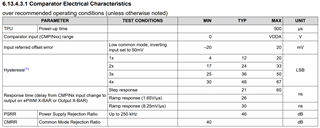
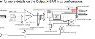
For the current feedback, I was thinking of using a high speed comparator to send a flag to the MCU when the inductor current hits the voltage control threshold. This is because the sample rate is 3.92 MSPS, which is not fast enough to track the inductor ripple. Do you see this being achievable?

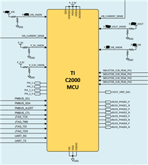
Can the C2000 accept an interrupt for the current loop and still maintain control?

What other control schemes have you used other than peak current mode control? Is there a control scheme that highlights the 2000 better than others?

What are some other recommendations you may have that could achieve this?

  • Hi Mike,

    At switching frequencies above 300-500 kHz, you will need to leverage our HRPWM module which offers duty control at up to 150ps resolution. This will give enough resolution to realize the control effort from Digital control library compensator. Do you currently know what your requirement for control loop frequency is?

    For this high speed comparator, are you referring to an external component - do you have part number for this device? We have internal CMPSS in our C2000 device, have you reviewed the specifications for that module? We can support receiving an external signal to shut off the EPWMs on a cycle-by-cycle basis, that doesn't look to be an issue. Our reference designs all leverage the internal CMPSS for PCMC and it will be easier to adjust the CMPSS DAC threshold in your control loop as you needn't worry about synchronization. We don't have reference for using external high comparator but can support the configuration for it in our EPWM module, whether this be as a trip signal or external interrupt signal.

    I think peak current mode control should be sufficient to achieve this control and we have a reference design which directly showcases PCMC for buck converter control. See TIDM-DC-DC-BUCK, which also shows voltage mode control for this application. It's also possible to use average current mode control but PCMC will be better than VMC and ACMC for transients and overall control.

    Regards,

    Peter

  • Hi Peter,

    Yes, I plan on using the HRPWM. The control loop frequency I'm targeting is about 300kHz. Do you know if anyone has achieved loop control, at 3MHz switching frequency, with the C2000?

    For the high-speed comparator, no, I haven't picked a component yet. If the CMPSS is capable, I won't need it.

    When you say, "We can support receiving an external signal to shut off the EPWMs on a cycle-by-cycle basis, that doesn't look to be an issue.", do you know if the CMPSS can handle cycle-by-cycle at 3MHz?

    The goal is to also have a total of 4 phases as well. Do you know if your team has any references or has any experience utilizing multiphase buck control for the C2000?

  • Hi Mike,

    We've experimented with running 2 MHz switching frequency for LLC topology using our 120 MHz devices. It should be feasible to run at 3 MHz considering F28P65x device is 200 MHz CPU, though we don't have any reference designs showing 3 MHz Fsw operation yet. Are you targeting to use dual-core F28P65x or single-core F28P65x? The C2000 device can run the C28x and CLA cores concurrently, so you can offset control loop to CLA, and to dual-core C28x if utilizing the dual-core package. 

    For external high-speed comparator, you can leverage the comparator output signal as an input directly to the EPWM Digital Compare module (through the EPWM XBAR). When configured, the EPWM will trip its output when the input signal is high on a cycle-by-cycle basis. I assume you will need to leverage our C2000 DAC module to adjust the trip threshold for an external comparator, which would add design complexity to your board.

    The CMPSS that is internal to the C2000 device is asynchronous to the device clock, so the propagation time from CMPx input to tripping EPWM is minimized. Since CMPSS is asynchronous, signal chain from CTRIP output to the EPWM digital compare module is more important. If you leverage the Trip Zone module, this signal chain is asynchronous to the device clock, as well. See below timings specced in our datasheet

    Regarding multiphase buck converter, as far as I know, we have only released designs with single phase buck. There is some development with multiphase buck topology but it's currently unreleased. From a device peripheral perspective, have you outline the total number of PWM, ADC, CMPSS, GPIO pins required for system?

    Regards,

    Peter

  • Hi Peter,

    That's good to know! Just curious about the LLC, is it a full-bridge or half-bridge on the primary side?

    Yes, I'm targeting the dual-core package. I definitely plan on utilizing both cores. It's great to know that the cores can run concurrently.

    When you say that the CMPSS is asynchronous with the system clock, what exactly does that mean? Are you saying that the CMPSS signals are not dependent on the system clock? 

    Any insight/lessons-learned that your team is willing to share regarding your experience thus far with the multiphase buck would be greatly appreciated.

    Yes, if I go with the external comparator approach, it's looking like the following:

    • PWM - 12 complimentary pairs
    • ADC - 7 single-ended inputs
    • GPIO - 14 signals
    • DAC - 1 signal

    If I utilize the CMPSS, it would look like the following:

    • PWM - 12 complimentary pairs
    • ADC - 7 single-ended inputs
    • GPIO - 10 signals
    • CMPSS - 4 signals

    Below is a snippet of my block diagram for the converter I'm designing, with a few things redacted being that this is a public forum. The converter is actually separated into two stages. In stage 1, VIN is stepped down to an intermediate bus voltage (VIB), and in stage 2, VIB is stepped down to VOUT.

  • How can I ensure that this MCU can work for this converter solution?

  • Hi Mike,

    Just curious about the LLC, is it a full-bridge or half-bridge on the primary side?

    LLC in question is a spin of PMP41081, which is a half-bridge LLC design. 

    When you say that the CMPSS is asynchronous with the system clock, what exactly does that mean? Are you saying that the CMPSS signals are not dependent on the system clock? 

    Please see below subsection of the CMPSS block diagram. The output of the internal comparator (COMPH/COMPL) within the CMPSS module has an asynchronous output when going to the XBARs of the device. We also support synced, filtered, and latched CMPSS output depending on the application, but ASYNCH will give the least time delay.

    Any insight/lessons-learned that your team is willing to share regarding your experience thus far with the multiphase buck would be greatly appreciated.

    Unfortunately we haven't expanded to multiphase support but that is scoped. From an implementation perspective, once single phase operation works sufficiently well, adding additional phases can reuse a lot of the existing module configuration implementation from the single phase implementation, and the phase-shift capabilities of the EPWM module and synchronization scheme can then be leveraged to add the 90deg offsets for the additional phases.

    How can I ensure that this MCU can work for this converter solution?

    Given the pin requirements you described, the F28P65x can sufficiently support that. And since you are looking at the dual-core variant of this device, the control requirements should be sufficient. We don't have any reference designs for applications running at 3MHz Fsw, that is the only area where it would be necessary to do testing first

    Have you worked with an evaluation module for this device yet? Would recommend leveraging the controlCARD interface for initial testing and prototyping