This thread has been locked.
If you have a related question, please click the "Ask a related question" button in the top right corner. The newly created question will be automatically linked to this question.
Hello everyone,
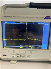
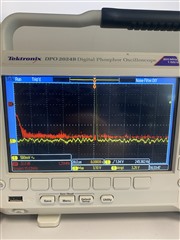
I need to obtain a radiation spectrometer using the ADC of the C2000 launchpad. The ADC configuration has been set to sample at the fastest rate possible. I confirmed from the oscilloscope that I can sample at intervals of 600 ns when controlled with the ISR. The signal from a CZT-type semiconductor detector is amplified with a Cremat preamplifier. The signal output seen on the oscilloscope varies between 300-600 mV depending on the radiation source. The rise time of the signal at the preamplifier output is approximately 2 microseconds. I believe that sampling at 600 ns intervals should be sufficient. I'm sure the ADC is working correctly because I can sample sine and square waves at 1 MHz from a signal generator and capture the peak points. However, for some reason, when I connect the preamplifier output to the ADC input, I can read zero or near-zero values. Could this be due to impedance mismatch? If not, what recommendations do you suggest for troubleshooting? The code attached below.
#include "F28x_Project.h" // Cihaz Başlık Dosyası ve Örnekler Dahil Dosyası #define DATA_SIZE 128 float input_data[DATA_SIZE] = {0}; // ADC'den gelen veri dizisi float filtered_data[DATA_SIZE] = {0}; // Filtrelenmiş veri dizisi float Result = 0; float peak_value; // ADC verilerini okuyan ve filtreleyen fonksiyon void ReadAndFilterADCData() { int i; // ADC'den veri oku ve input_data dizisine kaydet for(i = 0; i < DATA_SIZE; i++) { input_data[i] = AdcaResultRegs.ADCRESULT0; // Örneğin AdcaResultRegs.ADCRESULT0, ADC'nin sonuç kaydı // Bu, gerçek donanımınıza göre değişebilir } // Trapezoidal filtreleme işlemi for(i = 0; i < DATA_SIZE; i++) { // İlk iki ve son iki örneği doğrudan kopyala if(i < 2 || i >= DATA_SIZE - 2) { filtered_data[i] = input_data[i]; } else { // Trapezoidal filtreleme filtered_data[i] = (input_data[i - 2] + 2 * input_data[i - 1] + 2 * input_data[i] + 2 * input_data[i + 1] + input_data[i + 2]) / 8.0; } } } // Tepe noktasını bulan fonksiyon float FindPeak(float filtered_data[], int data_size) { float peak_value = filtered_data[0]; // Tepe noktasının başlangıç değeri, dizinin ilk elemanı olarak belirlenir // Tüm diziyi tarayarak tepe noktasını bul int i; for (i = 1; i < data_size; i++) { // Eğer mevcut eleman tepe değerinden büyükse, tepe değeri güncellenir if (filtered_data[i] > peak_value) { peak_value = filtered_data[i]; } } // Bulunan tepe değeri döndürülür return peak_value; } interrupt void adcint1_isr(void) { Result = AdcaResultRegs.ADCRESULT0; //GpioDataRegs.GPBTOGGLE.bit.GPIO32 = 1; PieCtrlRegs.PIEACK.all = PIEACK_GROUP1; // Kesme bayrağını temizle } void main(void) { // Sistem Kontrolünü Başlat: // PLL, WatchDog, Periferik Saatleri etkinleştir InitSysCtrl(); // Tüm kesmeleri temizleyin ve PIE vektör tablosunu başlatın: // CPU kesmelerini devre dışı bırak DINT; // PIE kontrol kayıtlarını varsayılan durumlarına başlatın. // Varsayılan durum, tüm PIE kesmelerinin devre dışı bırakılması ve bayrakların temizlenmesidir. InitPieCtrl(); // CPU kesmelerini devre dışı bırakın ve tüm CPU kesme bayraklarını temizleyin: IER = 0x0000; IFR = 0x0000; // PIE vektör tablosunu kabuk Kesme Servis Rutinlerine (ISR) işaretçilerle başlatın. // Bu, kesme kullanılmıyor olsa bile tüm tabloyu doldurur. // Bu, hata ayıklama amaçları için yararlıdır. // Kabuk ISR rutinleri, F2837xD_DefaultIsr.c dosyasında bulunur. InitPieVectTable(); // Global Kesmeleri ve daha yüksek öncelikli gerçek zamanlı hata ayıklama olaylarını etkinleştirin: //EINT; // Global kesmeyi etkinleştir INTM //ERTM; // Global gerçek zamanlı kesmeyi etkinleştir DBGM EALLOW; // GPIO34'ü Başlat: GpioCtrlRegs.GPBGMUX1.bit.GPIO32 = 0; GpioCtrlRegs.GPBMUX1.bit.GPIO32 = 0; // Pini GPIO olarak yapılandır GpioCtrlRegs.GPBDIR.bit.GPIO32 = 1; // GPIO34'ü çıkış olarak tanımla GpioDataRegs.GPBDAT.bit.GPIO32 = 1; // Çıkış kilitlenmesine 1 girin // Timer0 kesmesi için dönem değerini yükle CpuTimer0Regs.PRD.all = 30 - 1; // Varsayılan 2000 CpuTimer0Regs.TPR.bit.TDDR = 0; // Zamanlayıcı için öncül değeri 1 olarak ayarla CpuTimer0Regs.TCR.bit.TSS = 1; // Zamanlayıcıyı durdur CpuTimer0Regs.TCR.bit.TRB = 1; // Zamanlayıcıyı yeniden yükle CpuTimer0Regs.TCR.bit.TIE = 1; // Zamanlayıcı0 kesmesini periferik seviyede etkinleştir CpuTimer0Regs.TCR.bit.TSS = 0; // Zamanlayıcıyı başlat // ADC için ayarları yap AdcaRegs.ADCCTL2.bit.PRESCALE = 6; // ADCCLK bölenini /4 olarak ayarla AdcaRegs.ADCCTL1.bit.ADCPWDNZ = 1; // ADC'yi etkinleştir AdcaRegs.ADCCTL1.bit.INTPULSEPOS = 1; // Kesme darbesi pozisyonlarını geç ayarlara ayarla AdcaRegs.ADCCTL2.bit.RESOLUTION = 0; // 12-bit çözünürlük AdcaRegs.ADCCTL2.bit.SIGNALMODE = 0; // Tek bitişik (sadece 12-bit modu) // ADC kullanmadan önce en az 500 mikrosaniye gecikme olmalı DELAY_US(1000); // ADC'nin dönüştürme yapacağı pini belirle AdcaRegs.ADCSOC0CTL.bit.CHSEL = 1; // SOC0 pini ADCINA0'ı dönüştürecek AdcaRegs.ADCSOC0CTL.bit.ACQPS = 15 - 1; // Örnekleme penceresi 8000 SYSCLK döngüsü AdcaRegs.ADCSOC0CTL.bit.TRIGSEL = 0x01; // CPU Timer 0 ile tetikle // ADCINT1'in EOC0 bayrağını ayarla AdcaRegs.ADCINTSEL1N2.bit.INT1SEL = 0; // EOC0 INT1 bayrağını ayarlar AdcaRegs.ADCINTSEL1N2.bit.INT1CONT = 1; // Kesmeler oluşturulacak AdcaRegs.ADCINTSEL1N2.bit.INT1E = 1; // INT1 bayrağını etkinleştir // ISR adresini yeniden yönlendir: PieVectTable.ADCA1_INT = &adcint1_isr; // PIE bloğunu etkinleştir PieCtrlRegs.PIECTRL.bit.ENPIE = 1; // PIE Grup 1 INT1 ADCA1'i etkinleştir PieCtrlRegs.PIEIER1.bit.INTx1 = 1; // CPU INT1'i etkinleştir (Xint1 dahil) IER |= M_INT1; // Global kesme maskesini etkinleştir (INTM) EINT; // Gerçek zamanlı kesme maskesini etkinleştir (DBGM) ERTM; EDIS; // Ana döngü while(1) { ReadAndFilterADCData(); peak_value = FindPeak(filtered_data, DATA_SIZE); } }
Hi,
The signal output seen on the oscilloscope varies between 300-600 mV depending on the radiation source. The rise time of the signal at the preamplifier output is approximately 2 microseconds. I believe that sampling at 600 ns intervals should be sufficient. I'm sure the ADC is working correctly because I can sample sine and square waves at 1 MHz from a signal generator and capture the peak points.
How are you expecting to sample at the peak? Are you using some sort of peak detection circuit?
Best Regards,
Ben Collier
There is no front electronic (peak detection etc) before ADC input expect to pre-amp I mentioned. Basically, I am using moving average or trapezoida filter to make the signal smoothier and choose a window size to assign ADC outputs to an array so that I can sort and detect the peak of the signal I sampled. Of course, it causes delay and escape of the signal, but its okay in spectrometer because it would only make the time of measurement longer. On the other hand, yesterday I recognized that when the sines/squares by signal generator were set to approximately 20 V, the signal input of ADC was almost 0V. When I increased the amplitude of signal generator up to 23 V, then I was able to see 0-4096 in ADC output. There is a voltage drop or something like that but I have no idea what's going on. Also, I increased the gain of the amplifier so that my detector's signal amplitude was about 50V, but again there was no signal in ADC input. This could be the result of impedance mismatching. Different level of impedance of detector and signal generator could explain it or not. In both cases, I really need to solve this problem.
Thanks,
Halit
Halit,
I am not sure if I understand your system well enough to help with this problem, since it seems like something is going wrong outside of the ADC.
Just curious, is it possible for you to scope the ADC input?
Best Regards,
Ben Collier
Yes Benjamin, I can monitor the ADC input in oscilloscope. No issue at all. However, when it comes to ADC output, I can see nothing. Its similarlay strange to me.
Ok, I am curious to see what you see with an oscilloscope. I can comment further after that.
Sorry for the huge gap, had some paperwork to handle. I have a picture of oscilloscope showing the output of the signal (op-amp output). For the isolation purpose of high impedance in my source, I employed a LF353 op-amp and the picture of oscilloscpe belongs to output of the op-amp (non-inverting unity gain setup). I cross-checked that the input of the op-amp and output is same as I expected. This is the detector side and everything is OK as expected. On the C2000 ADC side, my sampling frequency is about 1.65 Mhz which is almost 600 ns as I already mentioned. When I supply the sine signal up to 1 Mhz to the input of LF353 through signal generator, the output so that the input of ADC is the same and stabil as expected. The different amplitude levels from 0 to 3 V were also tested and it is OK. ADC perfectly worked for sine wave even in high frequencies. The strange thing begins when I connect detector setup to the ADC input. ADC reads continuoulsy zero except for a few very very small signals I can see in the output of ADC. I looked at examples in Charge-Sharing Driving Circuits for C2000 ADCs (using TINA-TI simulation tool) (Rev. A) https://www.ti.com/lit/an/spracv0a/spracv0a.pdf?ts=1711982105174&ref_url=https%253A%252F%252Fe2echina.ti.com%252Fsupport%252Fmachine-translation%252Fmt-c2000-microcontrollers%252Ff%252Fmt-c2000-microcontrollers-forum%252F345666%252Ftms320f28388d-16-adc
In second example, very similar parameters had been chosen so yesterday I decided to test the formulations there in order to calculate RC filter with respect to sampling rate I chose. The bandwidth of RC is about 150 kHz, and 4 times higher bandwidth for op-amp is also OK. According to the formulations, RC parameters was handled as 5 ohm and 220 nF respectively. However, it also didn't work. As a summary of my work:
1) Detector Signal > Preamplifier > Shaper > LF353 (output checked by oscilloscpe here signal is OK) > ADC (zero output except for a few very very small signals)
2) Detector Signal > Preamplifier > Shaper > LF353 > RC low-pass filter (output checked by oscilloscpe here signal is OK) > ADC(zero output except for a few very very small signals)
How are you setting up your ADC SOCs? How are the ADC conversions being triggered?
hen I increased the amplitude of signal generator up to 23 V, then I was able to see 0-4096 in ADC output. There is a voltage drop or something like that but I have no idea what's going on. Also, I increased the gain of the amplifier so that my detector's signal amplitude was about 50V, but again there was no signal in ADC input.
I have to say that this is weird to change nothing but your input signal amplitude, and then you go from seeing full scale ADC range to seeing nothing.