This thread has been locked.

If you have a related question, please click the "Ask a related question" button in the top right corner. The newly created question will be automatically linked to this question.

TMS320F2800157:Motor control SDK generic project's voltage sampling anomaly

Part Number: TMS320F2800157
Other Parts Discussed in Thread: DRV8300, LAUNCHXL-F280025C

产品编号:TMS320F2800157

Hi,I encountered the following issues in my incremental build project.I hope you can answer it for me

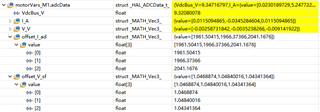
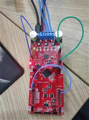
Q1:I built the project in increments from the Motor Control SDK Generic Project and Lab User Guide (spruj26 filename). Now there is a problem with voltage sampling, the voltage offset coefficient is usually around 0.5, while the value of I is greater than 1 (as shown in Figure p1). Launchpadf2800157 Follow the user guide in Figure p2 to connect drv8323rh, connect the 47nF capacitor to C9, C10, and C11, and do the following according to the relevant questions in the forum:

   For S2, place (1) the SEL1 (left) switch up, connect GPIO28 and GPIO29 to the BoosterPack connector, then place (1) the SEL2 (right) switch up, GPIO16 and GPIO17 are then output to the virtual COM at the XDS110 debugger port.
   For S3, the SEL1 (left) switch is pulled down to pull GPIO24 to logic 0, and the SEL2 (right) switch is pulled up to pull GPIO32 to logic 1 to put the F280025C in wait-to-start mode, reducing the risk of connection issues or previously loaded code execution.
   For S4, if the predefined symbol "CMD_CAN_EN" is set in the project properties, and S4 is set to off (on), GPIO32 and GPIO33 will be routed to the CAN transceiver and the J14 CAN interface
For S5, SEL1 (left) switch is placed down to GPIO44/37/43 routing eQEP1 at encoder interface on J12, and SEL2 (right) switch is placed down to GPIO14/25/2/26 routing eQEP2 at Hall sensor interface on J13.
I used the case of f280015x and drv8323rs. Did it make a difference? If it doesn't work, what's the cause of the problem? How can I fix this?

Q2:In the official case of f280015x motor driver, is Flash_lib_HVKIT_3SC compatible with drv8300? If not, which model is appropriate?

Q3:In the official case, external crystals are used by default. Where can I modify it to use internal crystals?

Thank you for any help!

  • Hello,

    If you are using the DRV8323rs, can you try and change the build configuration of your project to be "Flash_lib_DRV8323RS_3SC"? To use the internal crystals of the F280015x, comment out line 145 (#define USE_PLL_SRC_XTAL) and uncomment line 146 (#define USE_PLL_SRC_INTOSC).

    Kind regards,

    Skyler

  • Thanks,Skyler!

    In the official case of f280015x, there are only Flash_lib_DRV8323RS_3SC and Flash_lib_HVKIT_3SC. I am using Flash_lib_DRV8323RS_3SC, but my BoosterPack is DRV8323RH.

    I saw that other posts can solve the voltage sampling bias problem by installing a 47nF capacitor, but I have obviously installed a 47nF capacitor, so I don't know how to solve it at present. I added a 47nF 16V capacitor, so I connected an external 10V voltage source. My voltage sampling values seem fine, except that the voltage offset factor is greater than 1 instead of the normal 0.5 or so.

    Kind regards,

    johnny

  • Part Number: TMS320F2800157

    Hi,I encountered the following issues in my incremental build project.I hope you can answer it for me.

    I built the project according to the increment of Motor control SDK general project and laboratory user guide (spruj26 file name). Now there is a problem with voltage sampling, the voltage offset coefficient is normally about 0.5, and my value is greater than 1 (as shown in Figure p1). Launchpadf2800157 is connected to drv8323rh according to the user guide as shown in Figure p2, and 47nF capacitors are connected to C9, C10 and C11, and the following operations are performed according to the related questions in the forum:

        For S2, place the SEL1 (left) switch up (1), connect GPIO28 and GPIO29 to the BoosterPack connector, and place the SEL2 (right) switch up (1), and output GPIO16 and GPIO17 to the virtual COM of the XDS110 debugger Port.

        For S3, pull the SEL1 (left) switch down to pull GPIO24 to logic 0 and the SEL2 (right) switch up to pull GPIO32 to logic 1 to put the F280025C into wait to boot mode, thereby reducing the risk of connection problems or previously loaded code execution.

        For S4, set S4 to off (on), if the predefined symbol "CMD_CAN_EN" is set in the project properties, then GPIO32 and GPIO33 are routed to the CAN transceiver and the J14 CAN interface

        For S5, place SEL1 (left) switch down to route GPIO44/37/43 to eQEP1 of encoder interface on J12, and place SEL2 (right) switch down to route GPIO14/25/2/26 to eQEP2 of Hall sensor interface on J13.
        I used the case of f280015x and DRV8323RS,but I used f2800157 and DRV8323RH. Is there any impact? If there is no effect, what is the cause of the problem? How can I fix this?

     I saw that other posts can solve the voltage sampling bias problem by installing a 47nF capacitor, but I have obviously installed a 47nF capacitor, so I don't know how to solve it at present. I added a 47nF 16V capacitor, so I connected an external 10V voltage source. My voltage sampling values seem fine, except that the voltage offset factor is greater than 1 instead of the normal 0.5 or so.

    Thank you for any help!

  • Hi Johnny,

    For the F280015x device, the current project only has support for DRV8323RS. The UMCL project for F280013x has support for both DRV8323RS and DRV8323RH, so I recommend comparing the differences between the two F280013x configurations and making similar changes to create a DRV8323RH config on F280015x. 

    To address the voltage sampling bias issues, have you verified that you've correctly disconnected the specific pins between the LP and the DRV? Figure 2-5: LAUNCHXL-F280025C Board Settings For Connecting BOOSTXL-DRV Board, in the User Guide shows which pins need to be disconnected. If these steps have already been completed, can you measure the voltage on the ADC pins during startup?

    Kind regards,

    Skyler

  • Hi Johnny,

    I will take a look and get back to you.

    Thanks,

    Jiaxin

  • Hi Skyler,

    I connected it according to the instruction manual, and I think it's okay.I measured the voltage on the ADC pin at 0.57v during startup.

    Kind regards,

    johnny

  • Hi Jiaxin,

    I appreciate you taking the time to help me.I'm looking forward to your reply.

    Kind regards,

    Johnny

  • Hi Johnny,

    You can refer to the F2800137+DRV8323RH case for hardware connection and software development.

    In build level 1, is there 50% PWM output observed? Please check if the DRV enable signal is configured correctly.

    Thanks,

    Jiaxin

  • Hi Jiaxin,

    Thank you for help!Now I have no voltage sampling problem with F280025C+DRV8323RH.

    Kind regards,

    Johnny