TMS320F28P650DK: Problems with ADC SOC EOC IRQ generation. ISR should be entered after specific SOC EOCs in a SOC chain. Instead ISR is only entered after all SOCs in that SOC chain are sampled.

Part Number: TMS320F28P650DK

Tool/software:

Greetings,

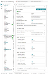
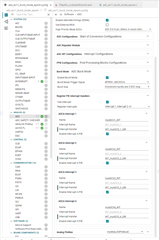
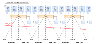
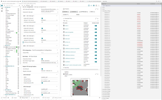
I seperated the round robin wheel into "SOC0 to SOC6" :High Prio (SOC0-SOC5 are used, SOC6 is unused) and "SOC7 to SOC15": Round Robin Low Prio(SOC7-SOC15 are used, 3 times a size 3 burst, rince an repeat).

SOC0 to SOC5 are ALL triggered by the ePWM1 ADCSOCA event, RoundRobin-Bust (burstsize = 3) is also triggered by the same ePWM1 ADCSOCA event.

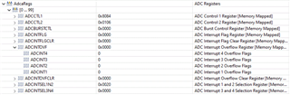
4 ADC IRQs are generated: ADC INT1 at EOC of SOC1 (for test purpose only), ADC INT2 at EOC of SOC3 (for test purpose only), ADC INT3 at EOC of SOC5 (IRQ which im primarily interested in), 

ADC INT4 at EOC of SOC15 (for test purpose only)

To my question:

Im quite puzzled, because I thought the IRQs: ADC INT1, ADC INT2, ADC INT3 are always raised and my ISR is always executed at that moment the SOC EOC events are happening.

Debugging should show me something like. Download+Debug, I press start, ADC INT1 happens, ISR is called, breakpoint is hit, core is stopped and only ADCRESULT0 and ADCRESULT1 has a value other than 0x0000, 

But debugging seems to show, that at that moment I finally enter the ISR for ther first time all values "SOC0 to SOC5" and "SOC7 to SOC9" are already acquired (ADCRESULT0 to ADCRESULT5 and ADCRESULT7 to ADCRESULT9 have values other than 0x0000).

What I want: ePWM1 ADCSOCA event appears an triggers HighPrio-SOCs and RR-Burst --> HighPrio-SOCs come first --> SOC0 to SOC5 are acquired --> SOC5 EOC IRQ is raised (handled by ISR) --> RR-Burst SOCs are acquired (parallel to ISR execution in the background, which to be honest I dont realy care that much). The must important thing is, that Im getting my ISR call right after SOC5 EOC happens.

But for me it looks like, that all SOCs triggered from the same event are first acquired and than my ISRs are called. 

Please can somebody explain to me whats happening?

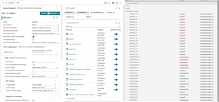
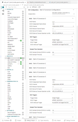
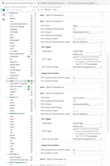
Alternatively, I tried to use Repeater1 (also triggered by the ePWM1 ADCSOCA event) to delay the trigger of the bust block until all HighPrio-SOCs are acquired. In this case the bust block is triggered by Repeater1.

But sadly a get an assert while ADC Bust initialisation ADC_setBurstModeConfig() --> ASSERT(((uint16_t)trigger & ~((uint16_t)0x1FU)) == 0U). Initialisation code is CCS Theia 1.4.1 generated. What's the problem here?

Further question is there a smarter way to get what i want. Using pure round robin acquisition doesn't work. I have to much total SOCs. On the real project I have per ADC core always 4 high prio SOCs and 7 to 9 round robin SOCs.

With best regards, Martin

  • Hi Martin,

    Looks like there is only one ISR function in your code base on the snaphots provided, which is __interrupt void INT_myADC0_1_ISR() which is only mapped to ADCINT1 (INT_ADCA1).  Clearing and acknowledging the other ISRs seems to be happening in that ISR routine.  This is probably the reason why you are not seeing the expected results.

    You would need to create 3 more ISR functions for each of the ISRs INT_ADCA2, INT_ADCA3 and INT_ADCA4, map/register these additional ISR to the interrupt controller using  Interrupt_register() function and enable them using the Interrupt_enable() function.  Lastly, remove the clearing and acknowledging of the other interrupts in INT_myADC0_1_ISR() and transfer these accordingly to the corresponding ISRs.

    Regards,

    Joseph

  • Hi Joseph,

    thank you very much for your reply. In fact INT_myADC0_1_ISR() was mapped to ADCINT1 (INT_ADCA1), ADCINT2 (INT_ADCA2) and ADCINT3 (INT_ADCA3). But one ISR for all three IRQs was sloppy nevertheless, so I implemented your recommendations just to be sure.

    Sadly the behavior is just the same. At that moment I enter INT_myADC0_1_ISR() (which should be entered after SOC1 EOC) for the first time after pressing RUN, all other SOCs: "SOC2 to SOC5" and "SOC7 to SOC9" are already acquired.

    Just to recap, what I expect with my code: ePWM1 ADCSOCA event triggers the HighPrio-SOCs and the RR-Burst --> HighPrio-SOCs should come first --> SOC0 is acquired --> SOC1 is acquired --> SOC1 EOC IRQ is raised --> INT_myADC0_1_ISR() is called --> when I break in INT_myADC0_1_ISR(), I expect register ADCRESULT0 and ADCRESULT1 to have a value other than 0x000 and all other registers ADCRESULTx to have a value of 0x0000. Which they dont have.

    For me, it just looks like that all of the SOCs triggered by ePWM1 ADCSOCA will be acquired first, and than afterwards all of the IRQs raised while acquirering SOCs will be handled, which doesnt seem right.

    I added all of the relevant configuration,I hope that helps. Maybe I forgot to check a box.

    Furthermore, is there any chance to halt the ADC core while pending on a breakpoint. Other controllers have something like: "Stop PWM/Timer while breaking", configurable with the help of a function, a asm-directive or via a register. Maybe Im getting fooled by the debugger. My theory is, the code is just fine, but the ADC core doesnt stop at the breakpoint and continues to acquire all other SOCs and at that moment the IDE is finally notified/updated all the results are written in the ADC result registers.

    I hope you can help me in this matter.

    With best regards,

    Martin

  • Hi Martin,

    Ok, let's inspect some ADC register contents to see what's going on.  In the Register view, can you display AdcaRegs.ADCINTOVF (ADC overflow register) as below:

    Also display some Peripheral Interrupt registers specifically PieCtrlRegs.PIEIER1 and PIEIER10 and expand to show the individual fields as below:

    Setting a breakpoint inside the ADC ISR halts the conversions and prevents the update of the ADC results registers.

    Regards,

    Joseph

  • Hi Joseph,

    "Setting a breakpoint inside the ADC ISR halts the conversions and prevents the update of the ADC results registers."

    Than it seem like, SOCs are all acquired before the first ISR is called.

    Here I got the screen shots you asked me about. Once again, the program was held the fist time after pressing "Run" in ADCA_INT1_ISR INT_myADC0_1_ISR() after (supposedly) the SOC1 EOC event.

    Please notice, I continued steppig through the program from breakpoint to breakpoint but a "1" in any of AdcaRegs.ADCINTOVFs register never came up.

    I hope you maybe see something, which I dont.

    Best regards,

    Martin

  • Hi Martin,

    Thanks for providing the register snapshots.  I'm able to get the information i needed based on the register contents.  Interrupt 1-4 mapping is correct and interrupts seem to be firing based on the flags.  I can also see that SOC0 is mapped to ADC CH1 while SOC1 to SOC5 is mapped to ADC CH0 and TRIGSEL for SOC0-5 is EPWM.  SOC7-9 are triggered with SW (TRIGSEL=0) and channel is mapped to CH0, CH1 and CH2 respectively.  Just wanted to confirm that this was the intent and you have the physical channels connected to signal sources.

    Regards,

    Joseph

  • Hi Joseph,

    Im using the TI LauchPad kit with TMS320F28P650DK9 on it. The software Im using is based on the TI code example "adc_ex11_burst_mode_epwm" hence the name of my project.

    PWM is configured like this:

    PWM configuration remains the same like in "adc_ex11_burst_mode_epwm". ADC part was modified by me, just to test my intended high prio/rr setup as a prove of concept for our coming project. 

    To your question: No there aren't any physical signal sources connected to the channels. It's just the LauchPad as it is. All sampled adc channels are floating. Could this be the problem?

    For my prove of concept, I just wanted to see if my high prio/rr setup works and if the controller behaves in a comprehensible matter. SOC channel mapping for me in this case is insignificant. I just wanted to see, that values are sampled and that the values are sampled and interrupts are raised in me intended order.

    High Prio:"TRIGSEL for SOC0-5 is EPWM":  My intention, TRIGSEL EPWM triggers SOC0-5, ADC samples SOC0 first, than SOC1, than SOC2, .... , than SOC5.

    Round Robin: "TRIGSEL for SOC7-9 is SW (TRIGSEL=0)": My intention, BURSTTRIGSEL is also EPWM and the burst mode trigger overrides the SW TRIGSEL for SOC7-9.

    I hope i could provide all the information that you need.

    With best regards

    Martin