This thread has been locked.

If you have a related question, please click the "Ask a related question" button in the top right corner. The newly created question will be automatically linked to this question.

TMS320F280039C: High-Resolution Pulse Width Modulator :- Issue with using TBPHSHR register for High-Resolution Phase shift

Part Number: TMS320F280039C
Other Parts Discussed in Thread: SYSCONFIG

Tool/software:

Hello team,

Here i want to add my 2 observations with TBPHSHR register for High-Resolution Phase shift.

Microcontroller i'm using :- TMS320F280039C

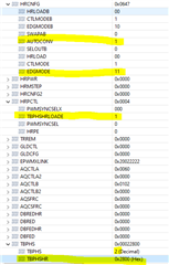
My current configurations in sysconfig are as per below

EPWMCLK:- 120MHZ

Time Base Clock Divider: - Divide clock by 1 

High Speed Clock Divider:- Divide clock by 1 

Time Base Period - 1000

Counter Mode:-  Up - count mode

For my EPWM Peripheral:- EPWM3 Sync-in source is EPWM4 sync-out signal.

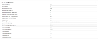
currently we are having Phase shift resolution of 0.36(360 degree/1000).

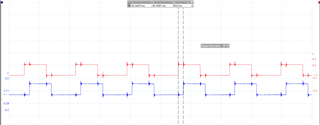
when i am using ePWM functionality of phase shift by Enabling Phase Shift Load by giving Phase Shift value, i am achieving required desired phase shift between EPWM3 and EPWM4. 

1) now i want to use the HRPWM for achieving High-Resolution Phase shift. 

Configurations in sysconfig done as per below 

when i build the project, then in generated files -> board.c -> Board_init function is generated in which EPWM_init function is called in which HRPWM_setPhaseShift function is called.

As expected i should get 0x0064 in TBPHS register and 0x2800 in TBPHSHR register.

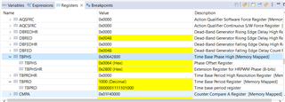
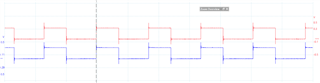
if we see it in degree then that means 36 degree (0X64 IN TBPHS Register) which should give 833 ns Phase shift between EPWM3 and EPWM4 and from TBPHSHR Register (0x2800) i.e. 40 is number of MEP STEP and 1 MEP STEP is 180 ps that means 7.2ns (0.31 Degree). i am expecting here total 36.31 degree. But my observation is quiet stranger. when i am checking PWM Phase Shift between EPWM3 and EPWM4 there is Zero degree Phase shift.

is there anything i am missing in configuration?

2) As i am not able to get desired phase shift with above configurations, so i am not enabling HRPWM from sysconfig and instead i am using HRPWM_setPhaseShift function in code simply.

for example, if i call HRPWM_setPhaseShift function with (0x6428), that means i am expecting 36.31 degree (Phase shift between EPWM3 and EPWM4 should be of 840.2ns). but only 36 degree phase shift shift we are getting remaining 0.31 degree phase shift still we are not getting despite of using HRPWM for High-Resolution Phase shift. here we are expecting 840.2 ns but we are only achieving 833 ns. the finite resolution for remaining fraction part we are not achieving even though after using HRPWM_setPhaseShift function along withHRPWM_enablePhaseShiftLoad. 

also we checked for HRPWM_setHiResPhaseShiftOnly as well, but it didn't worked.

we have taken no. of different tests to verify the same and we found that we are not able to get the finite resolution for remaining fraction part with HRPWM functionality.

Is there any more functions we need to include or anything we are missing let me know.

Thank you.

  • Hi Shirish,

    Sorry for the delay, I will take a look at the query and respond by tomorrow.

    Thanks

  • Hi Shirish,

    For HRPWM phase shift we also need to enable epwm phase shift as well as HRPWM phase shift in sysconfig

    Include the EPWM_enablePhaseShiftLoad() also along with HRPWM and have some non-zero phase shift in and have a non-zero value in phase shift for sync in.

  • Hello Prarthan,

    For HRPWM phase shift we also need to enable epwm phase shift as well as HRPWM phase shift in sysconfig :- as shown in in attached snap shot this is already done and checked, and i've already included EPWM_enablePhaseShiftLoad() also along with HRPWM and have non-zero value in phase shift, but its not working as expected.

  • Hi Shirish,

    Attaching the project I used with F28003x control card. I modified the EX1 project for TBPHSHR
    When you change just the TBPHSHR you will see that the EPWM3 is moving.

    There are two things in sysconfig I had change the MEP edge control mode and TBPHS writing when using the HRPWM is enabled. You can see that I wrote those after Board_Init()

    Second is the phase shift of TBPHSHR is opposite to TBPHS so adjust TBPHS and TBPHSHR accordingly to get the desired value, thread attached here :https://e2e.ti.com/support/microcontrollers/c2000-microcontrollers-group/c2000/f/c2000-microcontrollers-forum/1073047/tms320f280049-hrpwm-tbphs-and-tbphshr-move-waveform-in-opposite-directions

    Third is make sure your oscilloscope is capable for high resolution else you wont see the exact resolution, we recommend 500Mhz scope but atleast 200Mhz can give you required resolution

    hrpwm_ex1_duty_sfo_sdk.zip

    Please let us know if you are not able to see above scope shot behavior.

    Thanks

  • Hello Prarthan,
    Thanks for your reply, We have tried your Example code and have following observations: 

    Observation 1:

    Is my understanding correct that if the Epwm1(Master) and Epwm3 (Slave) and is in Leading Phase shift with following configurations:

    •      PWM mode: Up count Mode.
    •      Epwm3 (Slave) PHSDIR was set to 1 to get a leading shift.
    •      EPWM clock = 100Mhz
    •      TBPHS is 2 (i.e. 2 * 10ns = 20ns)
    •      TBPHSHR is 40 (i.e. 40 * ~150ps = ~6ns)

     The phase shift should be 20ns - 6ns = 14ns and we have got 1.7ns. Can you please Clarify if this is the correct understanding?

    OR

    Is it the case that 1 coarse is divided by 255. So, in the above Example, 10ns/255 = 0.03921ns.
    and with this step the TBPHSHR is applying the Phase shift.


    Observation 2:

    PWM mode: Up count Mode.

    TBPRD: 1000

    Ttbclk = 8.33ns


    TBPHSR


    0

    10

    20

    30

    40

    50

    100

    150

    200

    250

    TBPHS

    1

    9.44ns

    9.52ns

    9.8ns

    10.48ns

    10.80ns

    10.96ns

    12.48ns

    14.12ns

    15.6ns

    17.12ns


    2

    970ps

    1.16ns

    1.52ns

    1.80ns

    2.08ns

    2.76ns

    4.16ns

    5.56ns

    7.04ns

    8.76ns


    3

    7.3ns

    7.6ns

    6.7ns

    6.480ns

    6.280ns

    5.64ns

    3.84ns

    3.48ns

    1.2ns

    1.12ns


    4

    15.9ns

    15.8ns

    15.32ns

    14.60ns

    14.08ns

    13.96ns

    12.92ns

    10.6ns

    9.88ns

    8ns


    With every 10 steps we should get the Phase shift of 150ps*10steps = 1.5ns (as for 39C Controller 150ps is the Typical step size), but it is observed that we are getting Phase shift of ~320ps with every 10-step increase.


    Also, In HRPWM although there are maximum 255 MEP steps, Is it case that maximum valid no. of MEP steps = 1 coarse step time / 150ps? If yes, then what if we give TBPHSHR value beyond that? 

    for example,
    MEP step size = 150ps
    1 coarse time = 15ns
    No. of MEP steps(within 15ns) = 100.

    what if the TBPHSHR value is above 100, Is it valid?

  • Hi Tejas,

    Since we are using AUTOCONVERSION, MEP_ScaleFactor (Number of MEP steps per coarse step) is in the HRMSTEP register. HRMSTEP value is calculated by SFO.

    But the TBPHSHR value scales from 0-0xFF(255), such that when you enter 0xFF in TBPHSHR you would scale it to one full coarse period ~8.33ns for 120Mhz EPWMCLK
    Hence for other values it scales the input TBPHSHR value considering that 255 steps is equivalent to the HRMSTEP value

    Thanks.